|
|

Table Of Contents
Standard and Extended Access Lists
Restrictions on Using IP Router Commands with MLS Enabled
Introduction to IP Multicast MLS
IP Multicast MLS Network Topology
Layer 2 Multicast Forwarding Table
Layer 3-Switched Multicast Packet Rewrite
Partially and Completely Switched Flows
Layer 3-Switched Packet Rewrite
Guidelines for External Routers
Multilayer Switching Overview
This chapter provides an overview of Multilayer Switching (MLS).
Note
The information in this chapter is a brief summary of the information contained in the Catalyst 5000 Series Multilayer Switching User Guide. The commands and configurations described in this guide apply only to the devices that provide routing services. Commands and configurations for Catalyst 5000 series switches are documented in the Catalyst 5000 Series Multilayer Switching User Guide.
MLS provides high-performance Layer 3 switching for Cisco routers and switches. MLS switches IP data packets between subnets using advanced application-specific integrated circuit (ASIC) switching hardware. Standard routing protocols, such as Open Shortest Path First (OSPF), Enhanced Interior Gateway Routing Protocol (Enhanced IGRP), Routing Information Protocol (RIP), and Intermediate System-to-Intermediate System (IS-IS), are used for route determination.
MLS enables hardware-based Layer 3 switching to offload routers from forwarding unicast IP data packets over shared media networking technologies such as Ethernet. The packet forwarding function is moved onto Layer 3 Cisco series switches whenever a partial or complete switched path exists between two hosts. Packets that do not have a partial or complete switched path to reach their destinations still use routers for forwarding packets.
MLS also provides traffic statistics as part of its switching function. These statistics are used for identifying traffic characteristics for administration, planning, and troubleshooting. MLS uses NetFlow Data Export (NDE) to export the flow statistics.
Procedures for configuring MLS and NDE on routers are provided in the "Configuring IP Multilayer Switching" chapter.
Procedures for configuring MLS and NDE on routers are provided in the following chapters in this publication:
•
•
•
This chapter describes MLS. It contains the following sections:
•
•
•
Terminology
The following terminology is used in the MLS chapters:
•
•
•
Introduction to MLS
Layer 3 protocols, such as IP and Internetwork Packet Exchange (IPX), are connectionless—they deliver each packet independently of each other. However, actual network traffic consists of many end-to-end conversations, or flows, between users or applications.
A flow is a unidirectional sequence of packets between a particular source and destination that share the same protocol and transport-layer information. Communication from a client to a server and from the server to the client is in separate flows. For example, HTTP Web packets from a particular source to a particular destination are in a separate flow from File Transfer Protocol (FTP) file transfer packets between the same pair of hosts.
Flows can be based on only Layer 3 addresses. This feature allows IP traffic from multiple users or applications to a particular destination to be carried on a single flow if only the destination IP address is used to identify a flow.
The NFFC maintains a Layer 3 switching table (MLS cache) for the Layer 3-switched flows. The cache also includes entries for traffic statistics that are updated in tandem with the switching of packets. After the MLS cache is created, packets identified as belonging to an existing flow can be Layer 3-switched based on the cached information. The MLS cache maintains flow information for all active flows. When the Layer 3-switching entry for a flow ages out, the flow statistics can be exported to a flow collector application.
For information on multicast MLS, see the "Introduction to IP Multicast MLS" section in this chapter.
Key MLS Features
Table 37 lists the key MLS features.
Table 37 Summary of Key Features
Ease of Use
Is autoconfigurable and autonomously sets up its Layer 3 flow cache. Its "plug-and-play" design eliminates the need for you to learn new IP switching technologies.
Transparency
Requires no end-system changes and no renumbering of subnets. It works with DHCP1 and requires no new routing protocols.
Standards Based
Uses IETF2 standard routing protocols such as OSPF and RIP for route determination. You can deploy MLS in a multivendor network.
Investment Protection
Provides a simple feature-card upgrade on the Catalyst 5000 series switches. You can use MLS with your existing chassis and modules. MLS also allows you to use either an integrated RSM or an external router for route processing and Cisco IOS services.
Fast Convergence
Allows you to respond to route failures and routing topology changes by performing hardware-assisted invalidation of flow entries.
Resilience
Provides the benefits of HSRP3 without additional configuration. This feature enables the switches to transparently switch over to the Hot Standby backup router when the primary router goes offline, eliminating a single point of failure in the network.
Access Lists
Allows you to set up access lists to filter, or to prevent traffic between members of different subnets. MLS enforces multiple security levels on every packet of the flow at wire speed. It allows you to configure and enforce access control rules on the RSM. Because MLS parses the packet up to the transport layer, it enables access lists to be validated. By providing multiple security levels, MLS enables you to set up rules and control traffic based on IP addresses and transport-layer application port numbers.
Accounting and
Traffic ManagementAllows you to see data flows as they are switched for troubleshooting, traffic management, and accounting purposes. MLS uses NDE to export the flow statistics. Data collection of flow statistics is maintained in hardware with no impact on switching performance. The records for expired and purged flows are grouped and exported to applications such as NetSys for network planning, RMON24 traffic management and monitoring, and accounting applications.
Network Design Simplification
Enables you to speed up your network while retaining the existing subnet structure. It makes the number of Layer 3 hops irrelevant in campus design, enabling you to cope with increases in any-to-any traffic.
Media Speed Access to Server Farms
You do not need to centralize servers in multiple VLANs to get direct connections. By providing security on a per-flow basis, you can control access to the servers and filter traffic based on subnet numbers and transport-layer application ports without compromising Layer 3 switching performance.
Faster Interworkgroup Connectivity
Addresses the need for higher-performance interworkgroup connectivity by intranet and multimedia applications. By deploying MLS, you gain the benefits of both switching and routing on the same platform.
1 DHCP = Dynamic Host Configuration Protocol
2 IETF = Internet Engineering Task Force
3 HSRP = Hot Standby Router Protocol
4 RMON2 = Remote Monitoring 2
MLS Implementation
This section provides a step-by-step description of MLS implementation.
Note
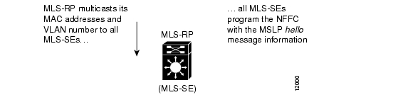
The MLSP informs the Catalyst 5000 series switch of the MLS-RP MAC addresses used on different VLANs and the MLS-RP's routing and access list changes. Through this protocol, the MLS-RP multicasts its MAC and VLAN information to all MLS-SEs. When the MLS-SE hears the MLSP hello message indicating an MLS initialization, the MLS-SE is programmed with the MLS-RP MAC address and its associated VLAN number (see Figure 63).
Figure 63 MLS Implementation
In Figure 64, Host A and Host B are located on different VLANs. Host A initiates a data transfer to Host B. When Host A sends the first packet to the MLS-RP, the MLS-SE recognizes this packet as a candidate packet for Layer 3 switching because the MLS-SE has learned the MLS-RP's destination MAC address and VLAN through MLSP. The MLS-SE learns the Layer 3 flow information (such as the destination address, source address, and protocol port numbers), and forwards the first packet to the MLS-RP. A partial MLS entry for this Layer 3 flow is created in the MLS cache.
The MLS-RP receives the packet, looks at its route table to determine how to forward the packet, and applies services such as Access Control Lists (ACLs) and class of service (COS) policy.
The MLS-RP rewrites the MAC header adding a new destination MAC address (Host B's) and its own MAC address as the source.
Figure 64 MLS Implementation
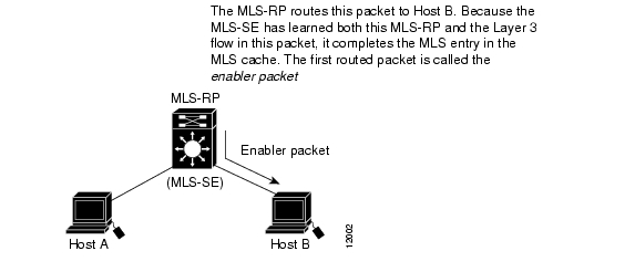
The MLS-RP routes the packet to Host B. When the packet appears back on the Catalyst 5000 series switch backplane, the MLS-SE recognizes the source MAC address as that of the MLS-RP, and that the packet's flow information matches the flow for which it set up a candidate entry. The MLS-SE considers this packet an enabler packet and completes the MLS entry (established by the candidate packet) in the MLS cache (see Figure 65).
Figure 65 MLS Implementation
After the MLS entry has been completed, all Layer 3 packets with the same flow from Host A to Host B are Layer 3 switched directly inside the switch from Host A to Host B, bypassing the router (see Figure 66). After the Layer 3-switched path is established, the packet from Host A is rewritten by the MLS-SE before it is forwarded to Host B. The rewritten information includes the MAC addresses, encapsulations (when applicable), and some Layer 3 information.
The resultant packet format and protocol behavior is identical to that of a packet that is routed by the RSM or external Cisco router.
Note
Figure 66 MLS Implementation
See the Catalyst 5000 Series Multilayer Switching User Guide for additional network implementation examples that include network topologies that do not support MLS.
Standard and Extended Access Lists
Note
MLS allows you to enforce access lists on every packet of the flow without compromising MLS performance. When you enable MLS, standard and extended access lists are handled at wire speed by the MLS-SE. Access lists configured on the MLS-RP take effect automatically on the MLS-SE.
Additionally, route topology changes and the addition of access lists are reflected in the switching path of MLS.
Consider the case where an access list is configured on the MLS-RP to deny access from Station A to Station B. When Station A wants to communicate with Station B, it sends the first packet to the MLS-RP. The MLS-RP receives this packet and checks to learn if this packet flow is permitted. If an ACL is configured for this flow, the packet is discarded. Because the first packet for this flow does not return from the MLS-RP, an MLS cache entry is not established by the MLS-SE.
In another case, access lists are introduced on the MLS-RP while the flow is already being Layer 3 switched within the MLS-SE. The MLS-SE immediately enforces security for the affected flow by purging it.
Similarly, when the MLS-RP detects a routing topology change, the appropriate MLS cache entries are deleted in the MLS-SE. The techniques for handling route and access list changes apply to both the RSM and directly attached external routers.
Restrictions on Using IP Router Commands with MLS Enabled
The following Cisco IOS commands affect MLS on your router:
•
•
•
•
•
General Guidelines
The following is a list of general guidelines to enabling MLS:
•
•
Introduction to IP Multicast MLS
The IP multicast MLS feature provides high-performance, hardware-based, Layer 3 switching of IP multicast traffic for routers connected to LAN switches.
An IP multicast flow is a unidirectional sequence of packets between a multicast source and the members of a destination multicast group. Flows are based on the IP address of the source device and the destination IP multicast group address.
IP multicast MLS switches IP multicast data packet flows between IP subnets using advanced, ASIC switching hardware, thereby off loading processor-intensive, multicast packet routing from network routers.
The packet forwarding function is moved onto the connected Layer 3 switch whenever a supported path exists between a source and members of a multicast group. Packets that do not have a supported path to reach their destinations are still forwarded in software by routers. Protocol Independent Multicast (PIM) is used for route determination.
IP Multicast MLS Network Topology
IP multicast MLS requires specific network topologies to function correctly. In each of these topologies, the source traffic is received on the switch, traverses a trunk link to the router, and returns to the switch over the same trunk link to reach the destination group members. The basic topology consists of a switch and an internal or external router connected through an ISL or 802.1Q trunk link.
Figure 67 shows this basic configuration before and after IP multicast MLS is deployed (assuming a completely switched flow). The topology consists of a switch, a directly connected external router, and multiple IP subnetworks (VLANs).
The network in the upper diagram in Figure 67 does not have the IP multicast MLS feature enabled. Note the arrows from the router to each multicast group in each VLAN. In this case, the router must replicate the multicast data packets to the multiple VLANs. The router can be easily overwhelmed with forwarding and replicated multicast traffic if the input rate or the number of outgoing interfaces increases.
As shown in the lower diagram in Figure 67, this potential problem is prevented by having the switch hardware forward the multicast data traffic. (Multicast control packets are still moving between the router and switch.)
Figure 67 Basic IP Multicast MLS Network Topology
Benefits of multicast MLS are as follows:
•
•
•
•
IP Multicast MLS Components
An IP multicast MLS network topology has two components:
•
•
Layer 2 Multicast Forwarding Table
The MMLS-SE uses the Layer 2 multicast forwarding table to determine on which ports Layer 2 multicast traffic should be forwarded (if any). The Layer 2 multicast forwarding table is populated by enabling CGMP, IGMP snooping, or GMRP on the switch. These entries map the destination multicast MAC address to outgoing switch ports for a given VLAN.
Layer 3 Multicast MLS Cache
The MMLS-SE maintains the Layer 3 MLS cache to identify individual IP multicast flows. Each entry is of the form {source IP, destination group IP, source VLAN}. The maximum MLS cache size is 128K and is shared by all MLS processes on the switch (such as IP unicast MLS and IPX MLS). However, if the total of cache entries exceeds 32K, there is increased probability that a flow will not be switched by the MMLS-SE and will get forwarded to the router.
The MMLS-SE populates the MLS cache using information learned from the routers participating in IP multicast MLS. The router and switch exchange information using the multicast MLSP.
Whenever the router receives traffic for a new flow, it updates its multicast routing table and forwards the new information to the MMLS-SE using multicast MLSP. In addition, if an entry in the multicast routing table is aged out, the router deletes the entry and forwards the updated information to the MMLS-SE.
The MLS cache contains flow information for all active multilayer switched flows. After the MLS cache is populated, multicast packets identified as belonging to an existing flow can be Layer 3 switched based on the cache entry for that flow. For each cache entry, the MMLS-SE maintains a list of outgoing interfaces for the destination IP multicast group. The MMLS-SE uses this list to determine on which VLANs traffic to a given multicast flow should be replicated.
IP Multicast MLS Flow Mask
IP multicast MLS supports a single flow mask, source destination vlan. The MMLS-SE maintains one multicast MLS cache entry for each {source IP, destination group IP, source VLAN}. The multicast source destination vlan flow mask differs from the IP unicast MLS source destination ip flow mask in that, for IP multicast MLS, the source VLAN is included as part of the entry. The source VLAN is the multicast Reverse Path Forwarding (RPF) interface for the multicast flow.
Layer 3-Switched Multicast Packet Rewrite
When a multicast packet is Layer 3-switched from a multicast source to a destination multicast group, the MMLS-SE performs a packet rewrite based on information learned from the MMLS-RP and stored in the multicast MLS cache.
For example, if Server A sends a multicast packet addressed to IP multicast group G1 and members of group G1 are on VLANs other than the source VLAN, the MMLS-SE must perform a packet rewrite when it replicates the traffic to the other VLANs (the switch also bridges the packet in the source VLAN).
When the MMLS-SE receives the multicast packet, it is formatted similarly to the sample shown in Table 38.
The MMLS-SE rewrites the packet as follows:
•
•
The result is a rewritten IP multicast packet that appears to have been routed by the router. The MMLS-SE replicates the rewritten packet onto the appropriate destination VLANs, where it is forwarded to members of IP multicast group G1.
After the MMLS-SE performs the packet rewrite, the packet is formatted as shown in Table 39:
Partially and Completely Switched Flows
When at least one outgoing router interface for a given flow is multilayer switched, and at least one outgoing interface is not multilayer switched, that flow is considered partially switched. When a partially switched flow is created, all multicast traffic belonging to that flow still reaches the router and is software forwarded on those outgoing interfaces that are not multilayer switched.
A flow might be partially switched instead of completely switched in the following situations:
•
•
•
•
•
•
•
•
•
When all the outgoing router interfaces for a given flow are multilayer switched, and none of the situations described applies to the flow, that flow is considered completely switched. When a completely switched flow is created, the MMLS-SE prevents multicast traffic bridged on the source VLAN for that flow from reaching the MMLS-RP interface in that VLAN, reducing the load on the router.
One consequence of a completely switched flow is that the router cannot record multicast statistics for that flow. Therefore, the MMLS-SE periodically sends multicast packet and byte count statistics for all completely switched flows to the router using multicast MLSP. The router updates the corresponding multicast routing table entry and resets the expiration timer for that multicast route.
Introduction to IPX MLS
The IPX MLS feature provides high-performance, hardware-based, Layer 3 switching for LAN switches. IPX data packet flows are switched between networks, off loading processor-intensive packet routing from network routers.
Whenever a partial or complete switched path exists between two hosts, packet forwarding occurs on Layer 3 switches. Packets without such a partial or complete switched path are still forwarded by routers to their destinations. Standard routing protocols such as RIP, Enhanced IGRP, and NetWare Link Services Protocol (NLSP) are used for route determination.
IPX MLS also allows you to debug and trace flows in your network. Use MLS explorer packets to identify which switch is handling a particular flow. These packets aid you in path detection and troubleshooting.
IPX MLS Components
An IPX MLS network topology has the following components:
•
•
•
IPX MLS Flows
Layer 3 protocols such as IP and IPX are connectionless—they deliver every packet independently of every other packet. However, actual network traffic consists of many end-to-end conversations, or flows, between users or applications.
A flow is a unidirectional packet sequence between a particular source and destination that share identical protocol and network-layer information. Communication flows from a client to a server and from the server to the client are distinct.
Flows are based only on Layer 3 addresses. If a destination IPX address identifies a flow, then IPX traffic from multiple users or applications to a particular destination can be carried on a single flow.
Layer 3-switched flows appear in the MLS cache, a special Layer 3 switching table is maintained by the NFFC II. The cache contains traffic statistics entries that are updated in tandem with packet switching. After the MLS cache is created, packets identified as belonging to an existing flow can be Layer 3 switched. The MLS cache maintains flow information for all active flows.
MLS Cache
The MLS-SE maintains a cache for IPX MLS flows and maintains statistics for each flow. An IPX MLS cache entry is created for the initial packet of each flow. Upon receipt of a packet that does not match any flow in the MLS cache, a new IPX MLS entry is created.
The state and identity of the flow are maintained while packet traffic is active; when traffic for a flow ceases, the entry ages out. You can configure the aging time for IPX MLS entries kept in the MLS cache. If an entry is not used for the specified period of time, the entry ages out and statistics for that flow can be exported to a flow collector application.
The maximum MLS cache size is 128,000 entries. However, an MLS cache larger than 32,000 entries increases the probability that a flow will not be switched by the MLS-SE and will get forwarded to the router.
Note
Flow Mask Modes
Two flow mask modes—destination mode and destination-source mode—determine how IPX MLS entries are created for the MLS-SE.
You determine the mode when you configure IPX access lists on the MLS-RP router interfaces. Each MLS-RP sends MLSP messages about its flow mask to the MLS-SE, which performs Layer 3 switching. The MLS-SE supports only the most specific flow mask for its MLS-RPs. If it detects more than one mask, it changes to the most specific mask and purges the entire MLS cache. When an MLS-SE exports cached entries, it creates flow records from the most current flow mask mode. Depending on the current mode, some fields in the flow record might not have values. Unsupported fields are filled with a zero (0).
The two modes are described, as follows:
•
•
Note
Layer 3-Switched Packet Rewrite
When a packet is Layer 3 switched from a source host to a destination host, the switch (MLS-SE) performs a packet rewrite based on information it learned from the router (MLS-RP) and then stored in the MLS cache.
If Host A and Host B are on different VLANs and Host A sends a packet to the MLS-RP to be routed to Host B, the MLS-SE recognizes that the packet was sent to the MAC address of the MLS-RP. The MLS-SE then checks the MLS cache and finds the entry matching the flow in question.
When the MLS-SE receives the packet, it is formatted as shown in Table 40:
Table 40 Layer 3-Switched Packet Header Sent to the MLS-RP
Destination
Source
Length
Checksum/ IPX Length/ Transport Control1
Packet Type
Destination Net/Node/ Socket
Source Net/Node/ Socket
Data
PAD/FCS
MLS-RP MAC
Host A MAC
Host B IPX
Host A IPX
1 Transport Control counts the number of times this packet has been routed. If this number is greater than the maximum (the default is 16), then the packet is dropped.
The MLS-SE rewrites the Layer 2 frame header, changing the destination MAC address to that of Host B and the source MAC address to that of the MLS-RP (these MAC addresses are stored in the IPX MLS cache entry for this flow). The Layer 3 IPX addresses remain the same. The MLS-SE rewrites the switched Layer 3 packets so that they appear to have been routed by a router.
The MLS-SE forwards the rewritten packet to Host B's VLAN (the destination VLAN is saved in the IPX MLS cache entry) and Host B receives the packet.
After the MLS-SE performs the packet rewrite, the packet is formatted as shown in Table 41:
IPX MLS Operation
Figure 68 shows a simple IPX MLS network topology:
•
•
•
When Host A initiates a file transfer to Host B, an IPX MLS entry for this flow is created (see the first item in Figure 68's table). When the MLS-RP forwards the first packet from Host A through the switch to Host B, the MLS-SE stores the MAC addresses of the MLS-RP and Host B in the IPX MLS entry. The MLS-SE uses this information to rewrite subsequent packets from Host A to Host B.
Similarly, a separate IPX MLS entry is created in the MLS cache for the traffic from Host A to Host C, and for the traffic from Host C to Host A. The destination VLAN is stored as part of each IPX MLS entry so that the correct VLAN identifier is used for encapsulating traffic on trunk links.
Figure 68 IPX MLS Example Topology
Standard Access Lists
Note
IPX MLS enforces access lists on every packet of the flow, without compromising IPX MLS performance. The MLS-SE handles permit traffic supported by MLS at wire speed.
Note
The MLS switching path automatically reflects route topology changes and the addition or modification of access lists on the MLS-SE. The techniques for handling route and access list changes apply to both the RSM and directly attached external routers.
For example, for Stations A and B to communicate, Station A sends the first packet to the MLS-RP. If the MLS-RP is configured with an access list to deny access from Station A to Station B, the MLS-RP receives the packet, checks its access list permissions to learn if the packet flow is permitted, and then discards the packet. Because the MLS-SE does not receive the returned first packet for this flow from the MLS-RP, the MLS-SE does not create an MLS cache entry.
In contrast, if the MLS-SE is already Layer 3 switching a flow and the access list is created on the MLS-RP, MLSP notifies the MLS-SE, and the MLS-SE immediately purges the affected flow from the MLS cache. New flows are created based on the restrictions imposed by the access list.
Similarly, when the MLS-RP detects a routing topology change, the MLS-SE deletes the appropriate MLS cache entries, and new flows are created based on the new topology.
Guidelines for External Routers
When using an external router, follow these guidelines:
•
•
•
Features That Affect MLS
This section describes how certain features affect MLS.
Access Lists
The following sections describe how access lists affect MLS.
Input Access Lists
Router interfaces with input access lists cannot participate in MLS. If you configure an input access list on an interface, all packets for a flow that are destined for that interface go through the router (even if the flow is allowed by the router it is not Layer 3 switched). Existing flows for that interface get purged and no new flows are cached.
Note
Output Access Lists
If an output access list is applied to an interface, the MLS cache entries for that interface are purged. Entries associated with other interfaces are not affected; they follow their normal aging or purging procedures.
Applying an output access list to an interface, when the access list is configured using the log, precedence, tos, or establish keywords, prevents the interface from participating in MLS.
Access List Impact on Flow Masks
Access lists impact the flow mask advertised by an MLS-RP. When no access list on any MLS-RP interface, the flow mask mode is destination-ip (the least specific). When there is a standard access list is on any of the MLS-RP interfaces, the mode is source-destination-ip. When there is an extended access list is on any of the MLS-RP interfaces, the mode is ip-flow (the most specific).
Reflexive Access Lists
Router interfaces with reflexive access lists cannot participate in Layer 3 switching.
IP Accounting
Enabling IP accounting on an MLS-enabled interface disables the IP accounting functions on that interface.
Note
Data Encryption
MLS is disabled on an interface when the data encryption feature is configured on the interface.
Policy Route Maps
MLS is disabled on an interface when a policy route map is configured on the interface.
TCP Intercept
With MLS interfaces enabled, the TCP intercept feature (enabled in global configuration mode) might not work properly. When you enable the TCP intercept feature, the following message is displayed:
Command accepted, interfaces with mls might cause inconsistent behavior.Network Address Translation
MLS is disabled on an interface when Network Address Translation (NAT) is configured on the interface.
Committed Access Rate
MLS is disabled on an interface when committed access rate (CAR) is configured on the interface.
Maximum Transmission Unit
The maximum transmission unit (MTU) for an MLS interface must be the default Ethernet MTU, 1500 bytes.
To change the MTU on an MLS-enabled interface, you must first disable MLS on the interface (enter no mls rp ip global configuration command in the interface). If you attempt to change the MTU with MLS enabled, the following message is displayed:
Need to turn off the mls router for this interface first.If you attempt to enable MLS on an interface that has an MTU value other than the default value, the following message is displayed:
mls only supports interfaces with default mtu size
![]()
![]()
![]()
![]()
![]()
![]()
![]()
![]()
Posted: Tue Jul 25 04:54:25 PDT 2006
All contents are Copyright © 1992--2006 Cisco Systems, Inc. All rights reserved.
Important Notices and Privacy Statement.