|
|

Table Of Contents
Configuring IPX Multilayer Switching
General Configuration Guidelines
Restrictions on Interaction of IPX MLS with Other Features
Restriction on Maximum Transmission Unit Size
IPX MLS Configuration Task List
Adding an IPX MLS Interface to a VTP Domain
Enabling Multilayer Switching Protocol (MLSP) on the Router
Assigning a VLAN ID to a Router Interface
Enabling IPX MLS on a Router Interface
Specifying a Router Interface As a Management Interface
Verifying IPX MLS on the Router
Monitoring and Maintaining IPX MLS on the Router
IPX MLS Configuration Examples
Configuring IPX Multilayer Switching
This chapter describes how to configure your network to perform IPX Multilayer Switching (MLS). This chapter contains these sections:
•
IPX MLS Configuration Task List
•
•
For a complete description of the commands in this chapter, refer to the the Cisco IOS Switching Services Command Reference. To locate documentation of other commands that appear in this chapter, use the command reference master index or search online.
To identify the hardware platform or software image information associated with a feature, use the Feature Navigator on Cisco.com to search for information about the feature or refer to the software release notes for a specific release. For more information, see the section "Identifying Supported Platforms" in the chapter "Using Cisco IOS Software."
Note
Prerequisites
The following prerequisites must be met before IPX MLS can function:
•
•
IPX MLS must be enabled on the router. The minimal configuration steps are described in the section "IPX MLS Configuration Tasks." For more details on configuring IPX routing, refer to the Cisco IOS AppleTalk and Novell IPX Configuration Guide.
Restrictions
This section describes restrictions that apply to configuring IPX MLS on the router.
General Configuration Guidelines
Be aware of the following restrictions:
•
•
•
External Router Guidelines
When using an external router, use the following guidelines:
•
•
•
Access List Restrictions
The following restrictions apply when you use access lists on interfaces that participate in IPX MLS:
•
Note
•
Applying access lists that filter according to packet type, source node, source socket, or destination socket prevents the interface from participating in IPX MLS.
Applying access lists that use the log option prevents the interface from participating in IPX MLS.
•
Restrictions on Interaction of IPX MLS with Other Features
IPX MLS affects other Cisco IOS software features as follows:
•
•
Restriction on Maximum Transmission Unit Size
In IPX the two endpoints of communication negotiate the maximum transmission unit (MTU) to be used. MTU size is limited by media type.
IPX MLS Configuration Task List
To configure one or more routers for IPX MLS, perform the tasks described in the following sections. The number of tasks you perform depends on your particular configuration.
•
•
•
•
•
For examples of IPX MLS configurations, see the "IPX MLS Configuration Examples" section later in this document.
Adding an IPX MLS Interface to a VTP Domain
Caution
Determine which router interfaces you will use as IPX MLS interfaces and add them to the same VTP domain as the switches.
To view the VTP configuration and its domain name on the switch, enter the show mls rp vtp-domain EXEC command at the switch Console> prompt.
To assign an MLS interface to a specific VTP domain on the MLS-RP, use the following command in interface configuration mode:
Router(config-if)# mls rp vtp-domain domain-name
Adds an IPX MLS interface to a VTP domain.
Enabling Multilayer Switching Protocol (MLSP) on the Router
To enable MLSP on the router, use the following command in global configuration mode:
Router(config)# mls rp ipx
Globally enables MLSP on the router. MLSP is the protocol that runs between the MLS-SE and MLS-RP.
Assigning a VLAN ID to a Router Interface
Note
To assign a VLAN ID to an IPX MLS interface, use the following command in interface configuration mode:
Enabling IPX MLS on a Router Interface
To enable IPX MLS on a router interface, use the following command in interface configuration mode:
Specifying a Router Interface As a Management Interface
To specify an interface as the management interface, use the following command in interface configuration mode:
Verifying IPX MLS on the Router
To verify that you have correctly installed IPX MLS on the router, perform the following steps:
Step 1
Step 2
Step 3
Troubleshooting Tips
If you entered either the mls rp ipx interface command or the mls rp management-interface interface command on the interface before assigning it to a VTP domain, the interface will be in the null domain, instead of the VTP domain.
To remove the interface from the null domain and add it to a new VTP domain, use the following commands in interface configuration mode:
Monitoring and Maintaining IPX MLS on the Router
To monitor and maintain IPX MLS on the router, use the following command in EXEC mode, as needed:
IPX MLS Configuration Examples
ThisThis example consists of the following sections:
•
•
•
•
•
IPX MLS Network Topology Example
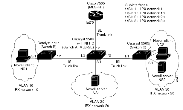
Figure 71 shows an IPX MLS network topology consisting of three Catalyst 5000 series switches and a Cisco 7505 router—all interconnected with ISL trunk links.
Figure 71 Example Network: IPX MLS with Cisco 7505 over ISL
The network is configured as follows:
•
–
–
–
–
•
•
–
–
–
–
•
•
Operation Before IPX MLS Example
Before IPX MLS is implemented, when the source host NC1 (on VLAN 10) sends traffic destined for destination server NS2 (on VLAN 30), Switch B forwards the traffic (based on the Layer 2 forwarding table) to Switch A over the ISL trunk link. Switch A forwards the packet to the router over the ISL trunk link.
The router receives the packet on the VLAN 10 subinterface, checks the destination IPX address, and routes the packet to the VLAN 30 subinterface. Switch A receives the routed packet and forwards it to Switch C. Switch C receives the packet and forwards it to destination server NS2. This process is repeated for each packet in the flow between source host NC1 and destination server NS2.
Operation After IPX MLS Example
After IPX MLS is implemented, when the source host NC1 (on VLAN 10) sends traffic destined for destination server NS2 (on VLAN 30), Switch B forwards the traffic (based on the Layer 2 forwarding table) to Switch A (the MLS-SE) over the ISL trunk link. When the first packet enters Switch A, a candidate flow entry is established in the MLS cache. Switch A forwards the packet to the MLS-RP over the ISL trunk link.
The MLS-RP receives the packet on the VLAN 10 subinterface, checks the destination IPX address, and routes the packet to the VLAN 30 subinterface. Switch A receives the routed packet (the enabler packet) and completes the flow entry in the MLS cache for the destination IPX address of NS2. Switch A forwards the packet to Switch C, where it is forwarded to destination server NS2.
Subsequent packets destined for the IPX address of NS2 are multilayer switched by the MLS-SE based on the flow entry in the MLS cache. For example, subsequent packets in the flow from source host NC1 are forwarded by Switch B to Switch A (the MLS-SE). The MLS-SE determines that the packets are part of the established flow, rewrites the packet headers, and switches the packets directly to Switch C, bypassing the router.
Switch A Configuration
This example shows how to configure Switch A (MLS-SE):
SwitchA> (enable) set vtp domain Corporate mode serverVTP domain Corporate modifiedSwitchA> (enable) set vlan 10Vlan 10 configuration successfulSwitchA> (enable) set vlan 20Vlan 20 configuration successfulSwitchA> (enable) set vlan 30Vlan 30 configuration successfulSwitchA> (enable) set port name 1/1 Router LinkPort 1/1 name set.SwitchA> (enable) set trunk 1/1 on islPort(s) 1/1 trunk mode set to on.Port(s) 1/1 trunk type set to isl.SwitchA> (enable) set port name 1/2 SwitchB LinkPort 1/2 name set.SwitchA> (enable) set trunk 1/2 desirable islPort(s) 1/2 trunk mode set to desirable.Port(s) 1/2 trunk type set to isl.SwitchA> (enable) set port name 1/3 SwitchC LinkPort 1/3 name set.SwitchA> (enable) set trunk 1/3 desirable islPort(s) 1/3 trunk mode set to desirable.Port(s) 1/3 trunk type set to isl.SwitchA> (enable) set mls enable ipxIPX Multilayer switching is enabled.SwitchA> (enable) set mls include ipx 10.1.1.1IPX Multilayer switching enabled for router 10.1.1.1.SwitchA> (enable) set port name 3/1 Destination D2Port 3/1 name set.SwitchA> (enable) set vlan 20 3/1VLAN 20 modified.VLAN 1 modified.VLAN Mod/Ports---- -----------------------20 3/1SwitchA> (enable)Switch B Configuration
This example shows how to configure Switch B:
SwitchB> (enable) set port name 1/1 SwitchA LinkPort 1/1 name set.SwitchB> (enable) set port name 3/1 Source S1Port 3/1 name set.SwitchB> (enable) set vlan 10 3/1VLAN 10 modified.VLAN 1 modified.VLAN Mod/Ports---- -----------------------10 3/1SwitchB> (enable)Switch C Configuration
This example shows how to configure Switch C:
SwitchC> (enable) set port name 1/1 SwitchA LinkPort 1/1 name set.SwitchC> (enable) set port name 3/1 Destination D1Port 3/1 name set.SwitchC> (enable) set vlan 30 3/1VLAN 30 modified.VLAN 1 modified.VLAN Mod/Ports---- -----------------------30 3/1SwitchC> (enable) set port name 4/1 Source S2Port 4/1 name set.SwitchC> (enable) set vlan 30 4/1VLAN 30 modified.VLAN 1 modified.VLAN Mod/Ports---- -----------------------30 3/14/1SwitchC> (enable)MLS-RP Configuration
This example shows how to configure the MLS-RP:
mls rp ipxinterface fastethernet 2/0full-duplexmls rp vtp-domain Engineeringinterface fastethernet2/0.1encapsulation isl 1ipx address 10.1.1.1 255.255.255.0mls rp ipxmls rp management-interfaceinterface fastethernet2/0.10encapsulation isl 10ipx network 10mls rp ipxinterface fastethernet2/0.20encapsulation isl 20ipx network 20mls rp ipxinterface fastethernet2/0.30encapsulation isl 30ipx network 30mls rp ipxThis example shows how to configure the RSM VLAN interfaces with no access lists. Therefore, the flow mask mode is destination.
Building configuration...Current configuration:!version 12.0...ipx routing 0010.0738.2917mls rp ipmls rp ipx...interface Vlan21ip address 10.5.5.155 255.255.255.0ipx network 2121mls rp vtp-domain Engineeringmls rp management-interfacemls rp ipmls rp ipx!interface Vlan22ip address 10.2.2.155 255.255.255.0ipx network 2222mls rp vtp-domain Engineeringmls rp ipmls rp ipx!...endRouter# show runBuilding configuration...Current configuration:!version 12.0!interface Vlan22ip address 10.2.2.155 255.255.255.0ipx access-group 800 outipx network 2222mls rp vtp-domain Engineeringmls rp ipmls rp ipx!...!!!access-list 800 deny 1111 2222access-list 800 permit FFFFFFFF FFFFFFFF...end
![]()
![]()
![]()
![]()
![]()
![]()
![]()
![]()
Posted: Tue Jul 25 04:52:18 PDT 2006
All contents are Copyright © 1992--2006 Cisco Systems, Inc. All rights reserved.
Important Notices and Privacy Statement.