|
|

Table Of Contents
Configuring IP Multicast Multilayer Switching
Router Configuration Restrictions
Access List Restrictions and Guidelines
Configuring and Monitoring IP Multicast MLS
Specifying a Management Interface
Monitoring and Maintaining IP Multicast MLS
IP Multicast MLS Configuration Examples
Basic IP Multicast MLS Network Examples
Complex IP Multicast MLS Network Examples
Configuring IP Multicast Multilayer Switching
This chapter describes how to configure your network to perform IP multicast Multilayer Switching (MLS). This chapter contains these sections:
•
Configuring and Monitoring IP Multicast MLS
•
For a complete description of the commands in this chapter, refer to the the Cisco IOS Switching Services Command Reference. To locate documentation of other commands that appear in this chapter, use the command reference master index or search online.
To identify the hardware platform or software image information associated with a feature, use the Feature Navigator on Cisco.com to search for information about the feature or refer to the software release notes for a specific release. For more information, see the section "Identifying Supported Platforms" in the chapter "Using Cisco IOS Software."
Note
Prerequisites
The following prerequisites are necessary before MLS can function:
•
•
•
Restrictions
You must also configure the Catalyst 5000 series switch in order for IP multicast MLS to function on the router.
The restrictions in the following sections apply to IP multicast MLS on the router:
•
•
Router Configuration Restrictions
IP multicast MLS does not work on internal or external routers in the following situations:
•
•
–
–
Note
•
•
•
•
•
•
•
•
•
•
External Router Guidelines
Follow these guidelines when using an external router:
•
•
•
•
Access List Restrictions and Guidelines
The following restrictions apply when using access lists on interfaces participating in IP multicast MLS:
•
•
•
For example, if the following input access list is applied to the RPF interface for a group of flows, no flows will be multilayer switched even though the second entry permits all IP traffic (because the protocol specified in the first entry is not ip):
Router(config)# access-list 101 permit udp any anyRouter(config)# access-list 101 permit ip any anyIf the following input access list is applied to the RPF interface for a group of flows, all flows except the {s1, g1} flow are multilayer switched (because the protocol specified in the entry for {s1, g1} is not ip):
Router(config)# access-list 101 permit udp s1 g1Router(config)# access-list 101 permit ip any anyConfiguring and Monitoring IP Multicast MLS
To configure your Cisco router for IP multicast MLS, perform the tasks described in the following sections. The first two sections contain required tasks; the remaining tasks are optional. To ensure a successful multicast MLS configuration, you must also configure the Catalyst switches in your network. For a full description, refer to the Catalyst 5000 Series Multilayer Switching User Guide.
•
•
•
•
For examples of IP multicast MLS configurations, see the " IP Multicast MLS Configuration Examples" section later in this document.
Enabling IP Multicast Routing
You must enable IP multicast routing globally on the MMLS-RPs before you can enable IP multicast MLS on router interfaces. To enable IP multicast routing on the router, use the following command in router configuration mode:
Note
Enabling IP PIM
You must enable PIM on the router interfaces connected to the switch before IP multicast MLS will function on those router interfaces. To do so, use the following commands beginning in interface configuration mode:
Step 1
Router(config)# interface type number
Configures an interface.
Step 2
Router(config-if)# ip pim {dense-mode | sparse-mode | sparse-dense-mode}
Enables PIM on the interface.
Note
Enabling IP Multicast MLS
IP multicast MLS is enabled by default when you enable PIM on the interface. Perform this task only if you disabled IP multicast MLS and you want to reenable it. To enable IP multicast MLS on an interface, use the following command in interface configuration mode:
Specifying a Management Interface
When you enable IP multicast MLS, the subinterface (or VLAN interface) that has the lowest VLAN ID and is active (in the "up" state) is automatically selected as the management interface. The one-hop protocol Multilayer Switching Protocol (MLSP) is used between a router and a switch to pass messages about hardware-switched flows. MLSP packets are sent and received on the management interface. Typically, the interface in VLAN 1 is chosen (if that interface exists). Only one management interface is allowed on a single trunk link.
In most cases, we recommend that the management interface be determined by default. However, you can optionally specify a different router interface or subinterface as the management interface. We recommend using a subinterface with minimal data traffic so that multicast MLSP packets can be sent and received more quickly.
If the user-configured management interface goes down, the router uses the default interface (the active interface with the lowest VLAN ID) until the user-configured interface comes up again.
To change the default IP multicast MLS management interface, use the following command in interface configuration mode:
Router(config-if)# mls rp ip multicast management-interface
Configures an interface as the IP multicast MLS management interface.
Monitoring and Maintaining IP Multicast MLS
To monitor and maintain an IP multicast MLS network, use the following commands in EXEC modes, as needed:
IP Multicast MLS Configuration Examples
The following sections contain example IP multicast MLS implementations. These examples include the switch configurations, although switch commands are not documented in this router publication. Refer to the Catalyst 5000 Command Reference for that information.
•
•
Basic IP Multicast MLS Network Examples
This example consists of the following sections:
•
•
Network Topology Example
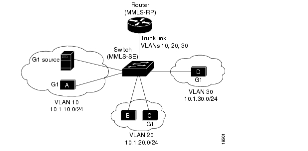
Figure 69 shows a basic IP multicast MLS example network topology.
Figure 69 Example Network: Basic IP Multicast MLS
The network is configured as follows:
•
•
•
•
•
•
–
–
–
Operation Before IP Multicast MLS Example
Without IP multicast MLS, when the G1 source (on VLAN 10) sends traffic destined for IP multicast group G1, the switch forwards the traffic (based on the Layer 2 multicast forwarding table entry generated by the IGMP snooping, CGMP, or GMRP multicast service) to Host A on VLAN 10 and to the router subinterface in VLAN 10.
The router receives the multicast traffic on its incoming subinterface for VLAN 10, checks the multicast routing table, and replicates the traffic to the outgoing subinterfaces for VLANs 20 and 30. The switch receives the traffic on VLANs 20 and 30 and forwards the traffic received on these VLANs to the appropriate switch ports, again based on the contents of the Layer 2 multicast forwarding table.
Operation After IP Multicast MLS Example
After IP multicast MLS is implemented, when the G1 source sends traffic destined for multicast group G1, the MMLS-SE checks its Layer 3 multicast MLS cache and recognizes that the traffic belongs to a multicast MLS flow. The MMLS-SE forwards the traffic to Host A on VLAN 10 based on the multicast forwarding table, but does not forward the traffic to the router subinterface in VLAN 10 (assuming a completely switched flow).
For each multicast MLS cache entry, the switch maintains a list of outgoing interfaces for the destination IP multicast group. The switch replicates the traffic on the appropriate outgoing interfaces (VLANs 20 and 30) and then forwards the traffic on each VLAN to the destination hosts (using the Layer 2 multicast forwarding table). The switch performs a packet rewrite for the replicated traffic so that the packets appear to have been routed by the appropriate router subinterface.
If not all the router subinterfaces are eligible to participate in IP multicast MLS, the switch must forward the multicast traffic to the router subinterface in the source VLAN (in this case, VLAN 10). In this situation, on those subinterfaces that are ineligible, the router performs multicast forwarding and replication in software, in the usual manner. On those subinterfaces that are eligible, the switch performs multilayer switching.
Note
Router Configuration
The following is an example configuration of IP multicast MLS on the router:
ip multicast-routinginterface fastethernet2/0.10encapsulation isl 10ip address 10.1.10.1 255.255.255.0ip pim dense-modeinterface fastethernet2/0.20encapsulation isl 20ip address 10.1.20.1 255.255.255.0ip pim dense-modeinterface fastethernet2/0.30encapsulation isl 30ip address 10.1.30.1 255.255.255.0ip pim dense-modemls rp ip multicast management-interfaceYou will receive the following message informing you that you changed the management interface:
Warning: MLS Multicast management interface is now Fa2/0.30Switch Configuration
The following example shows how to configure the switch (MMLS-SE):
Console> (enable) set trunk 1/2 on islPort(s) 1/2 trunk mode set to on.Port(s) 1/2 trunk type set to isl.Console> (enable) set igmp enableIGMP feature for IP multicast enabledConsole> (enable) set mls multicast enableMultilayer Switching for Multicast is enabled for this device.Console> (enable) set mls multicast include 10.1.10.1Multilayer switching for multicast is enabled for router 10.1.10.1.Complex IP Multicast MLS Network Examples
This example consists of the following sections:
•
•
•
•
•
Network Topology Example
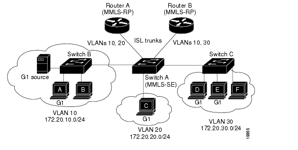
Figure 70 shows a more complex IP multicast MLS example network topology.
Figure 70 Complex IP Multicast MLS Example Network
The network is configured as follows:
•
•
•
•
•
•
•
•
•
•
•
–
–
–
•
–
–
–
•
•
•
•
Operation Before IP Multicast MLS Example
Without IP multicast MLS, when Server A (on VLAN 10) sends traffic destined for IP multicast group G1, Switch B forwards the traffic (based on the Layer 2 multicast forwarding table entry) to Host A on VLAN 10 and to Switch A. Switch A forwards the traffic to the Router A and Router B subinterfaces in VLAN 10.
Router A receives the multicast traffic on its incoming subinterface for VLAN 10, checks the multicast routing table, and replicates the traffic to the outgoing subinterface for VLAN 20. Router B receives the multicast traffic on its incoming interface for VLAN 10, checks the multicast routing table, and replicates the traffic to the outgoing subinterface for VLAN 30.
Switch A receives the traffic on VLANs 20 and 30. Switch A forwards VLAN 20 traffic to the appropriate switch ports (in this case, to Host C), based on the contents of the Layer 2 multicast forwarding table. Switch A forwards the VLAN 30 traffic to Switch C.
Switch C receives the VLAN 30 traffic and forwards it to the appropriate switch ports (in this case, Hosts D and E) using the multicast forwarding table.
Operation After IP Multicast MLS Example
After IP multicast MLS is implemented, when Server A sends traffic destined for multicast group G1, Switch B forwards the traffic (based on the Layer 2 multicast forwarding table entry) to Host A on VLAN 10 and to Switch A.
Switch A checks its Layer 3 multicast MLS cache and recognizes that the traffic belongs to a multicast MLS flow. Switch A does not forward the traffic to the router subinterfaces in VLAN 10 (assuming a completely switched flow). Instead, Switch A replicates the traffic on the appropriate outgoing interfaces (VLANs 20 and 30).
VLAN 20 traffic is forwarded to Host C and VLAN 30 traffic is forwarded to Switch C (based on the contents of the Layer 2 multicast forwarding table). The switch performs a packet rewrite for the replicated traffic so that the packets appear to have been routed by the appropriate router subinterface.
Switch C receives the VLAN 30 traffic and forwards it to the appropriate switch ports (in this case, Hosts D and E) using the multicast forwarding table.
If not all the router subinterfaces are eligible to participate in IP multicast MLS, the switch must forward the multicast traffic to the router subinterfaces in the source VLAN (in this case, VLAN 10). In this situation, on those subinterfaces that are ineligible, the routers perform multicast forwarding and replication in software in the usual manner. On those subinterfaces that are eligible, the switch performs multilayer switching.
Note
Router A (MMLS-RP) Configuration
ip multicast-routinginterface fastethernet1/0.1encapsulation isl 1ip address 172.20.1.1 255.255.255.0interface fastethernet1/0.10encapsulation isl 10ip address 172.20.10.1 255.255.255.0ip pim dense-modeinterface fastethernet1/0.20encapsulation isl 20ip address 172.20.20.1 255.255.255.0ip pim dense-modeRouter B (MMLS-RP) Configuration
ip multicast-routinginterface fastethernet1/0.1encapsulation isl 1ip address 172.20.1.2 255.255.255.0interface fastethernet2/0.10encapsulation isl 10ip address 172.20.10.100 255.255.255.0ip pim dense-modeinterface fastethernet2/0.30encapsulation isl 30ip address 172.20.30.100 255.255.255.0ip pim dense-modeSwitch A (MMLS-SE) Configuration
Console> (enable) set vlan 10Vlan 10 configuration successfulConsole> (enable) set vlan 20Vlan 20 configuration successfulConsole> (enable) set vlan 30Vlan 30 configuration successfulConsole> (enable) set trunk 1/1 on islPort(s) 1/1 trunk mode set to on.Port(s) 1/1 trunk type set to isl.Console> (enable) set trunk 1/2 on islPort(s) 1/2 trunk mode set to on.Port(s) 1/2 trunk type set to isl.Console> (enable) set trunk 1/3 desirable islPort(s) 1/3 trunk mode set to desirable.Port(s) 1/3 trunk type set to isl.Console> (enable) set trunk 1/4 desirable islPort(s) 1/4 trunk mode set to desirable.Port(s) 1/4 trunk type set to isl.Console> (enable) set igmp enableIGMP feature for IP multicast enabledConsole> (enable) set mls multicast enableMultilayer Switching for Multicast is enabled for this device.Console> (enable) set mls multicast include 172.20.10.1Multilayer switching for multicast is enabled for router 172.20.10.1.Console> (enable) set mls multicast include 172.20.10.100Multilayer switching for multicast is enabled for router 172.20.10.100.Console> (enable)Switch B Configuration
The following example shows how to configure Switch B assuming VLAN Trunking Protocol (VTP) is used for VLAN management:
Console> (enable) set igmp enableIGMP feature for IP multicast enabledConsole> (enable)Switch C Configuration
The following example shows how to configure Switch C assuming VTP is used for VLAN management:
Console> (enable) set igmp enableIGMP feature for IP multicast enabledConsole> (enable)
![]()
![]()
![]()
![]()
![]()
![]()
![]()
![]()
Posted: Tue Jul 25 04:42:24 PDT 2006
All contents are Copyright © 1992--2006 Cisco Systems, Inc. All rights reserved.
Important Notices and Privacy Statement.