|
|

This chapter defines the components of a Voice Routing Center (VRC) dial plan, their attributes, and how to use the components.
The Cisco VRC application provides an interface that allows you to:
This chapter contains the following sections:
 |
Note The AD must contain at least one managed region. |
You can view the general attributes of the AD in the:
The Attributes window displays the following fields:
The section describes how to manage the following AD parameters:
The route type is used to define the accepted configuration of the dial plan design and sets the route type for the entire Administrative Domain (AD).
|
Note You must be in the Design View to set the route type for the AD. |
To set the route type for the AD, follow these steps:
Step 1 Locate the AD in the list of elements. The Attributes tab is forward.
Step 2 To change or set the route type, click the Edit Attributes button. The Attributes for AD window appears.
Step 3 Set one of the following route types:
Step 4 Click Apply to select the CSR route type or click Cancel to cancel the procedure.
|
Note You must be in the Design View to add a technology prefix. |
To add a technology prefix to the AD, follow these steps:
Step 1 From the Design menu, click AD in the left pane.
Step 2 Click the Technology Prefixes tab. The technology prefixes table is displayed.
Step 3 Choose a technology prefix from the list and right-click on it.
Step 4 Choose Add from the menu. The Add Technology Prefix window appears (Figure 7-1).
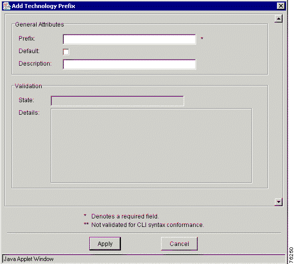
Step 5 Enter the technology prefix attribute information:
Step 6 Click Apply to apply this prefix to the gateway or click Cancel to cancel the procedure.
You can delete a technology prefix in an existing design or in a new design.
|
Note You must be in the Design View to delete a technology prefix. |
To delete a technology prefix from the AD, follow these steps:
Step 1 Choose either Open Design or New Design from the Design menu.
Step 2 Expand the AD to view all elements.
Step 3 Select the technology prefix you want to delete.
Step 4 Right-click and choose Delete from the menu. A confirmation dialog box appears asking you to confirm the deletion.
Step 5 Click OK to delete the technology prefix from the dial plan or click Cancel to cancel this procedure.
Trunk and carrier IDs connect a carrier identifier with each inbound call by associating the call on an inbound trunk group, NFAS group, or voice port with a defined carrier.
In VRC, a trunk carrier represents a carrier ID or trunk group label supported by the AD.
|
Note You must be in the Design View to add a trunk or carrier ID to the AD. |
To add a trunk or carrier ID to the AD, follow these steps:
Step 1 Expand the AD to view all elements.
Step 2 Click the Trunk/Carrier IDs tab.
Step 3 Right-click and choose Add from the menu. The Add Trunk/Carrier ID window appears (Figure 7-2).
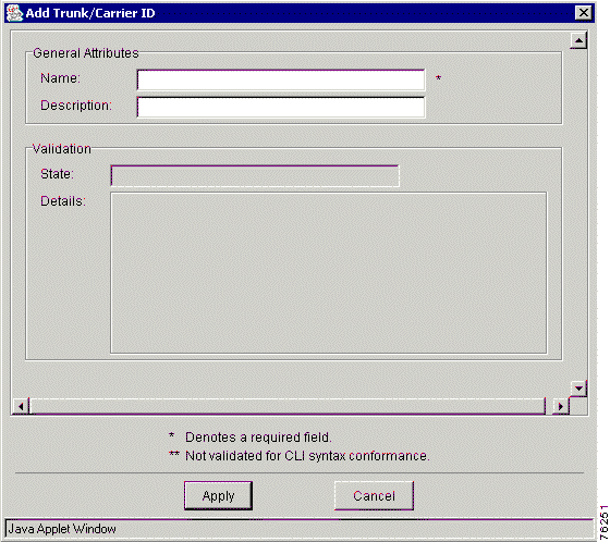
Step 4 Enter your values in the Name and Description fields.
Step 5 Click Apply to add the carrier or trunk ID to the AD or click Cancel to cancel this procedure.
A route server is external to the VRC managed dial plan. A VRC managed gatekeeper is configured to communicate with a route server (route servers are used across regions) through the use of server triggers which instruct the router to forward messages of a given route server type.
|
Note The AD must contain at least one route server. |
|
Note You must be in the Design View to add a route server to the AD. |
To add a route server to the AD, follow these steps:
Step 1 Right-click the AD.
Step 2 Choose Add and Route Server from the menu. The Add Route Server window appears.
Step 3 Enter the following information:
Step 4 Click Apply to add the route server to the AD or click Cancel to cancel the procedure.
A region is a logical division of the Administrative Domain (AD).
This section contains the following topics about a region:
The VRC application supports:
A region is either meshed or hierarchical.
The following VRC views allow you to view general attributes of selected regions:
A managed region might contain:
Table 7-1 describes the attributes that you must define for a managed region.
| Entry Field | Description |
|---|---|
Name | The name of the region. The maximum value is 64 characters. |
Domain | The domain name. The maximum value is 255 characters. |
Class | The class of the region. Choose meshed or hierarchical. The default is meshed. If you specify a meshed region, you cannot add directory gatekeeper groups to this region. |
Default LRQ Password | The LRQ password used by all elements in this region to trap LRQs from unknown remote zones. Choose from a previously defined list of LRQ passwords. The maximum value is 1023 characters. Note A default regional LRQ password is required before any other security feature can be used. The default LRQ password creates a "catch all" clause for all regional gatekeepers and directory gatekeepers. Note If you set this parameter, you must have an incoming connection for every region that has an outgoing connection pointing to it. |
Status | The validation status of the region. |
Details | An optional text string that gives more details about the status of the region. The maximum value is 255 characters. |
Table 7-2 describes the attributes that you must define for a foreign region.
| Entry Field | Description |
|---|---|
Name | The name of the region. The maximum value is 64 characters. |
Domain | The domain name. The maximum value is 255 characters. |
IP Address | The IP address of the gatekeeper, which is the point of contact for this foreign region. |
RAS Port | The Registration, Admission, and Status signaling port. The range is 1 to 65535. |
Status | The validation status of the region. |
Details | An optional text string that gives more details about the status of the region. The maximum value is 255 characters. |
You can also add a region to the topology using a batch import file:
|
Note You must be in the Topology View to add a region to the topology. |
To add a region to the topology from the Topology View, follow these steps:
Step 1 Choose Open Topology from the Topology menu. There are two tabs at the top of the Topology View pane: Regions tab and the Elements tab.
Step 2 Click the Regions tab. The regions that already exist in the dial plan are listed in the table (Figure 7-3).
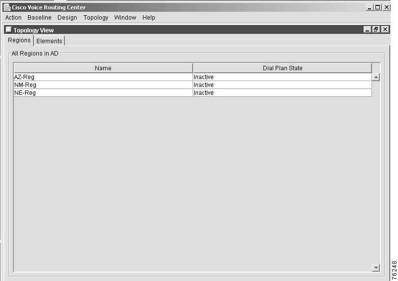
Step 3 Right-click in the region window and choose Add from the menu. The Topology Add/Modify Region window appears.
Step 4 Enter the name of the managed region that you want to add.
Step 5 Click OK to add the new region name or click Cancel to cancel the procedure.
|
Note The dial plan state of the region remains inactive until you commit the dial plan design that contains the region. |
|
Note The region must exist in the topology before you can add it to the dial plan. |
To add a managed region to a dial plan, follow these steps:
Step 1 Expand the AD to view all elements.
Step 2 Choose Add and then choose Managed Region from the menu. The Add Managed Region to Dial Plan window appears with a list of available regions.
Step 3 Select the region that you want to add to the dial plan.
Step 4 Click Apply to add the region to the dial plan or click Cancel to cancel the procedure.
To add a foreign region to a dial plan, follow these steps:
Step 1 Expand the AD to view all elements.
Step 2 Choose Add and then choose Foreign Region from the menu. The Add Foreign Region window appears (Figure 7-4).
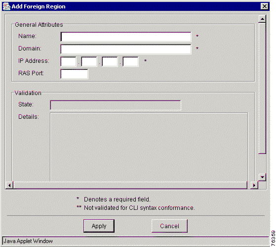
Step 3 Enter the values in the entry fields. The entry fields are described in Table 7-2.
Step 4 Click Apply to add the region to the dial plan or click Cancel to cancel the procedure.
This section describes how to delete a region from the AD. You can delete a region from:
|
Note You must be in the Topology View to delete a region from the topology. You can only delete inactive regions from the topology. Regions are inactive if all elements in the region are in the inactive state. |
To delete a region from the topology, follow these steps:
Step 1 From the Topology menu, choose Open Topology and click the Regions tab.
Step 2 Select the region that you want to delete. Right-click the region and choose Delete from the menu.
The Topology Delete Region dialog box appears asking you to confirm the delete operation.
Step 3 Click OK to delete the region or click Cancel to cancel the procedure.
|
Note When you remove a region from the dial plan, you remove all elements contained in that region. |
|
Note You must be in the Design View to delete a region from the dial plan. |
To remove a region from the dial plan design, follow these steps:
Step 1 Expand the AD to view all elements.
Step 2 Select the region that you want to delete.
Step 3 Right-click the region and choose Delete from the menu.
A Confirm dialog box appears asking you to confirm the delete operation.
Step 4 Click Disable to delete the region, click Do Not Disable, or click to Cancel the procedure.
This section describes how to add or delete the following region parameters:
Regions own their outgoing connections. You can choose the other regions to receive communication from them. These outgoing connections become the incoming connections of the receiving region. VRC allows you to add and delete outgoing connections to a region.
|
Note If you set the Default LRQ password attribute for a given region, you must have an incoming connection for every region that has an outgoing connection pointing to it. |
|
Note You can add outgoing connections to managed regions and foreign regions. |
|
Note You must be in the Design View to add outgoing connections for a region. |
To add an outgoing connection for a region, follow these steps:
Step 1 Expand the AD to view all regions.
Step 2 Locate a region that you want to add an outgoing connection to.
Step 3 Click the Outgoing Connections tab. The right pane displays the regions and their associated outgoing connections.
Step 4 Right-click on that region and choose Add from the menu. The Add Connection dialog box appears.
Step 5 Select a 'connection to' region from the drop-down list.
|
Note If your 'connection to region' is a foreign region, set the LRQ password, if it is known. |
Step 6 Click Apply to apply the outgoing connection to the region or click Cancel to cancel the procedure.
|
Note You must be in the Design View to delete outgoing connections for a region. |
To delete an outgoing connection from a managed region, follow these steps:
Step 1 Expand the AD to view all regions.
Step 2 Select a region that you want to delete the outgoing connection from.
Step 3 Click the Outgoing Connections tab. The window displays the regions and their associated outgoing connections.
Step 4 Select a 'connection to' region.
Step 5 Right-click on the selected region and choose Delete from the menu. A Confirm dialog box appears.
Step 6 Click OK to confirm the delete or click Cancel to cancel the procedure.
A voice class codec is the coding scheme used for outgoing calls. VRC allows the administrator to select a valid voice encoding or decoding scheme from its list. You can add or delete voice class codecs from a managed region. A codec is the voice coder rate of speech for a dial peer.
|
Note You must be in the Design View to add a voice class codec. |
To add voice class codecs to a managed region, follow these steps:
Step 1 Expand the AD to view all elements.
Step 2 Locate the region that you want to add the voice class codec to.
Step 3 Click the Voice Class Codecs tab. The window displays the voice class codecs associated with this region.
Step 4 Right-click and choose Add from the menu. The Add Voice Class Codecs window appears.
Enter the voice class codec attribute values in the following fields:
Step 5 Click Apply to add the voice class codec or click Cancel to cancel the procedure.
|
Note You must be in the Design View to add a voice class codec. |
To delete voice class codecs to a managed region, follow these steps:
Step 1 Expand the AD to view all elements.
Step 2 Locate the region that you want to delete the voice class codec from.
Step 3 Click the Voice Class Codec tab. The window displays the voice class codecs associated with this region.
Step 4 Right-click and choose Delete from the menu. A Confirm dialog box appears.
Step 5 Click OK to confirm the deletion or click Cancel to cancel the procedure.
A codec is a software algorithm used to compress/decompress speech or audio signals in Voice-over-IP (VoIP) networks.
|
Note You must be in the Design View to add a codec to a voice class codec. |
To add a codec option to a voice class codec in a region, follow these steps:
Step 1 Expand the AD to view all elements.
Step 2 Locate the region which contains the voice class codec you want to add a codec to.
Step 3 Click the Voice Class Codecs tab.
Step 4 Double-click the voice class codec you want to add a codec to.
Step 5 Click the Codecs tab.
Step 6 Right-click and choose Add from the menu. The Add Codec window appears (Figure 7-5).
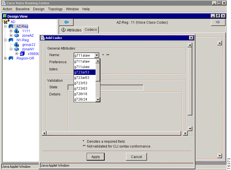
Enter the attribute information in the following fields:
|
Note Not all codecs are available on all gateway platforms. Check the Cisco IOS version on your gateway to see which codecs are supported. |
| Codec Option | Description |
|---|---|
g711alaw | G.711 a-Law at 64,000 bits per second (bps) |
g711ulaw | G.711 u-Law at 64,000 bps |
g723ar53 | G.723.1 Annex A at 5300 bps |
g723ar63 | G.723.1 Annex A at 6300 bps |
g723r53 | G.723.1 at 5300 bps |
g723r63 | G.723.1 at 6300 bps |
g726r16 | G.726 at 16,000 bps |
g726r24 | G.726 at 24,000 bps |
g726r32 | G.726 at 32,000 bps |
g728 | G.728 at 16,000 bps |
g729br8 | G.729 Annex A and B at 8000 bps |
g729r8 | G729 Annex A at 8000 bps |
gsmcfr | 12200 bps |
gsmfr | 13200 bps |
Step 7 Click Apply to add the codec or click Cancel to cancel the procedure.
LRQ passwords represent CAT (Cisco Access Token) exchanged between two gatekeepers or directory gatekeepers, while forwarding an LRQ.
|
Note We recommend that you use Network Time Protocol (NTP) when you use LRQ passwords in VRC. Elements that exchange CAT must use NTP for authentication to succeed. |
LRQ Passwords can be created by a regional administrator and are associated with all LRQ paths in the network. VRC ensures that passwords are correctly configured on both the sending and the receiving end.
LRQ passwords:
You can only add an LRQ password for a given region if the Default LRQ password attribute is set for that region.
|
Note You must be in the Design View to add an LRQ password to a region. |
To add an LRQ password to a region, follow these steps:
Step 1 Expand the AD to view all elements.
Step 2 Locate the region that you want to add an LRQ password to.
Step 3 Click the LRQ Passwords tab. The window displays the LRQ passwords associated with this region.
Step 4 Right-click and choose Add from the menu. The Add LRQ Password dialog box appears (Figure 7-6).
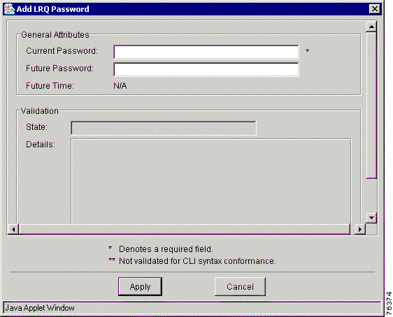
Step 5 Enter the LRQ attribute information:
Step 6 Click Apply to add the LRQ password to the region or click Cancel to cancel the procedure.
You must delete all references to an LRQ password before you can delete it (for example, in incoming and outgoing connections).
|
Note You must be in the Design View to delete an LRQ password. |
To delete an LRQ password from a region, follow these steps:
Step 1 Expand the AD to view all regions.
Step 2 Locate the region you want to delete an LRQ password from.
Step 3 Click the LRQ Passwords tab. The window displays the regions and their associated LRQ passwords.
Step 4 Select the LRQ password that you want to delete from this region.
Step 5 Right-click and choose Delete from the menu. You are asked to confirm your decision.
Step 6 Click OK to delete the LRQ password from the region or click Cancel to cancel the procedure.
An incoming region connection represents the unidirectional connection from one region to the owner region. The incoming region owns the LRQ password associated with the connection.
You must set up an LRQ password before you can add an incoming region connection to a region.
|
Note If you set the Default LRQ password attribute for a given region, you must have an incoming connection for every region that has an outgoing connection pointing to it. |
|
Note You must be in the Design View to add an incoming region connection. |
To add an incoming region connection from one region in the AD to another, follow these steps:
Step 1 Expand the AD to view all regions.
Step 2 Locate the region that you want to add an outgoing connection to.
Step 3 Click the Incoming Connections tab. The window displays the outgoing connections associated with this region.
Step 4 Right-click and choose Add from the menu.
Step 5 Select a 'Connection To' region from the drop-down list.
Step 6 Select the LRQ Password. This is the password used to validate any LRQs received from the specified remote zone.
|
Note For inter-region communication, the LRQ password must be associated with an incoming region connection. If it is not set, the default regional password is used. |
Step 7 Click Apply to add the incoming region connection to the owner region or click Cancel to cancel the procedure.
|
Note You must be in the Design View to delete an incoming region connection. |
To delete an incoming connection from a managed region, follow these steps:
Step 1 Expand the AD to view all regions.
Step 2 Locate the region you want to delete an outgoing connection from.
Step 3 Click the Outgoing Connections tab. The window displays the regions and their associated outgoing connections.
Step 4 Select the 'Connection To' region you want to delete from this connection.
Step 5 Right-click and choose Delete from the menu. You are asked to confirm your decision.
Step 6 Click OK to delete the outgoing connection from the region or click Cancel to cancel the procedure.
This section contains the following topics about elements:
In the VRC dial plan, the element states refer to their status in the VRC dial plan, availability to the Discovery operation, and the status of the running configuration in relation to the startup configuration.
There are two types of element states:
During the Discovery operation, all elements in the topology which have an Assigned state are added to the discovery design session. If you want to perform a Discovery on a specific network element with an Assigned state, the element is put into the discovery design session. If the element is Unassigned, discovery cannot take place.
Network elements can be gateways, gatekeepers, or directory gatekeepers. To add an element to a dial plan, refer to the specific element.
You must have valid user permissions and you must be in the Topology View to add an element to the network topology.
|
Note You must open a design session to add elements to a dial plan. |
To add an element to the network topology, follow these steps:
Step 1 Access the Topology View. There are two tabs at the top of the Topology View pane: Regions and Elements.
Step 2 Click the Elements tab.
Step 3 Select a region from the drop-down menu. The elements that already exist in that region are listed in the table.
Step 4 Right-click the element and choose Add from the menu. The Topology—Add/Modify Element window appears (see Figure 7-7).
Step 5 Enter the element attribute information. For information on element entry fields, see Viewing Element Details.
Table 7-4 describes the element password attributes.
| Attribute | Description |
|---|---|
User Password | The authorization password. |
Enable Password | Password required to enter Enable mode. |
Line Password | Telnet password required to set up a remote session into the element. |
Enable Secret Password | Optional password allows access to the element. |
Step 6 When you are finished entering information, click OK to add the new element to the region or click Cancel to cancel the procedure.
|
Note You must be in the Topology View to view element details. |
To view element attributes, follow these steps:
Step 1 Click the Elements tab.
Step 2 Select the region from the drop-down menu.
Step 3 Select the element that you want to view.
Step 4 Right-click the selected element and choose Details from the menu. The Topology—View Element window appears (Figure 7-7).
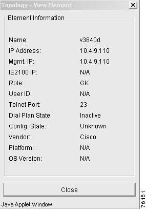
Table 7-5 describes the attributes of the selected element in the Topology—View Element window.
| General Attributes | Description |
|---|---|
Name | The host name of the element. If the name is not entered, the VRC server contacts the element and gets the host name during discovery or distribution. |
IP Address | The voice-enabled IP address used for H323 protocol. |
Mgmt. IP Address | IP address used to administer the element. |
IE2100 IP | IP address for the Cisco IE2100 device if you have one configured as part of your network. |
Role | Indicates the role of the element. It can be a gateway, gatekeeper, or directory gatekeeper. |
User ID | Used with the Secret Password to access the element. |
Telnet Port | This port with the management IP address is used to administer the element. The default value for this field is 23. |
Dial Plan State | The state of the element in the dial plan. Values are:
|
Configuration State | The state of the running configuration. Values are:
Note When you first add an element, that element is in the unknown state. |
Vendor | The manufacturer of the element is Cisco. |
Platform | The platform of the element. |
IOS Version | Indicates the Cisco IOS release version of the element. |
|
Note You cannot view element passwords from this window. You must have user permissions to modify element information. |
Step 5 Click Close to close the window when you are finished viewing the element information.
To modify an element, you must have dial plan administrative privileges.
|
Note You must be in the Topology View to modify an element. |
To modify an element, follow these steps:
Step 1 Click the Elements tab.
Step 2 Select a region from the drop-down menu. The elements that already exist in that region are listed in the table.
Step 3 Right-click the selected element and choose Modify from the menu. The Topology Add/Modify Element window appears (see Figure 7-7).
Step 4 Enter the element information that you want to change. For an explanation of passwords, see Adding an Element. For information about the other entry fields, see Viewing Element Details.
Step 5 Click OK to add the element to the region or click Cancel to cancel the procedure.
|
Note You can also update the element information as you make changes. From the Window menu, choose Refresh Display. |
|
Note You must be in the Topology View to move an element. |
|
Note The element must be inactive before you can move it. |
To move an element, follow these steps:
Step 1 Click the Elements tab.
Step 2 Select a region from the drop-down menu. The elements that already exist in that region are listed in the table.
Step 3 Right-click the selected element and choose Move from the menu. The Topology—Move Element window appears (Figure 7-8).
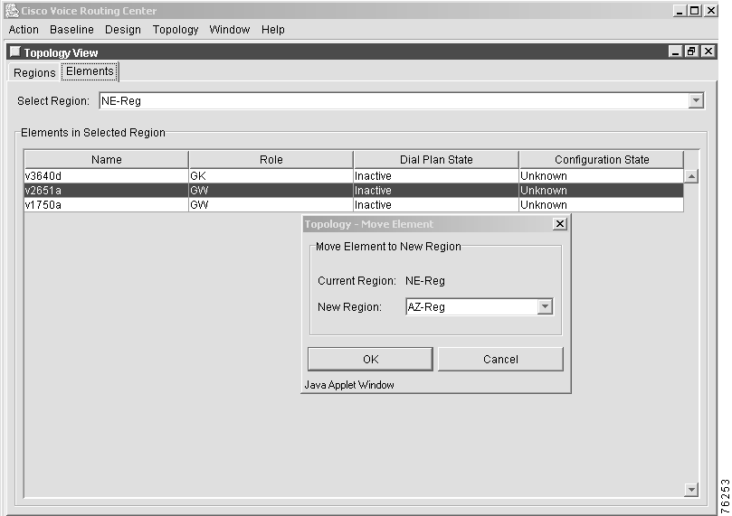
Step 4 Select a new region from the drop-down list to move the element to.
Step 5 Click OK to move element to the new region or click Cancel to cancel the procedure.
You can only delete network elements from the topology if the element is not part of the current baseline dial plan or if the element is not being used in a design session. The dial plan state must be Inactive before you can delete it from the topology.
To only remove the element from the dial plan but not from the topology, see Removing an Element from the Dial Plan.
|
Note You must be in the Topology View to delete an element. |
To delete an element, follow these steps:
Step 1 Click the Elements tab.
Step 2 Select a region from the drop-down menu. The elements that already exist in that region are listed in the table.
Step 3 Right-click the selected element and choose Delete from the menu. The Topology—Delete Element confirmation dialog box appears.
Step 4 Click OK to delete the element or click Cancel to cancel the procedure.
Use the Remove operation to only remove the element from the dial plan but not from the topology.
|
Note You must be in the Design View to remove an element from the dial plan. |
To remove an element, follow these steps:
Step 1 Expand the AD to show all elements.
Step 2 Right-click the element that you want to remove and choose the Remove from Dial plan option. A confirmation dialog box appears.
Step 3 Choose either Disable or Do not Disable. If you choose:
Step 4 Click OK to remove the element or click Cancel to cancel the procedure.
You can persist the configuration of a single element or all elements in a region.
If you persist:
|
Note You must be in the Topology View to persist the configuration of an element. |
To use the persist operation for a single element, follow these steps:
Step 1 From the Topology View, click the Elements tab.
Step 2 Select a region from the drop-down list. The elements in that region are listed in the table.
Step 3 Right-click the selected element and choose Persist from the menu.
Step 4 Click OK to display the new configuration state in the Topology View. VRC writes the running configuration of the element to the startup configuration.
To use the persist operation for all elements in a region, follow these steps:
Step 1 Click the Regions tab.
Step 2 Right-click in the region window and choose Persist All from the menu.
VRC writes the running configuration to the startup configuration for all elements in that region.
An information dialog box appears informing you that the operation is successful.
Step 3 Click OK to confirm the persist operation or click Cancel to cancel the operation.
You can check the accesibility of network elements within a selected scope.
|
Note You must be in the Design View to check element accessibility. |
To check on elements, follow these steps:
Step 1 Expand the AD to view all elements.
Step 2 Select the elements that you want to check the accessibility for. You can check a group of elements within a particular scope.
Step 3 Right-click the selected element and choose Check Elements from the menu.
Step 4 Choose which elements that you want to check accessibility for. Select:
Step 5 You are asked to confirm your decision. Click OK.
A Checking Elements dialog box informs you that the operation is in progress. Once the checking has finished, an information dialog box (Figure 7-9) appears, telling you that the operation was successful.
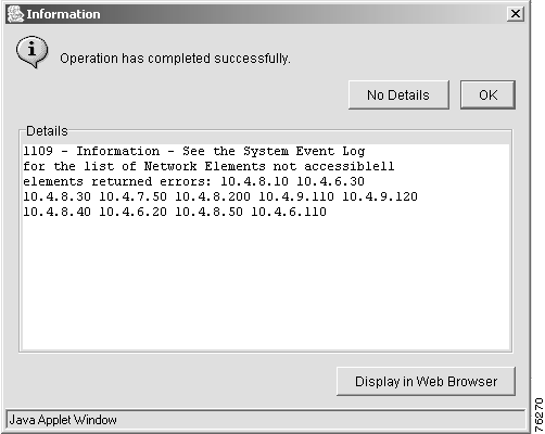
Step 6 Click OK to close the window, click Details to view detailed information, click No Details to hide the information, or click Display Web Browser to open a web browser window to view the information.
When you add a network element to a dial plan design, that element is implicitly activated.
You can reactivate the element using the VRC client any time you suspect that there have been changes to element configuration information using the command line interface (CLI) directly.
|
Note You must be in the Design View to reactivate an element. |
To reactivate a gateway, gatekeeper, or directory gatekeeper, follow these steps:
Step 1 Expand the AD to view all elements.
Step 2 Select the element for reactivation.
Step 3 Right-click the element and choose Reactivate from the menu.
VRC updates the dial plan configuration information for that element.
VRC supports the use of Cisco IE2100 and the Cisco Network Security (CNS) configuration server to deliver configurations to network devices.
To use a Cisco IE2100 to access elements in your network, you must configure the device outside of VRC. A large network might have multiple Cisco IE2100 devices.
|
Note You must have the CNS Event Bus installed and running to use a Cisco IE2100 device in your network. |
A directory gatekeeper group (DGKGrp) is a set of one to five directory gatekeepers (DGKs) depending on the group type, that you configure for redundancy. This configuration is based on primary, none, Hot Standby Router Protocol (HSRP), cluster, or overlap directory gatekeepers (see Table 7-6).
You can add server triggers and zone circuits to a directory gatekeeper group.
|
Note You can only add a zone circuit to a directory gatekeeper group if the CSR route type is set to trunk-label or carrier and the VRC feature set is dp1.1. |
This section describes the following topics:
You can view the general attributes of a selected directory gatekeeper group (DGKGrp) from the Baseline View or the Design View:
|
Note Enhanced functionality attributes can only be viewed and edited if the VRC feature set for this directory gatekeeper group is set to dp1.1. |
Table 7-6 describes the attributes of a directory gatekeeper group.
| General Attributes | Description |
|---|---|
Name | The name of the directory gatekeeper group. The maximum value is 64 characters. |
Cluster Name | The local cluster name assigned by this directory gatekeeper group, if it is configured as clustered. The maximum value is 64 characters. |
RAS Port | The registration, admission, and status signaling port. The range is 1 to 65535. The default is 1719. |
Type | The type of redundancy system used for this directory gatekeeper group. The default is none.
|
Feature Set | The VRC feature set supported by this directory gatekeeper group. Choose from dp1.0 or dp1.1. The default is dp1.0. |
Timeout | The timer server timeout (100-ms units). The default is none. The range is 1 to 50. |
IRR Timer | Sets the IRR reporting interval which it sets on the gateway upon the gateway's registration. This value can only be set if the VRC feature set is dp1.1. The range is 1 to 60. |
Server Registration Port | Configures a port for the gatekeeper to communicate with a Gatekeeper Transaction Message Protocol (GKTMP) server. The range is 1 to 65535. |
Server Flow Enabled | Check this box if you want to enable flow control from the VRC server to the network device. The server flow control monitors the average response time from the server to the GKTMP. |
Server Flow High | Can only be set if server flow is enabled. The onset percentage of the timeout value used to mark the server as usable or unusable. The range is 1 to 100. The default is 80. |
Server Flow Low | Can only be set if server flow is enabled. The abatement percentage of the timeout value used to mark the server as usable or unusable. The range is 1 to 100. The default is 50. |
Max. Queue Length | Can only be set if server flow is enabled. The threshold for the length of the outbound queue on the gatekeeper. The TCP socket between the gatekeeper and GKTMP server queues messages if it has too many to transmit. If the count of outbound queue length on the server reaches this value, the server is marked unusable. The range is 1 to 2000. The default is 50. |
Server Retry Timer | Specifies the interval (in seconds) to wait between the detection of a server failure and the next attempt to connect to the failed server. This value can only be set if the VRC feature set is dp1.1. The range is 1 to 300. |
Disable IRQ Global Request | Disables global request or call reference value (CRV) set to zero for newly registering end-points. This value can only be set if feature set is dp1.1. |
LRQ Reject Unknown Circuit | Enables directory gatekeeper rejection of LRQ messages that contain unknown destination carrier IDs descriptions. This value can only be set if the VRC feature set is dp1.1 and the CSR route type is carrier or trunk-label. |
Disable LRQ Immediate Advance | Disables the gatekeeper from immediately sending a sequential location request (LRQ) to the next zone after it receives a location reject (LRJ) from a gatekeeper in the current zone. |
LRQ Reject Resource Low | If this parameter is set, the gatekeeper rejects the inter-zone call if all gateways in that zone are marked as almost-out-of-resources. |
LRQ Receive Password | The LRQ password that the directory gatekeeper assigns to the zones. Set this password to specify an internal regional password for directory gatekeeper communication. If it is not set, the default regional password is used. |
ICZT Password | Enables generation of the interzone ClearToken (ICZT) password. The range is 6 to 8 alphanumeric characters. You can only set this parameter if the VRC feature set is dp1.1. |
| LRQ Handling Description | |
LRQ Reject Unknown | Rejects LRQ messages for unknown zone prefixes. |
LRQ Forwarding | Forwards E.164 Location Request (LRQ) messages to remote gatekeepers managing that zone prefix. Values are:
Note VRC does not support simultaneous LRQs being sent on a gatekeeper for a specific zone prefix (LRQ blast), when multiple gatekeepers have the same prefix. |
LRQ Delay | Time interval between successive LRQ messages (100-ms units). The range is 1 to 10. |
LRQ Window | Defines the time window (in seconds) during which the gatekeeper collects responses to one or more outstanding LRQs. The range is 1 to 15. |
Use this procedure to add a new directory gatekeeper group (DGKGrp) to a managed region.
|
Note You must be in the Design View to add a directory gatekeeper group. |
|
Note You can only add one directory gatekeeper group to a hierarchical region. You cannot add directory gatekeeper groups to meshed regions. |
To add a directory gatekeeper group, follow these steps:
Step 1 Expand the AD to view all elements.
Step 2 Select and right-click the managed region that you want to add a directory gatekeeper group to.
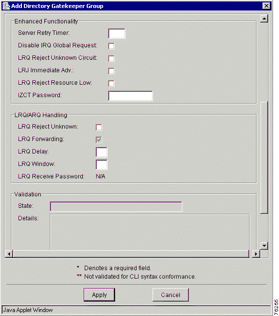
Step 3 Choose the Add and Directory Gatekeeper Group options from the menus. The Add Directory Gatekeeper Group window appears.
|
Note See Figure 7-10 for General Attributes and Figure 7-11 for Enhanced Functionality and LRQ/ARQ Handling. |
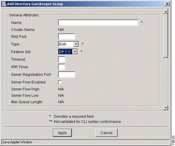
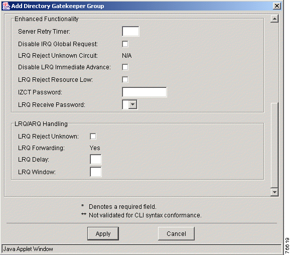
Step 4 Enter the attribute values. Refer to Table 7-6 for descriptions.
Step 5 Click Apply to add a new directory gatekeeper group or click Cancel to cancel the procedure.
|
Note You must be in the Design View to delete a directory gatekeeper group from the dial plan. |
To delete a directory gatekeeper group, follow these steps:
Step 1 Expand the AD to view all elements.
Step 2 Locate the directory gatekeeper group that you want to delete.
Step 3 Right-click the directory gatekeeper group and choose the Delete option from the menu.
Step 4 You are asked to determine the status of the dial plan configuration:
Step 5 Click OK to remove the directory gatekeeper group and child elements from the dial plan or click Cancel to cancel the procedure.
|
Note VRC does not support simultaneous LRQs being sent on a gatekeeper for a specific zone prefix (LRQ blast), when multiple gatekeepers have the same prefix. |
A directory gatekeeper:
The directory gatekeeper routes calls outside the local zones by maintaining a list of zone prefix routing tables.
The following Cisco platforms are recognized as directory gatekeepers in VRC:
You can view the general attributes of a selected directory gatekeeper (DGK) from the Design View or Baseline View:
Table 7-7 describes the attributes of a directory gatekeeper.
| General Attributes | Description |
|---|---|
Name | The name of the directory gatekeeper. The maximum value is 64 characters. |
IP Address | IP address of the directory gatekeeper. |
Standby IP | The IP address the directory gatekeeper uses to communicate with the directory gatekeeper group if the directory gatekeeper group is configured for HSRP. |
Feature Set | The VRC feature set supported by this directory gatekeeper. This field is populated by VRC when the directory gatekeeper is added to the dial plan. |
IOS version | The Cisco IOS version running on this directory gatekeeper. |
Local Zone Name | The name of the local zone that is associated with this directory gatekeeper. The maximum value is 255 characters. |
Type | The type of directory gatekeeper. Choose from primary, overlap, cluster, or backup. The default is primary. You can have only one primary and only one overlap directory gatekeeper in a directory gatekeeper group (DGKGrp). If you choose:
|
Server Flow High | This read-only field is populated by VRC during the Discovery operation. |
Server Flow Low | This read-only field is populated by VRC during the Discovery operation. |
Max. Queue Length | This read-only field is populated by VRC during the Discovery operation. |
Status | Indicates whether the Cisco VRC server can contact the element. Values are:
|
Details | An optional text string that gives more details about the status of the element. The maximum value is 255 characters. |
Use this procedure to add a directory gatekeeper to a directory gatekeeper group in the dial plan.
|
Note You must be in the Design View to add a directory gatekeeper to a directory gatekeeper group. |
|
Note You can only add a directory gatekeeper to a directory gatekeeper group for a hierarchical region. There are no directory gatekeeper groups for meshed regions. |
|
Note When you add an element to the dial plan, any preexisting dial plan configuration for that element is overwritten when you commit the design. |
To add a new directory gatekeeper, follow these steps:
Step 1 Expand the AD to view all elements.
Step 2 Locate the directory gatekeeper group you want to add a directory gatekeeper to.
Step 3 Right-click the selected directory gatekeeper group.
Step 4 Choose the Add option and Directory Gatekeeper from the menu. The Add New Directory Gatekeeper to Dial plan dialog box appears. This dialog box lists the IP addresses of available directory gatekeepers.
Step 5 Select a directory gatekeeper and click the Add button. The directory gatekeeper is added to the dial plan. A confirmation dialog box appears. You are prompted when the operation is successful.
Step 6 Click OK to add a directory gatekeeper to the dial plan or click Cancel to cancel the procedure.
To delete a directory gatekeeper (DGK) from the:
A gatekeeper group is a dial plan entity composed of one or more physical gatekeepers.
One gatekeeper in each gatekeeper group must be designated as the primary gatekeeper. If a gatekeeper group contains more than one gatekeeper, you must configure the gatekeepers in a redundant manner using one of the following supported techniques:
|
Note You can only add a zone circuit to a gatekeeper group if the CSR route type is set to trunk-label or carrier and the VRC feature set is dp1.1. |
You can view the general attributes of a selected directory gatekeeper group (GKGrp) in the Design View or the Baseline View:
|
Note You can only add a zone circuit to a gatekeeper group if the CSR route type is set to trunk-label or carrier and the VRC feature set is dp1.1. |
|
Note Enhanced functionality attributes can only be viewed and edited if the VRC feature set for this directory gatekeeper group is set to dp1.1. |
Table 7-8 describes the attributes of a gatekeeper group.
| General Attributes | Description |
|---|---|
Name | The name of the gatekeeper group. The maximum value is 64 characters. |
RAS Port (Registration, Admission, Status) | The port that performs registration, admission, and status signaling. The range is 1 to 65535. The default is 1719. |
Type | The type of redundancy system used for this gatekeeper group. The default is none. Values are:
|
Feature Set | The VRC feature set supported by this gatekeeper group. Choose from dp1.0 or dp1.1. The default is dp1.0. |
Timeout | The server timeout for Gatekeeper Transaction Message Protocol (GKTMP) messages. The range is 1 to 50. |
Server Registration Port | Configures a port for the gatekeeper to communicate with a GKTMP server. The range is 1 to 65535. |
Tech Prefix | Special characters to be included in the called number. Select from the list of predefined technology prefixes. |
Server Flow Enabled | Check this box if you want to enable flow control from the VRC server to the network device. The server flow control monitors the average response time from the server to the GKTMP. |
Server Flow High | Can only be set if server flow is enabled. The onset percentage of the timeout value used to mark the server as usable or unusable. The range is 1 to 100. The default is 80. |
Server Flow Low | Can only be set if server flow is enabled. The abatement percentage of the timeout value used to mark the server as usable or unusable. The range is 1 to 100. The default is 50. |
Max. Queue Length | Can only be set if server flow is enabled. The threshold for the length of the outbound queue on the gatekeeper. The TCP socket between the gatekeeper and GKTMP server queues messages if it has too many to transmit. If the count of outbound queue length on the server reaches this value, the server is marked unusable. The range is 1 to 2000. The default is 50. |
Enhanced Functionality | |
ICZT Password | Enables generation of the interzone ClearToken (IZCT) password. The range is 6 to 8 alphanumeric characters. You can only set this parameter if the VRC feature set is dp1.1. |
IRR Timer | Sets the IRR reporting interval which it sets on the gateway upon the gateway's registration. This value can only be set if the VRC feature set is dp1.1. The range is 1 to 60. |
Server Retry Timer | Specifies the interval (in seconds) to wait between the detection of a server failure and the next attempt to connect to the failed server. This value can only be set if the VRC feature set is dp1.1. The range is 1 to 300. |
Disable IRQ Global Request | Disables global requests or call reference values (CRVs) set to zero for newly registering end-points. This value can only be set if the VRC feature set is dp1.1. |
Enable Server Absent Reject RRQ | Configures the gatekeeper to reject new registration calls or calls when the connection to the Gatekeeper Transaction Message Protocol (GKTMP) server is down. |
Enable Server Absent Reject ARQ | Configures the gatekeeper to reject admission requests when the connection to the GKTMP server is down. |
LRQ Reject Unknown Circuit | Enables gatekeeper rejection of location request (LRQ) messages that contain unknown destination carrier IDs descriptions. This value can only be set if the VRC feature set is dp1.1 and the CSR route type is carrier or trunk-label. |
Disable LRQ Immediate Advance | Disables the gatekeeper from immediately sending a sequential LRQ to the next zone after it receives a location reject (LRJ) from a gatekeeper in the current zone. |
LRQ Reject Resource Low | If this parameter is set, the gatekeeper rejects the inter-zone call if all gateways in that zone are marked as almost-out-of-resources. |
High Resource Threshold | Sets high call volume thresholds in the gatekeeper for monitoring its gateway. The range is 1 to 99. This value can only be set if the VRC feature set is dp1.1. |
Low Resource Threshold | Sets low call volume thresholds in the gatekeeper for monitoring its gateway. The range is 1 to 99. This value can only be set if the VRC feature set is dp1.1. |
LRQ Receive Password | The LRQ password that the gatekeeper assigns to the zones. Set this password to specify an internal regional password for gatekeeper communication. If it is not set, the default regional password is used. |
LRQ/ARQ Handling | |
LRQ Reject Unknown | Rejects LRQ messages for unknown prefixes. |
ARQ Reject Unknown | Rejects ARQ messages for unknown prefixes. |
LRQ Forwarding | Forwards E.164 LRQ messages to remote gatekeepers managing that zone prefix. Values are:
Note VRC does not support simultaneous LRQs being sent on a gatekeeper for a specific zone prefix (LRQ blast), when multiple gatekeepers have the same prefix. |
LRQ Delay | Time interval between successive LRQ messages (100-ms units). The range is 1 to 10. |
LRQ Window | Defines the time window (in seconds) during which the gatekeeper collects responses to one or more outstanding LRQs. The range is 1 to 15. |
Security | |
Security Level | The security level. Choose from registration or all. The default is no security level. |
Security Type | Enable authentication and authorization on a gatekeeper. Choose from any, h323id, or e164. The default is no security type. |
Security Password | The default password that the gatekeeper associates with endpoints when authenticating them with an authentication server. The maximum value is 20 characters. |
Separator | The character that endpoints use to separate the H.323-ID from the piggybacked password in the registration. The character is null if H.323 is not used. The value must be one character. |
| Resource Management | |
Load Balance | Specifies whether this gatekeeper group is configured for load sharing between the gatekeepers. |
Max. Endpoints | Maximum number of endpoints. The range is 0 to 2147483647. |
Max. Calls | Maximum number of calls. The range is 0 to 2147483647. |
Max. CPU | Maximum percentage of CPU utilization. The range is 10 to 90. |
Max. Memory | Maximum percentage of memory used. The range is 10 to 98. |
Bandwidth Allocation | |
Inter-Zone Bandwidth | Specifies the total amount of bandwidth for H.323 traffic from the zone to any other zone. The range is 1 to 10,000,000. |
Total Bandwidth | Specifies the total amount of bandwidth for H.323 traffic allowed in the zone. The range is 1 to 10,000,000. |
Remote Bandwidth | Specifies the total bandwidth for H.323 traffic between this gatekeeper and any other gatekeeper. The range is 1 to 10,000,000. |
You can add one or more gatekeeper groups to a region.
|
Note You must be in the Design View to add a gatekeeper group. |
To add a gatekeeper group, follow these steps:
Step 1 Expand the AD to view all elements.
Step 2 Right-click the region that you want to add a gatekeeper group to.
Step 3 Choose the Add and Gatekeeper Group options from the menu. The Add Gatekeeper Group window appears.
|
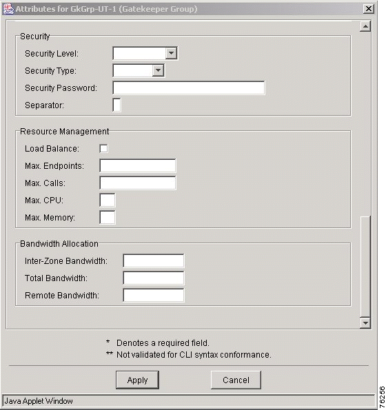
Note See Figure 7-12 for General Attributes, Figure 7-13 for Enhanced Functionality and LRQ/ARQ Handling, and Figure 7-14 for Security, Resource Management, and Bandwidth Allocation. |
Step 4 Enter the gatekeeper group values in the fields.
Step 5 Click Apply to add a new gatekeeper group or click Cancel to cancel the procedure.
|
Note You must be in the Design View to delete a gatekeeper group. |
To delete a gatekeeper group from the dial plan, follow these steps:
Step 1 Expand the AD to view all elements.
Step 2 Right-click the gatekeeper group that you want to delete.
Step 3 Choose the Delete option from the menu. A confirmation dialog box appears.
Step 4 Click Disable, Do Not Disable, or Cancel.
A zone circuit is a zone foreign to VRC that is referred to in a "zone circuit-id" command on a gatekeeper or directory gatekeeper. A zone circuit assigns a trunk carrier (circuit-id) to a gateway.
You can add a zone circuit to a gatekeeper group (GKGrp) or directory gatekeeper group (DGKGrp).
|
Note You can only add a zone circuit to a gatekeeper group or directory gatekeeper group if the CSR route type of the AD is set to trunk-label or carrier and the VRC feature set of the gatekeeper group is dp1.1. |
To add a zone circuit, follow these steps:
Step 1 Expand the AD to view all elements.
Step 2 Click the gatekeeper group or directory gatekeeper group that you want to add a zone to. The Gatekeeper Group window appears.
Step 3 Right-click and select Add from the menu.
Step 4 The Add Zone Circuit window appears (Figure 7-15).
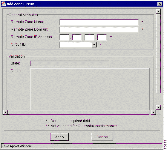
Step 5 Enter the values in the entry fields.
Table 7-9 describes the attributes in the Add Zone Circuit window.
| Attributes | Description |
|---|---|
Remote Zone Name | Name of the remote zone. |
Remote Zone Domain | Domain name of the remote zone. The maximum value is 255 characters. |
Remote Zone IP Address | IP address of the remote zone. |
Circuit ID | The trunk carrier ID associated with this remote zone. |
Step 6 Click Apply to add the zone circuit or click Cancel to cancel the procedure.
This section describes the following topics:
A gatekeeper (GK) is an H.323 component on a LAN that:
Gatekeepers perform the following tasks:
The VRC network supports primary, alternate, overlap, and clustered gatekeepers.
You can view the general attributes of a selected gatekeeper from the following:
|
Note Only the gatekeeper type can be modified. |
Table 7-10 describes the attributes of a gatekeeper.
| General Attributes | Description |
|---|---|
Name | The VRC server contacts the host server to get the host name during discovery or distribution. The maximum value is 64 characters. |
IP Address | The IP address of the element. |
Standby IP | The IP address the gatekeeper uses to communicate with the gatekeeper group if the gatekeeper group is configured for HSRP. |
IOS Version | The Cisco IOS version running on this gatekeeper. |
Feature Set | The VRC feature set supported by this gatekeeper. This field is populated by VRC when the gatekeeper is added to the dial plan. |
Type | The type of gatekeeper. Choose from secondary, cluster, overlap, or backup. The default is primary. There can be only one primary gatekeeper in a gatekeeper group. If you choose:
|
Server Flow High | This read-only field is populated by VRC during the Discovery operation. |
Server Flow Low | This read-only field is populated by VRC during the Discovery operation. |
Max. Queue Length | This read-only field is populated by VRC during the Discovery operation. |
Status | Indicates whether the Cisco VRC server can contact the elements during the Validation process.
|
Details | An optional text string that gives more details about the status of the element. The maximum value is 255 characters. |
This section describes how to add a gatekeeper to a gatekeeper group in the dial plan.
|
Note When you add an element to the dial plan, any preexisting dial plan configuration for that element is overwritten when you commit the design. |
To add a gatekeeper to the topology, see Adding an Element.
|
Note You must be in the Design View to add a gatekeeper to a gatekeeper group in the dial plan. |
To add a gatekeeper to a gatekeeper group in the dial plan, follow these steps:
Step 1 Expand the AD to view all elements.
Step 2 Locate the gatekeeper group that you want to add the gatekeeper to.
Step 3 Right-click the selected gatekeeper group.
Step 4 Choose the Add option and Gatekeeper from the menu. The Add Gatekeeper to Dial Plan window appears.
This window lists available gatekeepers.
Step 5 Select a gatekeeper and click the Add button. A confirmation dialog box appears.
Step 6 Click Apply to apply the values and add a gatekeeper or click Cancel to cancel the procedure.
To edit the attributes of the new gatekeeper, click the Edit Attributes button.
This section describes how to remove a gatekeeper from the dial plan or topology.
|
Note If you are deleting the primary gatekeeper, you must select another primary gatekeeper before you generate a new dial plan. |
|
Note You must be in the Design View to remove a gatekeeper from the dial plan. |
To remove a gatekeeper from the dial plan, follow these steps:
Step 1 Expand the AD to show all elements.
Step 2 Right-click the gatekeeper that you want to remove.
Step 3 Choose Delete from the menu. A confirmation dialog box appears asking you to confirm.
Step 4 Click Disable, Do Not Disable, or Cancel.
|
Note You can only delete an element from the topology if the element is not part of the current baseline or is not being used in a design session. The dial plan state must be Inactive before you can delete it from the topology. |
To delete a gatekeeper from the topology, see Deleting an Element from the Topology.
This section contains the following topics about zones in a dial plan:
A zone is another component of the dial plan that contains address resolution authority (ARA), a set of prefixes that are managed by the zone, and routes that are associated with the zone. Zones partition regions by grouping together gateways with the same routing characteristics.
Zones must contain:
Zone types:
A zone is local or remote in relation to the gatekeeper.
A managed zone is a zone within a managed region and consists of gateways and a set of routes.
The VRC feature set of a managed zone is set by VRC and is determined by the gateway with the lowest VRC feature set. The feature set of the zone is not established until a gateway is added to the zone.
Table 7-11 describes parameters for a managed zone.
| Parameters | Description |
|---|---|
Zone Prefixes | Specify the prefixes supported by the zone. |
Route Scopes | Specify a group of origination and termination points for routes. The route scope groups (for example, voice ports, trunks) makes them available for assignments to routes. |
Zone Subnets | Used to configure a gatekeeper to accept discovery and registration messages sent by endpoints in designated subnets. |
Server Triggers | Used to configure a gatekeeper to connect to a specific back-end server. |
Source Groups | Allow you to create a template for setting the same voice source group parameters on all gateways in a zone. The parameters set in a zone's source group are used when you add a voice source group to the gateway. |
Ingress Route | Defines the pathway from ingress gateways to their ARA. |
Egress Route | Represents the call path from the VoIP network to an egress gateway. |
Translation Profiles | Provide a way to group all ANI and DNIS translation rules together for use on ingress and egress routes. |
Rule Descriptions | Define sets of translation rules for a zone, making them available for assignment to translation profiles. |
Zone Aliases | The name a gatekeeper assigns to a local zone name. |
Hopoff Technology Prefixes | A hopoff zone is the point at which a call transitions from an H.323 to a non-H.323 network. A hopoff technology prefix allows you to specify a technology prefix for a certain zone that you want to use as a hopoff zone. |
Number Expansion | Enables you to define a set of digits for the router to add to the beginning of a dialed string before passing it to the remote telephony device. |
You can view the general attributes of a selected zone from the Design View or the Baseline View:
Table 7-12 describes the attributes of a managed zone.
| General Attributes | Description |
|---|---|
Name | The name of the zone. The maximum value is 64 characters. |
Feature Set | The VRC feature set for this managed zone. The feature set of a managed zone is set by VRC and is determined by the gateway with the lowest feature set. The feature set of the zone is not established until a gateway is added to the zone. |
Protocol | H.323 |
Domain | The domain name of the zone (for example, cisco.com). The maximum value is 255 characters. |
Cost | The cost associated with the zone. The range is 1 to 99. |
Priority | The priority associated with the zone. The range is 1 to 99. |
Status | Indicates whether the Cisco VRC server can contact the elements during the Validation process.
|
Details | Additional information regarding the status of the zone. |
Gatekeeper Group | The gatekeeper group associated with this zone. The gatekeeper group must be in the same managed region as this managed zone. |
| Bandwidth Allocation | |
Inter-zone bandwidth | The maximum aggregate bandwidth for H.323 traffic between one zone and another zone. The range is 1 to 10,000,000. |
Total bandwidth | The maximum aggregate bandwidth for H.323 traffic within a zone and between zones (intrazone and interzone). The range is 1 to 10,000,000. |
|
Note You must be in the Design View to add a managed zone to a region. |
|
Note You must reference a gatekeeper group when you add a managed zone to a managed region. See Adding a New Gatekeeper Group 7-42. |
To add a managed zone to a region, follow these steps:
Step 1 Expand the AD to view all elements.
Step 2 Select a region from the list that you want to add a zone to.
Step 3 Right-click the selected region.
Step 4 Choose Add and Managed Zone from the menu. The Add Managed Zone window appears (Figure 7-16).
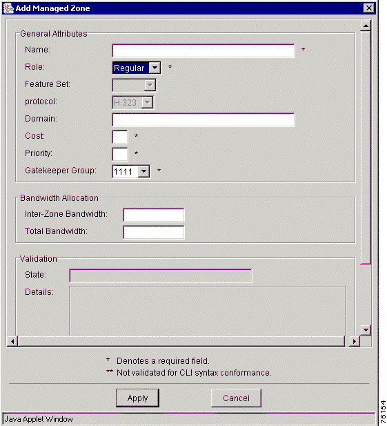
Step 5 Enter values in all fields. See Table 7-12 for a detailed description of each field in the window.
Step 6 Click Apply to add the managed zone to the region or click Cancel to cancel the procedure.
|
Note Before you commit your design, a managed zone must have one zone alias for every gatekeeper in the gatekeeper group. |
Table 7-13 describes the attributes of an unmanaged zone.
| General Attributes | Description |
|---|---|
Name | The name of the zone. The maximum value is 64 characters. |
Domain | The domain name of the zone (for example, cisco.com). The maximum value is 255 characters. |
Cost | The cost associated with the zone. Values range from 1 to 99. |
Priority | The piority associated with the zone. Values range from 1 to 99. |
Foreign Domain | A read-only field that indicates whether this is a foreign domain. |
To add an unmanaged zone to a foreign region, follow these steps:
Step 1 Expand the AD to view all elements.
Step 2 Locate the foreign region you want to add a unmanaged zone to.
Step 3 Right-click the foreign region.
Step 4 Choose Add and Unmanaged Zone from the menus. The Add Unmanaged Zone window appears.
Step 5 Enter the unmanaged zone attribute information (see Table 7-13).
Step 6 Click Apply to add the unmanaged zone to the foreign region or click Cancel to cancel the procedure.
To delete a zone from the dial plan, follow these steps:
Step 1 Expand the AD to show all elements.
Step 2 Right-click the zone that you want to remove.
Step 3 Choose the Delete option. A confirmation dialog box appears asking you to confirm.
|
Note When you delete a managed zone, any remaining references to the zone might prevent a successful commit of the dial plan design. To locate residual references to the deleted zone, manually validate the design. |
Step 4 Click OK to remove the zone or click Cancel to cancel the procedure.
This section describes how to modify local zone names.
During the Discovery operation, VRC preserves the local zone names used when you generate a dial plan for:
|
Note You must be in the Design View to modify local zone names for gatekeepers and directory gatekeepers. |
To modify a local zone name for a gatekeeper, follow these steps:
Step 1 Expand the AD to view all elements.
Step 2 Locate the managed zone associated with a gatekeeper that contains the local zone name that you must change.
Step 3 Create a zone alias for the managed zone. The new local zone name (or zone alias) is applied to the gatekeepers.
|
Note During the Distribution and Commit operations, VRC configures associated gateways to use the zone alias. |
|
Note The local zone name is an attribute for a directory gatekeeper. |
To modify the local zone name for a directory gatekeeper, continue with these steps:
Step 1 Open a design session.
Step 2 Expand the AD to view all elements.
Step 3 Locate and select the directory gatekeeper that you want to modify the local zone name for.
Step 4 Click the Attributes tab.
Step 5 Click Edit Attributes.
Step 6 Modify the Local Zone Name field.
Step 7 Click Apply. The new local zone name (or zone alias) is applied to the directory gatekeeper.
Use the gateway priority option to define how the gatekeeper selects gateways in its local zone for calls to numbers beginning with the associated e164-prefix.
|
Note Do not use this option to set priority levels for a prefix assigned to a remote gatekeeper. |
|
Note You must be in the Design View to add a gateway priority for a zone prefix. |
To assign a priority value for a zone prefix on a gateway, follow these steps:
Step 1 Expand the AD to view all elements.
Step 2 Locate the zone which contains the zone prefix you want to set a priority for.
Step 3 Click the Zone Prefixes tab.
Step 4 Double-click the selected zone prefix.
Step 5 Click the Gateway Priorities tab.
Step 6 Right-click and choose Add from the menu. Select the gateway you want to set a priority for. You can repeat this procedure to assign a zone prefix priority for multiple gateways.
Step 7 Enter the priority value. The range is 1 to 10. The default is 5.
Step 8 Click Apply to assign the zone prefix priority to the gateway or click Cancel to cancel the procedure.
This section describes the zone parameters that you must configure for your dial plan.
Zone prefixes are set up for a:
|
Note You must be in the Design View to add a zone prefix to a zone. |
To add a zone prefix to a zone, follow these steps:
Step 1 Expand the AD to view all elements.
Step 2 Select a zone to add a zone prefix to.
Step 3 Click the Zone Prefixes tab.
Step 4 Right-click and choose Add from the menu.
Step 5 The Add Zone Prefix window appears (Figure 7-17).
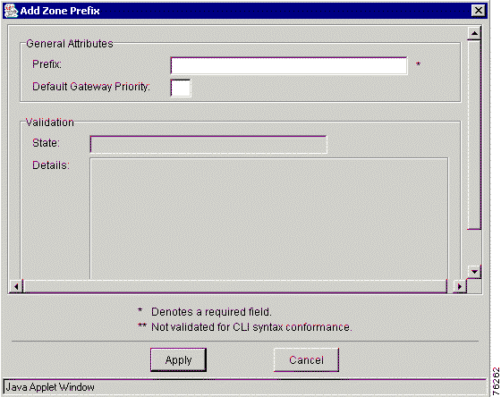
Step 6 Enter the prefix value. This value is the zone prefix to support. The prefix field may be a string of up to 64 characters containing only digits, the asterisk (*) , or a period (.).
Step 7 Enter the default gateway priority. This value is the priority for this prefix in the managed zone. The range is 1 to 10. This cannot be set for an unmanaged zone.
|
Note If the zone prefix is for a managed zone, it must be unique. Zone prefixes for a managed zone in the same gatekeeper group cannot be duplicated. |
Step 8 Click Apply to add a zone prefix or click Cancel to cancel the procedure.
This section describes how to delete a zone prefix from a zone.
|
Note You must be in the Design View to delete a zone prefix. |
|
Note When you delete a zone prefix, any remaining references to the zone prefix might prevent a successful commit of the dial plan design. To locate residual references to the deleted zone prefix, manually validate the design. |
To delete a zone prefix, follow these steps:
Step 1 Expand the AD to view all elements.
Step 2 Select a zone.
Step 3 Right-click and choose Delete from the menu. The Delete Zone Prefix dialog box appears.
Step 4 Click OK to delete the zone prefix or click Cancel to cancel the procedure.
This section describes how to add a zone subnet to a gatekeeper and delete a zone subnet from a gatekeeper. Zone subnets are used to configure a gatekeeper to accept discovery and registration messages sent by endpoints in designated subnets.
|
Note You must be in the Design View to add a zone subnet. |
To add a zone subnet, follow these steps:
Step 1 Expand the AD to view all elements.
Step 2 Select a zone to add a zone subnet to.
Step 3 Click the Zone Subnets tab.
Step 4 Click the Add Zone Subnet tab. The Add Zone Subnet window appears.
Step 5 Enter the values in the following fields:
Step 6 Click Apply to add a new zone subnet or click Cancel to cancel the procedure.
|
Note You must be in the Design View to delete a zone subnet. |
To delete a zone subnet from the dial plan, follow these steps:
Step 1 Expand the AD to view all elements.
Step 2 Locate the zone which contains the zone subnet that you want to delete.
Step 3 Right-click and choose Delete from the menu. The Delete Confirmation dialog box appears.
Step 4 Click OK to remove the zone subnet or click Cancel to cancel the deletion.
Server triggers allow you to configure your gatekeepers to:
You can also set the triggers in the gatekeeper configuration so that they send only specified messages. Servers can also dynamically register their triggers with a gatekeeper.
|
Note Server triggers use the Gatekeeper Transaction Message Protocol (GKTMP) to communicate with servers other than Cisco IOS servers. |
|
Note You must be in the Design View to add a server trigger. |
To add server triggers to a zone, follow these steps:
Step 1 Expand the AD to view all elements.
Step 2 Locate a zone or directory gatekeeper group that you want to add a server trigger to.
Step 3 Click the Server Triggers tab.
Step 4 Click Add Server Trigger. The Add Server Trigger window appears.
Step 5 Enter your values.
Table 7-14 describes the entry fields in the Server Trigger window.
| General Attributes | Description |
|---|---|
Message | Configures triggering on RAS message types. Choose one message type from ARQ, DRQ, LCF, LRJ, LRQ, RAI, RRQ, URQ, or IRR. You can only choose IRR if one of the following conditions exists:
|
Priority | The priority for each trigger. The range is 1 to 20, with 1 being the highest priority. |
Route Server | The route server associated with the gatekeeper for this server trigger. |
Information Only | Specifies whether this server trigger is for information only. There is no need to wait for acknowledgment. |
Destination Type | Choose from e-mail, e164, or h323-id. You can only set this attribute if the message type is ARQ, LRQ, LCF, IRR, or LRJ. You must also specify destination information. |
Destination | The value must be an address of the type specified by the destination type attribute. |
Redirect Reason | Configure a redirect reason to trigger on if the message type is ARQ, IRR, or LRQ. The range is 0 to 65535. Reserved values are: 0=unknown, 1=call forwarding busy or called DTE busy, 2=call forwarded no reply, 4=call deflection, 9=called DTE out of order, 10=call forwarding by the call DTE, and 15=call forwarding unconditionally. |
Remote Ext. Address | The remote extension address. The value can be any string up to 255 characters. |
Endpoint Type | Choose from gatekeeper, h320-gateway, mcu, other gateway, proxy, terminal, voice-gateway. |
Technology Prefix | The default technology prefix for this server trigger if the message type is RRQ or URQ. |
Step 6 Click Apply to add a new server trigger or click Cancel to cancel the procedure.
This section describes how to delete a server trigger. Server triggers allow you to configure your gatekeepers to connect to a specific back-end server.
|
Note You must be in the Design View to delete a server trigger. |
To delete server triggers, follow these steps:
Step 1 Expand the AD to view all elements.
Step 2 Locate a zone that contains the server trigger that you want to delete.
Step 3 Click the Server Triggers tab.
Step 4 Select the server trigger that you want to delete.
Step 5 Click Delete Server Trigger.
Step 6 Click OK to remove the server trigger from the dial plan or click Cancel to cancel the procedure.
This section describes routes which are components of a dial plan that represent call paths entering or leaving a zone and route scope which is a group of one or more routes. There are two types of routes:
|
Note When an egress route is configured on Cisco gateways, it is translated into VoIP dial-peers and outbound POTS dial-peers. |
|
Note When VRC configures an ingress route on Cisco gateways, the route is translated into outbound POTS dial-peers and VoIP dial-peers. |
|
Note You must have a route scope defined for the egress and ingress route before you can add it to the dial plan. |
|
Note You must be in the Design View to add an egress route. |
To add an egress route, follow these steps:
Step 1 Expand the AD to view all elements.
Step 2 Select a zone to add an egress route to.
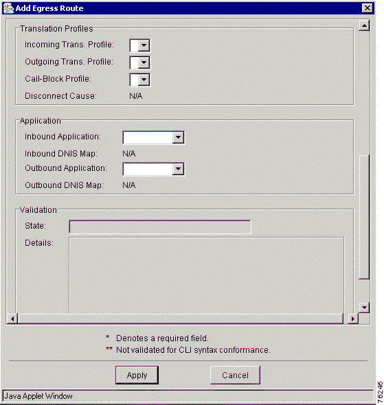
Step 3 Click the Egress Routes tab. The Add Egress Route window appears (Figure 7-18). You must scroll down to view the remaining fields in this window (Figure 7-19).
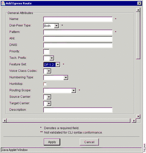
Step 4 Enter values in each field.
Table 7-15 describes the entry fields in the Add Egress Route window.
| General Attributes | Description |
|---|---|
Route ID | Read-only. |
Pattern | The destination pattern, or dialed digit string supported by this route. Legal characters: 0-9 * #, ABDC.[]()%+T. The maximum value is 32 characters. If Tech. Prefix or Target Carrier are not set, then you are required to set this parameter. |
Priority | The priority of this route. The range is 0 to 10. The default is 5. |
Technology Prefix | The technology prefix used for this route. |
Feature Set | The VRC feature set supported by this egress route. Choose from dp1.0 or dp1.1. The default is dp1.0. |
ANI (answer number indication) | The calling number for which this route is applicable. Legal characters: 0-9 * #, ABDC.[]()%+T. The maximum value is 32 characters. |
Voice Class Codec (specifies the voice coder rate of speech for a dial peer) | The Voice Class Codec used by the inbound VoIP dial peer. |
Numbering Type | The numbering type. Choose from international, national, abbreviated, network, reserved, subscriber, and unknown. The default is blank. |
Huntstop | Specifies whether to add a huntstop to the last dial peer in this route. |
Routing Scope | The scope of this egress route. Choose from a managed zone or a route scope. If you choose:
|
DNIS | The dialed number identification service (the called number). Legal characters: 0-9 * #, ABDC.[]()%+T. The maximum value is 32 characters. |
Disconnect Cause | You must set this if a call blocking profile is set. Choose from call-rejected, invalid-number, unassigned-number, or user-busy. |
Source Carrier | Specifies the carrier ID or trunk label for the inbound VoIP dial peer. This parameter can only be set if the VRC feature set is dp1.1 and the CSR route type of the AD is carrier or trunk-label. |
Target Carrier | Specifies the carrier ID or trunk label for the outbound POTS dial peer. This parameter can only be set if the VRC feature set is dp1.1 and the CSR route type is carrier or trunk-label. |
Description | An optional description of this egress route. The maximum value is 64 characters. |
Status (read only) | The validation status of this egress route. |
Details (read only) | Additional information regarding the status of the egress route. |
Translation Profiles | |
Incoming Translation Profile | Associates a translation profile for the incoming side of gateway. If you set this optional parameter, the VRC feature set of this egress route must be dp1.1. If you set this parameter, you must also reference a translation profile with a feature set of dp1.1. |
Outgoing Translation Profile | Associates a translation profile for the outgoing side of the gateway. If you set this optional parameter, the VRC feature set of the translation profile must match the VRC feature set of this egress route. |
Call-Block Profile | Adds a call blocking profile to the inbound dial peer for this route. If you set this optional parameter, the VRC feature set of this egress route must be dp1.1. You must also use a translation profile with a feature set of dp1.1. |
Step 5 Click Apply to add a new egress route or click Cancel to cancel the procedure.
Egress routes represent the call paths from the VoIP network to an egress gateway and are only defined at the zone level.
|
Note You must be in the Design View to delete an egress route. |
To delete an egress route, follow these steps:
Step 1 Expand the AD to view all elements.
Step 2 Select a zone that you want to remove the egress route from.
Step 3 Click the Egress Routes tab.
Step 4 Select the egress route that you want to delete.
Step 5 Click Delete Egress Route.
Step 6 Click OK to remove the egress route from the dial plan or click Cancel to cancel the procedure.
You must have a route scope defined for this route before you can add it to the dial plan.
|
Note You must be in the Design View to add an ingress route to the dial plan. |
To add an ingress route, follow these steps:
Step 1 Expand the AD to view all elements.
Step 2 Select a zone to add an ingress route to.
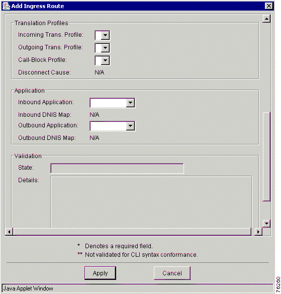
Step 3 Click the Ingress Routes tab. The Add Ingress Route window appears (Figure 7-20). You must scroll down to view the other fields in this window (Figure 7-21).
Step 4 Enter values in the entry fields.
Table 7-16 describes the entry fields in the Add Ingress Route window.
| General Attributes | Description |
|---|---|
Route ID | Read-only. |
Pattern | The destination pattern, or dialed digit string supported by this route. Legal characters: 0-9 * #, ABDC.[]()%+T. The maximum value is 32 characters. Tip: If you end the destination pattern with the * symbol, this indicates a variable length string. For example, 3657* means that the pattern starts with 3657 and may or may not have more characters. |
Priority | The priority of this route. The default is 5. The range is 1 to 10. |
Technology Prefix | The technology prefix used for this route. |
Feature Set | The VRC feature set supported by this ingress route. Choose from dp1.0 or dp1.1. The default is dp1.0. |
ANI | The calling number for which this route is applicable. Legal characters: 0-9 * #, ABDC.[]()%+T. The maximum value is 32 characters. |
Voice Class Codec | The Voice Class Codec used by the outbound VoIP dial peer. A dial peer is an addressable VoIP call endpoint. |
Numbering Type | The numbering type. Choose from international, national, abbreviated, network, reserved, subscriber, and unknown. The default is blank. |
Huntstop | Specifies whether to add a huntstop to the last dial peer in this route. |
ARA Type | The address resolution authority to use for this route. Choose from one of the following:
|
Routing Scope | The scope of this ingress route. Choose from a managed zone or a route scope. If you choose:
|
DNIS | The dialed number identification service (the called number). Legal characters: 0-9 * #, ABDC.[]()%+T. The maximum value is 32 characters. |
Disconnect Cause | You must set this if a call blocking profile is set. |
Source Carrier | Specifies the carrier ID or trunk label for the inbound VoIP dial peer. This parameter can only be set if the VRC feature set is dp1.1 and the CSR route type is carrier or trunk-label. |
Description | An optional description of this egress route. The maximum value is 64 characters. |
Status (read only) | The validation status of this ingress route. |
Details (read only) | Additional information regarding the status of the ingress route. |
Translation Profiles | |
Incoming Translation Profile | Associates a translation profile for the incoming side of gateway. If you set this optional parameter, the VRC feature set of this egress route must be dp1.1. If you set this parameter, you must also reference a translation profile with a feature set of dp1.1. |
Outgoing Translation Profile | Associates a translation profile for the outgoing side of the gateway. If you set this optional parameter, the VRC feature set of the translation profile must match the VRC feature set of this ingress route. |
Call-Block Profile | Adds a call blocking profile to the inbound dial peer for this route. If you set this optional parameter, the VRC feature set of this ingress route must be dp1.1. You must also use a translation profile with a feature set of dp1.1. |
Step 5 Click Apply to a add a new ingress route or click Cancel to cancel the procedure.
Ingress routes define the pathway from ingress gateways to their ARA and you define the ingress routes at the zone level. If you define the ingress route at the zone level, then all gateway groups within the zone share the ingress route.
|
Note You must be in the Design View to delete ingress routes. |
To delete an ingress route, follow these steps:
Step 1 Expand the AD to view all elements.
Step 2 Select a zone.
Step 3 Click the Ingress Routes tab.
Step 4 Select the ingress route that you want to delete.
Step 5 Click Delete Ingress Route. A confirm dialog box appears.
Step 6 Click OK to remove the ingress route from the dial plan or click Cancel to cancel the procedure.
For example, if a route scope of a gateway is assigned to an ingress route, all voice ports on the gateway will be configured to originate calls for that route. Similarly, if a route scope of type voice port is assigned to an egress route, only that voice port will be configured to terminate the route.
|
Note You must be in the Design View to create a route scope. |
To create a route scope for a zone, follow these steps:
Step 1 Expand the AD to view all elements.
Step 2 Select the zone that you want to create a route scope for.
Step 3 Click the Route Scope tab.
Step 4 Right-click and choose Add from the menu. The Add Route Scope dialog box appears (Figure 7-22).
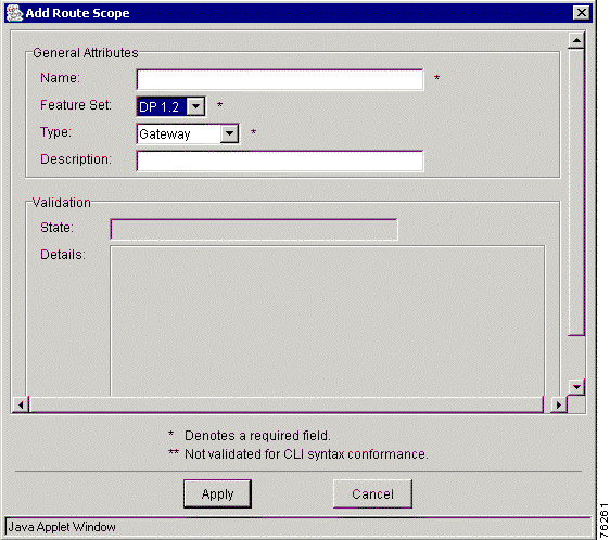
Step 5 Enter values in the entry fields.
Table 7-17 describes the entry fields in the Add Route Scope dialog box.
| General Attributes | Description |
|---|---|
Name | The name of the route scope. The maximum value is 64 characters. |
Feature Set | The VRC feature set supported by this route scope. Choose from dp1.0 or dp1.1. The default is dp1.0. |
Type | Specifies where the routes in this route scope terminate. Choose from Gateway, Voice Port, Trunk Group, or Hunt Group. Trunk Group is not available if the feature set is dp1.0. |
Description | An optional text description of this route scope. The maximum value is 255 characters. |
|
Note A trunk is a logical grouping of POTS interfaces of similar signaling type. This is useful for associating common attributes such as rule descriptions, carrier-id, and so on. |
|
Note During the Discovery operation, VRC might rename your route scope. To change the route scope name back after Discovery, you must manually edit this attribute in the Design View. |
Step 6 Click Apply to create the route scope for the zone or click Cancel to cancel the procedure.
When you delete a route scope, any remaining references to the route scope might prevent a successful commit of the dial plan design. To locate residual references to the deleted route scope, manually validate the design.
|
Note You must be in the Design View to delete a route scope. |
To delete a route scope from the dial plan, follow these steps:
Step 1 Expand the AD to view all elements.
Step 2 Locate the zone which contains the route scope that you want to delete.
Step 3 Click the Route Scope tab.
Step 4 Select the route scope that you want to delete.
Step 5 Right-click and select Delete from the menu. The Confirm dialog box appears.
Step 6 Click OK to confirm the delete or click Cancel to cancel this procedure.
This section describes how to add and delete rule descriptions.
Rule descriptions define sets of translation rules for a zone. The rules provide a mechanism to perform digit manipulation.
|
Note You must be in the Design View to add a rule description. |
To add a rule description, follow these steps:
Step 1 Expand the AD to view all elements.
Step 2 Select a zone to add a rule description to.
Step 3 Click the Rule Descriptions tab.
Step 4 Click Add Rule Description.
Step 5 Enter a number in the Tag field.
Step 6 Choose the appropriate Feature Set for this rule description from the drop-down menu.
Step 7 Click Apply to add a new rule description or click Cancel to cancel the procedure.
|
Note When you delete a rule description, any remaining references to the rule description might prevent a successful commit of the dial plan design. To locate residual references to the deleted rule description, manually validate the design. |
To delete a rule description, follow these steps:
Step 1 Expand the AD to view all elements.
Step 2 Select a zone.
Step 3 Click the Rule Descriptions tab and select the rule description that you want to delete.
Step 4 Click Delete Rule Description. The delete confirmation dialog box appears.
Step 5 Click OK to remove the rule description from the dial plan or click Cancel to cancel the deletion.
|
Note You must be in the Design View to add a translation rule. |
To add a translation rule, follow these steps:
Step 1 Expand the AD to view all elements.
Step 2 Select the zone which contains the rule description that you want to add a translation rule to.
Step 3 Click the Rule Descriptions tab. The list of rule descriptions for this zone is displayed.
Step 4 Double-click the rule description that you want to add a translation rule to.
Step 5 Right-click and choose Add from the menu.
Step 6 Enter the rule description attribute values in the entry fields.
Table 7-18 describes the entry fields in the Add Rule window.
| General Attributes | Description |
|---|---|
Number | The number assigned to this translation rule. The range is:
|
Reject | This optional parameter can only be set if the parent translation rule has a feature set of dp1.1. |
Search Pattern | The maximum value is 32 characters. |
Replacement Pattern | This parameter is required if the Reject parameter is not set. The maximum value is 32 characters. |
Match Type | The match type for this translation rule. Choose from any, international, national, abbreviated, network, reserved, subscriber, and unknown. You must also set a replacement type. |
Replacement Type | The replacement type for this translation rule. Choose from international, national, abbreviated, network, reserved, subscriber, and unknown. This parameter must be set if the Match Type parameter is set and the Reject parameter is not set. |
Match Plan | Specifies the match plan for the Match Type parameter. Choose from any, data, ermes, isdn, national, private, reserved, telex, and unknown. This parameter can only be set if the parent rule description has a feature set of dp1.1. |
Replace Plan | Specifies the match plan for the Match Type parameter. This parameter must be set if the Match Type parameter is set and the Reject parameter is not set. Choose from data, ermes, isdn, national, private, reserved, telex, and unknown. This parameter can only be set if the parent rule description has a feature set of dp1.1. |
Step 7 Click Apply to add this translation rule to the rule description or click Cancel to cancel the procedure.
Translation profiles provide a way to group ANI and DNIS translation rules together to use on ingress or egress routes.
You must have your rule descriptions set up before you can add them to a translation profile.
|
Note You must be in the Design View to add a translation profile. |
To add a translation profile to a dial plan, follow these steps:
Step 1 Expand the AD to view all elements.
Step 2 Select a zone that you want to add a translation profile to.
Step 3 Click the Translation Profiles tab.
Step 4 Right-click and choose Add from the menu. The Add Translation Profile dialog box appears (Figure 7-23).
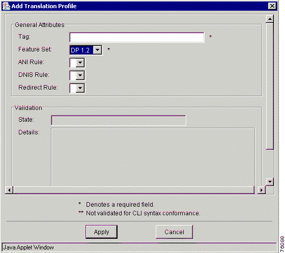
Step 5 Enter the values in the entry fields.
Table 7-19 describes the fields in the Add Translation Profile dialog box.
| General Attributes | Description |
|---|---|
Tag | A unique ID for this rule description. The maximum value is 31 characters. |
Feature Set | The VRC feature set for this translation profile. Choose from dp1.0 or dp1.1. The default is dp1.0. |
ANI Rule | The ID of the rule description meant for ANI. Choose from the available ANI rules in the drop-down list. You must reference a rule description with the same feature set as this translation profile. |
DNIS Rule | The ID of the rule description meant for DNIS. You must reference a rule description with the same feature set as this translation profile. |
Redirect Rule | You can set this optional parameter if the feature set of this translation profile is dp1.1. You must reference a rule description with a feature set of dp1.1. |
Step 6 Click Apply to add a new translation profile or click Cancel to cancel the procedure.
|
Note When you delete a translation profile, any remaining references to the translation profile might prevent a successful commit of the dial plan design. To locate residual references to the deleted translation profile, manually validate the design. |
|
Note You must be in the Design View to delete a translation profile. |
To delete a translation profile from a dial plan, follow these steps:
Step 1 Expand the AD to view all elements.
Step 2 Locate the zone that you want to remove the translation profile from.
Step 3 Click the Translation Profiles tab.
Step 4 Select the translation profile that you want to delete.
Step 5 Click the Delete Translation Profile button.
Step 6 Click OK to remove the translation profile or click Cancel to cancel the procedure.
In most corporate environments, the telephone network is configured so that you can reach a destination by dialing only a portion of the full telephone number. You can define an extension number as the destination pattern for a dial peer.
Adding a number expansion set enables you to define a set of digits for the router to add to the beginning of a dialed string before passing it to the remote telephony device. This reduces the number of digits that a user must dial to reach a remote location.
|
Note You must be in the Design View to add a number expansion set. |
To add a number expansion set, follow these steps:
Step 1 Expand the AD to view all elements.
Step 2 Select a zone to add a number expansion set to.
Step 3 Click the Number Expansion Sets tab.
Step 4 Click the Add Number Expansion Set button. The Add Number Expansion Set dialog box appears.
Step 5 Enter the name of a number expansion set. The maximum value is 64 characters.
|
Note You must specify number expansion rules for all number expansion sets added to the dial plan. |
Step 6 Click Apply to add the number expansion set or click Cancel to cancel the procedure.
|
Note You must be in the Design View to delete a number expansion set. |
To delete a number expansion set from a zone, follow these steps:
Step 1 Expand the AD to view all elements.
Step 2 Locate the zone which contains the number expansion set you want to delete.
Step 3 Click the Number Expansion Sets tab.
Step 4 Click Delete Number Expansion Set to delete the number expansion set from the dial plan or click Cancel to cancel the procedure.
|
Note You must be in the Design View to add a number expansion rule. |
To add a number expansion rule for a number expansion set, follow these steps:
Step 1 Expand the AD to view all elements.
Step 2 Locate the zone which contains the number expansion set you want to add a number expansion rule for.
Step 3 Click the Number Expansion Sets tab. The list of number expansion sets for this zone is displayed.
Step 4 Double-click the number expansion set you want to add a number expansion rule to.
Step 5 Click the Rules tab.
Step 6 Click Add Rule.
Enter the number expansion rule attribute information.
Step 7 Click Apply to add the number expansion rule or click Cancel to cancel the procedure.
|
Note When you delete a number expansion rule, any remaining references to the number expansion rule might prevent a successful commit of the dial plan design. To locate residual references to the deleted number expansion rule, manually validate the design.. |
To delete a number expansion rule, follow these steps:
Step 1 Expand the AD to view all elements.
Step 2 Select the zone which contains the number expansion set you want to delete the number expansion rule from.
Step 3 Click the Number Expansion Sets tab. The list of number expansion sets for this zone is displayed.
Step 4 Double-click the number expansion set which contains the number expansion rule you want to delete.
Step 5 Click the Rules tab. Select the number expansion rule you want to delete.
Step 6 Click Delete Rule to remove the number expansion rule from the dial plan or click Cancel to cancel the procedure.
A zone alias is the name a gatekeeper assigns to a local zone name. VRC creates a zone alias during the Discovery operation or you can enter a zone alias manually.
When a gateway registers with a gatekeeper, it uses the zone alias name. A managed zone must have one zone alias for every gatekeeper in the gatekeeper group.
|
Note You must be in the Design View to add zone aliases. |
To manually add a zone alias for a zone, follow these steps:
Step 1 Expand the AD to view all elements.
Step 2 Locate the zone that you want to create a zone alias for.
Step 3 Click the Zone Aliases tab.
Step 4 Right-click and choose Add from the menu. The Add Zone Alias dialog box appears (Figure 7-24).
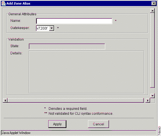
Step 5 Enter the following values in the entry fields:
Step 6 Click Apply to create the zone alias or click Cancel to cancel the procedure.
A source group is a template for setting individual voice source groups. A source group allows you to set the same parameters for all gateways in a zone. The parameters set in a zone's source group are used when you add a voice source group to the gateway.
To apply these parameters to a particular gateway in a zone, see Adding a Voice Source Group.
|
Note You must be in the Design View to add a source group for a zone. |
To create a source group for a zone, follow these steps:
Step 1 Expand the AD to view all elements.
Step 2 Locate the zone that you want to add a source group to.
Step 3 Click the Source Group tab.
Step 4 Right-click and select Add from the menu. The Add Source Group dialog box appears (Figure 7-25).
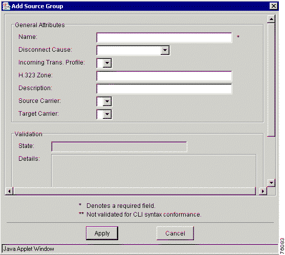
Step 5 Enter the values in the entry fields.
Table 7-20 describes the entry fields in the Add Source Group dialog box.
| General Attributes | Description |
|---|---|
Name | The name of the source group. The maximum value is 31 characters. |
Disconnect Cause | Reason for disconnecting. Choose from call-rejected, invalid-number, unassigned-number, user-busy. |
Incoming Translation Profile | Associates a translation profile for the incoming side of the gateway. The VRC feature set of the translation profile must be dp1.1. |
H.323 Zone | The maximum value is 127 characters. |
Description | The maximum value is 63 characters. |
Source Carrier | Specifies the inbound VoIP dial peer. Can only be set if the CSR route type of the AD is set to carrier or trunk-label. |
Target Carrier | Specifies the outbound POTS dial peer. Can only be set if the CSR route type of the AD is set to carrier or trunk-label. |
Step 6 Click Apply to add a source group or click Cancel to cancel the procedure.
|
Note You must be in the Design View to delete a source group from a zone. |
To delete a source group from a zone, follow these steps:
Step 1 Expand the AD to view all elements.
Step 2 Locate the zone that you want to delete the source group from.
Step 3 Click the Source Group tab.
Step 4 Select the source group that you want to delete.
Step 5 Right-click and select Delete from the menu.
Step 6 Click OK to delete a source group from a dial plan or click Cancel to cancel the procedure.
A hopoff zone is the point at which a call transitions from H.323 to a non-H.323 network. A hopoff technology prefix allows you to specify a technology prefix for a certain zone that you want to use as a hopoff zone. You can specify a hopoff technology prefix for a managed zone or an unmanaged zone.
|
Note You must already have a technology prefix added to the dial plan before you can specify it for a hopoff zone and you must be in the Design View. |
To add a hopoff technology prefix to a zone, follow these steps:
Step 1 Expand the AD to view all elements.
Step 2 Select a zone to add a hopoff technology prefix to.
Step 3 Click the Hopoff Tech Prefixes tab.
Step 4 Right-click and choose Add from the menu. The Add Hopoff Tech Prefix dialog box appears (Figure 7-26).
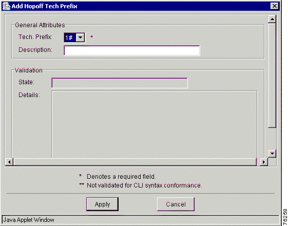
Step 5 Enter the following values:
|
Note If you are specifying a hopoff technology prefix for a managed zone, then the managed zone must contain at least one egress route that references this same technology prefix. |
|
Note A zone can have multiple hopoff technology prefixes. |
Step 6 Click Apply to add the hopoff technology prefix or click Cancel to cancel the procedure.
This section contains the following topics about gateways:
A gateway is the point at which a circuit-switched fax or voice call is encoded (using a codec) and repackaged into IP packets, or vice versa. A gateway initiates a call setup with an H.323 gatekeeper through H.225 RAS. The originating gateway terminates the VoIP call to an appropriate destination gateway with the gatekeeper's assistance.
You can perform the following tasks when using VRC:
The VRC network supports the following Cisco platforms as H.323 gateways:
You can view the general attributes of a selected gateway in the following views:
Table 7-21 describes the attributes of a gateway.
| General Attributes | Description |
|---|---|
Name | The gateway name. This corresponds to the name part of the full DNS host name. |
H.323 ID | The H.323-ID for the gateway. This is usually the fully qualified e-mail ID, with the domain name being the same as this gateway's gatekeeper. |
IP Address | The IP address of the gateway. This read-only field is populated by the VRC client. |
Feature Set | The VRC feature set supported by this gateway. This field is populated by VRC when the gateway is added to the dial plan. |
IOS Version | The Cisco IOS version running on this gateway. |
Incoming VoIP Trans. Profile | Associates a translation profile for the incoming side of gateway. The translation profile must reside in the same managed zone as the gateway. The VRC feature set of the translation profile must match the feature set of the gateway. |
Number Expansion Set | The number expansion set for this gateway. |
OSP Enabled | Specifies if this gateway responds to OSP servers. |
Circuit | Assigns a trunk label or carrier ID (circuit-ID) to a gateway. You can only set this parameter if the gateway's VRC feature set is dp1.1, the managed zone's gatekeeper group is set to a gatekeeper group with a VRC feature set of dp1.1 and a CSR route type of carrier or trunk-label. |
Max. Calls | Specifies the maximum number of voice or data calls allowed on the trunk group. You can only set this parameter if the circuit parameter is set. The range is 1 to 10000. |
Needs Reactivation | This is a read-only field and indicates whether you need to reactivate the gateway because the configuration has been changed. The default is Yes. You cannot commit a dial plan design if one or more gateways have this attribute set to Yes. |
| RTCP | |
Timer Receive RTCP | Enables the Real-Time Control Protocol (RTCP) timer and configures a multiplication factor for the RTCP timer interval. The range is 2 to 1000. This parameter can only be set if the VCR feature set for this gateway is dp1.1. |
IP RTCP Report Interval | Configures the average reporting interval between subsequent RTCP report transmission. The range is 1 to 65535. This parameter can only be set if the VCR feature set for this gateway is dp1.1. |
Status | Indicates whether the Cisco VRC server can contact the elements during the Validation process.
|
Details | An optional text string that gives more details about the status of the element. The maximum value is 255 characters. |
| Security | |
Access Token | A password for registration. The maximum value is 20 characters. The default is blank. |
Security Level | The security level of the gateway. You must set a security level if the access token is set. Choose from endpoint, per-call, or all. |
| Resource Management | |
Resource Threshold All | Applies the high and low parameter settings to all monitored H.323 resources. This parameter can only be set if Resource Threshold High and Resource Threshold Low are set. |
Resource Threshold High | A resource utilization level that triggers an RAI message that indicates that H.323 resource usage is high. The range is 1 to 100. The default is blank. |
Resource Threshold Low | A resource utilization level that triggers an RAI message that indicates that H.323 resource usage has dropped below the high usage level. The range is 1 to 100. The default is blank. |
Emulate H.323 Bandwidth | If checked, allows the gateway to terminate calls using H.323 bidirectional bandwidth. This parameter can only be set if the VCR feature set for this gateway is dp1.1. |
A gateway must be defined in the topology before you can add it to the dial plan.
|
Note To add a gateway to the topology, see Adding an Element. |
|
Note You must be in the Design View to add a gateway to the dial plan. |
To add a gateway to the dial plan, follow these steps:
Step 1 Expand the AD to view all elements.
Step 2 Locate the managed zone you want to add a gateway to.
Step 3 Right-click the selected zone and choose Add to Dial Plan and Gateway from the menu. The Add Gateway to Dial Plan window appears. This window lists the IP addresses of available gateways.
Step 4 Select the gateway and click the Add button. An information dialog box appears, asking you to confirm.
Step 5 If you choose OK, the gateway is added to the dial plan.
Step 6 If you choose Cancel, the gateway is not added and you are returned to the Add Gateway to Dial plan window.
Step 7 To edit the attributes of the new gateway, select the new gateway and then click the Edit Attributes button.
To delete a gateway from the:
You can identify and list the set of gateways which might terminate a given dial string. For more information, see Finding Terminating Gateways.
The call path verification feature in VRC is used to trace a call in a Voice-over-IP (VoIP) H.323 network. The call is traced from the originating gateway, through all gatekeepers used to resolve the destination address, and finally to the terminating gateway.
|
Note Routes identified with target ipv4.* or dns.* are reported but not traced or verified by VRC. |
To trace the call path using VRC, you must enter the following information:
|
Note The target carrier setting is optional. If you leave this field blank, you test the behavior of the system with the routing server down or not used. |
|
Note VRC call path verification does not recognize voice source groups, their translation rules, or ingress route call blocking. |
|
Note VRC does not validate non-dial plan parameters such as codec or DTMF-relay between the call endpoints. |
Use call path verification to trace the full route of a call from gateway to gateway.
|
Note You can verify a call path from the Baseline View or the Design View. |
You must find the terminating gateways before you verify a call path.
|
Note If you trace a call path from a voice port or trunk group, select a voice port or trunk group that has a translation profile defined so that the translation rules can be applied to the called number. If there are no translation rules defined and you are using carrier-based routing, trace the call path from the trunk group. |
To verify a call path, follow these steps:
Step 1 Expand the AD to view all elements.
Step 2 Locate the gateway that you want to trace a call path from. You can also trace a call path from a voice port or trunk group on a gateway.
Step 3 Right-click the gateway (voice port or trunk group) and choose Verify Call Path from the menu.
The Verify Call Path dialog box appears (Figure 7-27).
Step 4 Enter the incoming dialed string that you want to find the call path for. Use only digits in your dial string, leaving out dashes and dots. You can enter only a prefix for your string.
Step 5 If the CSR route type for the AD is set to carrier or trunk-label, select a target carrier. If you leave the target carrier field blank, the call path is verified regardless of the routing server's status.
Step 6 Click OK to display the call paths from the incoming dial string or click Cancel to cancel the procedure.
This section describes the following parameters that are required to configure gateways in your dial plan:
Figure 7-28 and Figure 7-29 display the attributes available to a gateway.
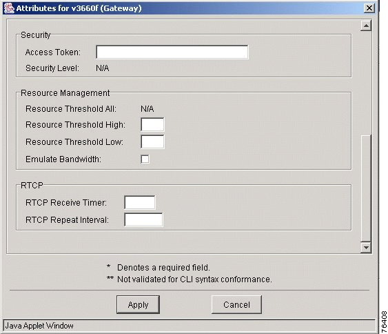
When you execute the Discovery operation for a gateway, the Ethernet port associated with the IP address specified in the topology for a gateway is identified. The baseline dial plan shows this Ethernet port for each gateway.
Use the command line interface to add or delete an Ethernet port from the gateway.
View the Ethernet ports that are assigned to a gateway in the Design View or the Baseline View. Use this procedure to assign an Ethernet port on a gateway using the VRC client.
|
Note You must first create the Ethernet port using the command line interface (CLI). |
|
Note You must be in the Design View to assign an Ethernet port. |
To assign an Ethernet port on a gateway, follow these steps:
Step 1 Expand the AD to view all elements.
Step 2 Locate the gateway that you want to assign an Ethernet port to.
Step 3 Click the Ethernet tab.
Step 4 Right-click and choose Add from the menu. The Add Ethernet Port window appears.
Step 5 Enter the name of the Ethernet port that you want to assign to the gateway.
Step 6 Click Apply to add the Ethernet port to the gateway or click Cancel to cancel the procedure.
A trunk group is a logical grouping of multiple DS1 interfaces with the same signaling characteristics that you can provision as an outbound dial peer target. You can perform the following functions:
|
Note You can only use a VRC-discovered trunk group in your dial plan if the associated gateway has a VRC feature set of dp1.1. |
|
Note You must be in the Design View to edit trunk group attributes. |
To edit the attributes for a trunk group on a gateway, follow these steps:
Step 1 Expand the AD to view all elements.
Step 2 Locate the gateway with the trunk group that you want to edit.
Step 3 Select the trunk group.
Step 4 Click the Edit Attributes button. The Edit Trunk Group window appears.
Step 5 Enter the values that you want to change.
Table 7-22 describes the entry fields in the Edit Trunk Group window.
| General Attribute | Description |
|---|---|
Name | The name of the trunk group. A read-only field. |
Hunt Scheme | Specifies the way to select an interface from a trunk group for an outgoing call. Choose from least-idle, least-used, longest-idle, random, round-robin, sequential. |
Hunt Order | Choose from both, even, or odd. Do not set this parameter if Hunt Scheme is set to random. |
Hunt Direction | Choose from up or down. Set this parameter if Hunt Scheme is set to least-used, round-robin, or sequential. |
Incoming Translation Profile | Associates a translation profile for the incoming side of the gateway. The VRC feature set of the translation profile must be dp1.1. |
Outgoing Translation Profile | Associates a translation profile for the outgoing side of the gateway. The feature set of the translation profile must be dp1.1. |
Description | The maximum value is 63 characters. |
Carrier ID | The ID for the carrier that owns this trunk group. You can set this parameter only if the CSR route type is carrier. |
Step 6 Click Apply to apply the values to the trunk group or click Cancel to cancel the procedure.
|
Note In order to use trunk groups in a hunt group, you must first create the trunk group using the CLI. (VRC creates hunt groups but cannot provision trunk groups.) |
To add hunt groups to a gateway, follow these steps:
Step 1 Expand the AD to view all elements.
Step 2 Locate the gateway that you want to add a hunt group to.
Step 3 Click the Hunt Groups tab.
Step 4 Right-click and choose Add from the menu. The Add Hunt Group window appears.
Step 5 Enter the values in the entry fields.
Step 6 Click Apply to add the hunt group or click Cancel to cancel the procedure.
A voice source group allows you to assign a name to a set of source IP group characteristics. The terminating gateway uses these characteristics to identify and translate the incoming VoIP call.
|
Note You must set up a source group before you can add a voice source group. The voice source group receives parameter settings from the parent source group. You can only add a voice source group to a gateway if the VRC feature set of the gateway is dp1.1. |
|
Note You must be in the Design View to add a unique voice source group. |
To add a unique voice source group to a gateway, follow these steps:
Step 1 Expand the AD to view all elements.
Step 2 Locate the gateway that you want to add a voice source group to.
Step 3 Click the Voice Source Group tab.
Step 4 Right-click and choose Add from the menu. The Add Voice Source Group window appears.
Step 5 Enter values in the entry fields.
Step 6 Table 7-23 describes the fields in the Add Voice Source Group window.
| General Attributes | Description |
|---|---|
Name | The name of the voice source group. The maximum value is 31 characters. |
Source Group | The parent source group which contains the parameter settings to use for this voice source group. |
Access List | The access list number for this voice source group to be used for call blocking. You must also set a disconnect cause for call blocking. This parameter allows the voice source group to block calls from the IP address specified in the access list. |
Step 7 Click Apply to add the voice source group to the gateway or click Cancel to cancel the procedure.
A voice port is an interface that connects the gateway to the PSTN network or the customer premise equipment (CPE). You can view the voice ports that are available on a gateway in the Design View or the Baseline View. You can edit voice port attributes using the VRC client; but you must first create the voice port using the command line interface (CLI).
|
Note You must be in the Design View to edit a voice port. |
To edit a voice port, follow these steps:
Step 1 Expand the AD to view all elements.
Step 2 Locate the gateway with the voice port that you want to edit.
Step 3 Select the voice port.
Step 4 Click the Edit Attributes button. The Attributes for Voice Port window appears.
Step 5 Enter values that you want to change.
Step 6 Click Apply to add the translation profiles or click Cancel to cancel the procedure.
When you perform the Discovery operation on a gateway, all IP Standard (1-99) access lists for a gateway become part of the dial plan. VRC only discovers and displays access lists for gateways. VRC does not provision gateways.
The baseline and design dial plan show all access lists associated with a gateway on the gateway's Access Lists tab. The Access Lists tab is highlighted only if VRC discovers access lists provisioned on a gateway.
Use the CLI to add or delete an access list for a gateway.
|
Note You must first create the access list using the command line interface (CLI) before you can manually assign it to the gateway. |
To add a predefined access list to a gateway manually, follow these steps:
Step 1 Expand the AD to view all elements.
Step 2 Locate the gateway that you want to assign an access list to.
Step 3 Click the Access Lists tab.
Step 4 Right-click and choose Add from the menu.
Step 5 Enter the access list number and an optional description.
Step 6 Click Apply to add the access list or click Cancel to cancel the procedure.
![]()
![]()
![]()
![]()
![]()
![]()
![]()
![]()
Posted: Mon Oct 14 09:57:41 PDT 2002
All contents are Copyright © 1992--2002 Cisco Systems, Inc. All rights reserved.
Important Notices and Privacy Statement.