|
|

The Catalyst 1600 supports broadcast filtering and port-to-port blocking, which enables you to block or enable the forwarding of packets between specified ports on a Catalyst 1600, to include or exclude particular rings, by the configuration of logical workgroups, known as virtual LANs.
By defining virtual LANs, you can:
A virtual LAN consists of two or more Token Ring segments that are joined by Catalyst 1600 devices, where stations can only make connections to other stations or servers that are part of the same virtual LAN. The result is that broadcast traffic originating on any ring is only received by stations on rings that belong to the same virtual LAN.
This means that service advertisement, address resolution, and route discovery packets that originate on a ring that does belong to a virtual LAN are not received by stations on rings that do not belong to the same virtual LAN.
For example, you can define several overlapping virtual LANs that share common resources like file servers and print servers.

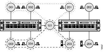
In Figure B-1, the workgroups rings are divided into two virtual LANs which both include the centrally-located server ring 203. The first virtual LAN includes rings 003, 004, 101 and 203, and the second includes rings 203 and 204. Although the virtual LANs share the ring on which the servers are located, broadcast frames are not forwarded from either virtual LAN onto rings that only belong to the other.
If the workgroups move to a new physical location, the administrator can redefine the virtual LAN to ensure that the workgroup can continue to access the ring to which the server is attached.
The Catalyst 1600 supports the definition of permeable and impermeable virtual LANs, which can be configured using TrueView Catalyst 1600 Manager. See Table B-1.
| Type | Description |
|---|---|
| Impermeable | You can define impermeable virtual LANs by specifying an explicit list of the rings that belong to the virtual LAN.
Define impermeable virtual LANs when one or more Catalyst 1600 devices connect a number of Token Rings to form a large LAN. For more information see "Impermeable Virtual LANs" later in this appendix. |
| Permeable | You can define permeable virtual LANs by specifying a list of rings. Permeable virtual LANs do not restrict the forwarding of broadcast traffic to an explicit list of the rings.
Define permeable virtual LANs when Catalyst 1600 devices are installed in a large source routed network, to define logical workgroups without explicitly specifying the rings that belong to each virtual LAN. For more information see "Impermeable Virtual LANs" later in this appendix. |
In an impermeable virtual LAN, forwarding decisions are based on the ring on which the frame originated, which is determined from the Routing Information Field (RIF) in each source routed frame. This means that broadcast traffic is restricted to the explicit list of rings that belong to the virtual LAN.
Impermeable virtual LANs that span multiple Catalyst 1600 devices must include a ring that connects the devices.

In Figure B-2, two impermeable virtual LANs both include a ring that has servers attached. The first virtual LAN includes rings 001, 002, 101, 201 and 203, and the second includes rings 003, 004, 101 and 203. Broadcast frames are restricted to the list of rings that belong to the virtual LAN and are not forwarded from either virtual LAN onto rings that only belong to the other.
Broadcast frames originating on rings 202 and 204 are not forwarded to rings that belong to either virtual LAN and the rings are treated as if they were part of a third, undefined virtual LAN.
In a permeable virtual LAN, any ring that is connected directly to a ring that belongs to the virtual LAN can forward broadcast frames onto the virtual LAN, and to receive broadcast frames from inside the virtual LAN.

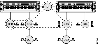
In Figure B-3, a permeable virtual LAN includes rings 101, 003, 004 and 203. However, because the virtual LAN is permeable, rings 001 and 002 can forward broadcast frames onto the virtual LAN, and receive broadcast frames from inside the virtual LAN.
Ring 204 is not directly connected to a ring that is included in the virtual LAN. Therefore, the stations on the ring cannot forward broadcast frames onto the virtual LAN or receive broadcast frames from inside the virtual LAN.
To reduce unnecessary broadcast traffic, you can define the type of stations that are connected to each Catalyst 1600 port.
On IPX and NetBIOS networks, the Catalyst 1600 uses information about the type of station to block broadcast frames originating on workstation-only rings and destined for other workstation-only rings. For example, in Figure B-2 and Figure B-3, broadcast frames originating on ring 003 are not forwarded to ring 004.
The station types are described in Table B-2.
| Station type | Description |
|---|---|
| Workstations | Only workstations are attached to the ring that is connected to the Catalyst 1600 port. |
| Anything | Workstations and servers are attached to the ring that is connected to the Catalyst 1600 port. The servers need to transmit broadcast frames to workstation-only rings. |
The Catalyst 1600 performs port-to-port blocking on all IPX and NetBIOS source-route broadcast frames, except for ADD_NAME_QUERY and ADD_GROUP_NAME_QUERY NetBIOS frames.
For information about configuring the station type for each port, see the section "Viewing and Configuring Source-routing Information" in Chapter 3, "Managing Devices."
The Catalyst 1600 uses information stored in Management Information Base (MIB) files to support the configuration of up to 16 virtual LANs per Catalyst 1600. Each virtual LAN may consist of up to 64 rings.
By default, the Catalyst 1600 forwards all broadcast traffic. For information about configuring virtual LANs using TrueView Catalyst 1600 Manager, see the section "Configuring Virtual LANs" in Chapter 3, "Managing Devices."
 | Warning Do not attempt to configure virtual LANs by manually editing Catalyst 1600 MIBs or the RSVLAN.INI file. Editing files manually may cause unpredictable network behavior. |
|
|