|
|

Cisco Gigabit Ethernet SwitchProbe devices require a single- or multi-mode fiber optic splitter tap to monitor the network. This document provides instructions for connecting the fiber optic splitter tap to a SwitchProbe device.
Cisco Gigabit Ethernet SwitchProbe devices are shipped with a single- or multi-mode fiber optic splitter tap kit, which consists of the following items:
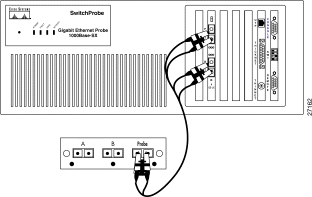
Figure 1 shows the front panel of a fiber optic splitter tap.

Connecting the Gigabit Ethernet interface to a full-duplex network segment is a two-stage process.
To connect a fiber optic splitter tap to the SwitchProbe device, see Figure 2 and follow these steps:
Step 2 Locate the 9.84 foot (3 meter) fiber cable (with two male SC connectors at one end and one male SC connector at the other end) that was included with the tap.
Step 3 Remove all dust caps from the connectors at the ends of the cables.
Step 4 Plug the end of the fiber cable (labeled DCE) into port 1 of the Gigabit Ethernet interface (port 1 is the DCE port).
Step 5 Plug the end of the fiber cable (labeled DTE) into port 2 of the Gigabit Ethernet interface (port 2 is the DTE port).
Step 6 Plug the other end of the fiber cable (the one with a single connector) into the port labeled Probe on the fiber optic splitter tap.

After you connect the Gigabit Ethernet interface on the SwitchProbe device to the tap, you must connect the tap to the network segment.
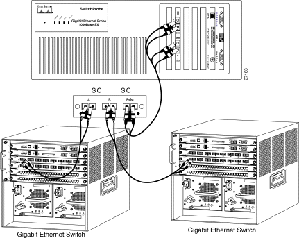
To do so, see Figure 3 and follow these steps:
Step 2 Unplug this cable from one of the two Gigabit Ethernet devices.
Step 3 Plug the end of the cable (that you just unplugged) into the one of the two remaining female SC duplex ports on the tap (either port A or B).
Step 4 Locate an SC-to-SC fiber cable (with one male SC connector at each end).
Step 5 Plug one end of the SC-to-SC fiber cable into the second Gigabit Ethernet switch, server, or router.
Step 6 Plug the other end of the cable into the remaining female SC duplex port on the tap (A or B).
As illustrated in Figure 3, there should now be one cable extending from one Gigabit Ethernet switch, server, or router to the tap A port, and another cable from another Gigabit Ethernet switch, server, or router to the tap B port, and the tap should be connected to the SwitchProbe device.

Cisco Connection Online (CCO) is Cisco Systems' primary, real-time support channel. Maintenance customers and partners can self-register on CCO to obtain additional information and services.
Available 24 hours a day, 7 days a week, CCO provides a wealth of standard and value-added services to Cisco's customers and business partners. CCO services include product information, product documentation, software updates, release notes, technical tips, the Bug Navigator, configuration notes, brochures, descriptions of service offerings, and download access to public and authorized files.
CCO serves a wide variety of users through two interfaces that are updated and enhanced simultaneously: a character-based version and a multimedia version that resides on the World Wide Web (WWW). The character-based CCO supports Zmodem, Kermit, Xmodem, FTP, and Internet e-mail, and it is excellent for quick access to information over lower bandwidths. The WWW version of CCO provides richly formatted documents with photographs, figures, graphics, and video, as well as hyperlinks to related information.
You can access CCO in the following ways:
For a copy of CCO's Frequently Asked Questions (FAQ), contact cco-help@cisco.com. For additional information, contact cco-team@cisco.com.

![]()
![]()
![]()
![]()
![]()
![]()
![]()
![]()
Posted: Thu Jul 25 04:20:49 PDT 2002
All contents are Copyright © 1992--2002 Cisco Systems, Inc. All rights reserved.
Important Notices and Privacy Statement.