|
|

This document describes how to connect a Cisco E-3 ATM SwitchProbe device to an E-3 tap.
The E-3 tap is a passive device that presents high impedance to the link. Therefore, you can connect and disconnect the E-3 ATM SwitchProbe device from the tap without disrupting the integrity of the link being monitored.
The E-3 tap kit consists of the following items.
Figure 1 shows the front panel of the E-3 tap. The front panel contains four
BNC connectors.

Figure 2 shows the rear panel of the E-3 tap. The rear panel contains a female DB-15 connector.
Before connecting this device to the network, note the following warnings.
 |
Note To see the warnings in multiple languages, see the appendix "Translated Safety Warnings" in the Cisco SwitchProbe Installation and Configuration Guide. |
 |
Warning Before opening the chassis, disconnect the telephone-network cables to avoid contact with telephone network voltages. |
 |
Warning Do not work on the system or connect or disconnect cables during periods of lightning activity. |
 |
Warning The equipment is intended to be installed and maintained by service personnel only as defined by AS/NZS 3260 Clause 1.2.14.3 Service Personnel. |
 |
Warning Hazardous network voltages are present in WAN ports regardless of whether power to the unit is OFF or ON. To avoid electric shock, use caution when working near WAN ports. When detaching cables, detach the end away from the unit first. |
Connecting the E-3 ATM SwitchProbe device to a network segment is a two-stage process:
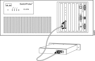
To connect the E-3 tap to the E-3 ATM SwitchProbe device, see Figure 3 and follow these steps:
Step 1 Locate the 15-foot cable (with a male DB-15 connector at one end and a female DB-15 connector at the other end) that is shipped with the tap.
Step 2 Plug the female connector of this cable into port 1 on the E-3 ATM interface
(port 1 is the ATM port).
Step 3 Plug the other end of the 15-foot cable (the end with the male DB-15 connector) into the female DB-15 port of the E-3 tap.

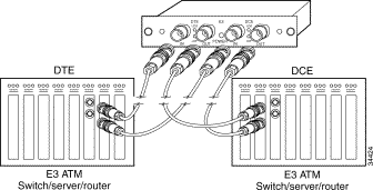
To connect the E-3 tap to the network, see Figure 4 and follow these steps:
Step 1 Locate the two cables that connect one E-3 ATM switch, server, or router to another E-3 ATM switch, server, or router.
Step 2 Unplug these two cables from one of the two E-3 ATM devices.
Step 3 Plug the ends of these two cables into the two ports labeled IN on the E-3 tap.
(The device plugged into the two IN ports is the DTE device).
Step 4 Locate two six-foot cables (with BNC connectors at each end) that are shipped with the SwitchProbe device.
Step 5 Plug one end of each of these cables into the two ports labeled OUT on the
E-3 tap.
Step 6 Plug the remaining connector on each of these cables into the E-3 ATM device from which you unplugged cables in Step 2. (The device plugged into the two OUT ports on the tap is the DCE device.)
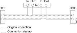
Step 7 See Figure 5 to confirm that the new cabling setup reestablished the connections you had previously.


You can access the most current Cisco documentation on the World Wide Web at http://www.cisco.com, http://www-china.cisco.com, or http://www-europe.cisco.com.
Cisco documentation and additional literature are available in a CD-ROM package, which ships with your product. The Documentation CD-ROM is updated monthly. Therefore, it is probably more current than printed documentation. The CD-ROM package is available as a single unit or as an annual subscription.
Registered CCO users can order the Documentation CD-ROM and other Cisco Product documentation through our online Subscription Services at http://www.cisco.com/cgi-bin/subcat/kaojump.cgi.
Nonregistered CCO users can order documentation through a local account representative by calling Cisco's corporate headquarters (California, USA) at 408 526-4000 or, in North America, call 800 553-NETS (6387).
Cisco provides Cisco Connection Online (CCO) as a starting point for all technical assistance. Warranty or maintenance contract customers can use the Technical Assistance Center. All customers can submit technical feedback on Cisco documentation using the web, e-mail, a self-addressed stamped response card included in many printed docs, or by sending mail to Cisco.
Cisco continues to revolutionize how business is done on the Internet. Cisco Connection Online is the foundation of a suite of interactive, networked services that provides immediate, open access to Cisco information and resources at anytime, from anywhere in the world. This highly integrated Internet application is a powerful, easy-to-use tool for doing business with Cisco.
CCO's broad range of features and services helps customers and partners to streamline business processes and improve productivity. Through CCO, you will find information about Cisco and our networking solutions, services, and programs. In addition, you can resolve technical issues with online support services, download and test software packages, and order Cisco learning materials and merchandise. Valuable online skill assessment, training, and certification programs are also available.
Customers and partners can self-register on CCO to obtain additional personalized information and services. Registered users may order products, check on the status of an order and view benefits specific to their relationships with Cisco.
You can access CCO in the following ways:
You can e-mail questions about using CCO to cco-team@cisco.com.
The Cisco Technical Assistance Center (TAC) is available to warranty or maintenance contract customers who need technical assistance with a Cisco product that is under warranty or covered by a maintenance contract.
To display the TAC web site that includes links to technical support information and software upgrades and for requesting TAC support, use www.cisco.com/techsupport.
To contact by e-mail, use one of the following:
| Language | E-mail Address |
|---|---|
English | tac@cisco.com |
Hanzi (Chinese) | chinese-tac@cisco.com |
Kanji (Japanese) | japan-tac@cisco.com |
Hangul (Korean) | korea-tac@cisco.com |
Spanish | tac@cisco.com |
Thai | thai-tac@cisco.com |
In North America, TAC can be reached at 800 553-2447 or 408 526-7209. For other telephone numbers and TAC e-mail addresses worldwide, consult the following web site: http://www.cisco.com/warp/public/687/Directory/DirTAC.shtml.
If you are reading Cisco product documentation on the World Wide Web, you can submit technical comments electronically. Click Feedback in the toolbar and select Documentation. After you complete the form, click Submit to send it to Cisco.
You can e-mail your comments to bug-doc@cisco.com.
To submit your comments by mail, for your convenience many documents contain a response card behind the front cover. Otherwise, you can mail your comments to the following address:
Cisco Systems, Inc.
Document Resource Connection
170 West Tasman Drive
San Jose, CA 95134-9883
We appreciate and value your comments.
![]()
![]()
![]()
![]()
![]()
![]()
![]()
![]()
Posted: Fri Sep 6 19:58:17 PDT 2002
All contents are Copyright © 1992--2002 Cisco Systems, Inc. All rights reserved.
Important Notices and Privacy Statement.