|
|

Several Cisco WAN SwitchProbe devices—those that connect to the WAN link between a Cisco router with an integrated CSU/DSU and the WAN demarcation point—require a T1/E1 WAN tap to monitor the network.
The T1/E1 WAN tap is a passive, pass-through, active repeating tap that monitors T1 or E1 network activity. This document provides instructions for connecting the T1/E1 WAN tap to a SwitchProbe device.
The T1/E1 WAN tap kit consists of the following items:
Figure 1 shows the front panel of the T1/E1 WAN tap. The front panel of the tap contains one DB-25 port.
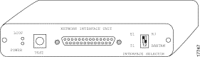
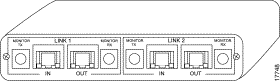
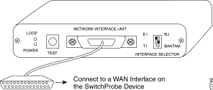
Figure 2 shows the rear panel of the T1/E1 WAN tap. The rear panel contains four RJ-48c ports—labeled IN and OUT, and four Bantam ports—labeled Monitor TX and Monitor RX.
Connecting the WAN SwitchProbe device to a network segment is a two-stage process:
To connect a T1/E1 WAN tap to the SwitchProbe device, see Figure 3 and follow these steps:
Step 2 Connect the DB-26M (male) end of the 15-foot cable to one of the SwitchProbe device WAN interfaces (26-pin female connector).
Step 3 To monitor a T1 line, set the DIP switch (on the right front of the tap) to T1.
To monitor an E1 line, set the DIP switch to E1.
Step 4 To monitor RJ-48c connections, set the DIP switch to RJ.
To monitor Bantam connections, set the DIP switch to Bantam.
Because routers have many different types of connectors, there are many ways you can connect a tap to a network segment.
The following sections describe four common scenarios for connecting the T1/E1 WAN tap to a network segment:
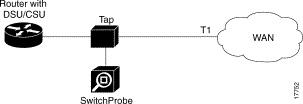
Figure 4 shows how to place the tap and SwitchProbe device between a router with a Data Service Unit (DSU) and a Channel Service Unit (CSU) connected to a WAN cloud.
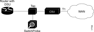
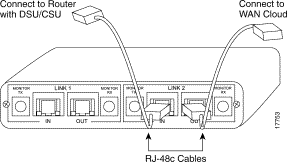
The T1/E1 WAN tap kit consists of two RJ-48c cables (among other cables). To connect the tap to a router with a DSU and a CSU, see Figure 5 and follow these steps:
Step 2 Connect the other end of this cable to the router (with DSU).
Step 3 Connect one end of the second RJ-48c cable to the tap port labeled OUT.
Step 4 Connect the other end of this cable to the CSU.
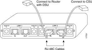
Figure 6 shows how to place the tap and SwitchProbe device between a router (with DSU/CSU) and a T1 line connected to a WAN cloud.
The T1/E1 WAN tap kit consists of two RJ-48c cables (among other cables). To connect the tap to a router (with DSU/CSU) and a WAN cloud, see Figure 7 and follow these steps:
Step 2 Connect the other end of this cable to the router (with DSU/CSU).
Step 3 Connect one end of the second RJ-48c cable to the tap port labeled OUT.
Step 4 Connect the other end of this cable to the WAN cloud.
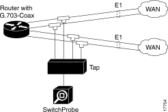
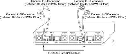
Figure 8 shows how to place the tap and SwitchProbe device between a router (with G.703-coax) and an E1 line connected to a WAN cloud.
The T1/E1 WAN tap kit consists of two RJ-48c-to-dual-BNC cables (among other cables). To connect the tap to a router (with G.703-coax) and a WAN cloud, see Figure 9 and follow these steps:
Step 2 Connect the other end of this cable (with dual BNC connectors) to a T-connector (between router and WAN cloud).
Step 3 Connect the end of the second cable (with RJ-48c connector) to the tap port labeled OUT.
Step 4 Connect the other end of this cable (with dual BNC connectors) to the T-connector (between router and WAN cloud).
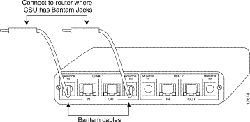
Figure 10 shows how to place the tap and SwitchProbe device between a router (where the CSU has Bantam jacks) and a T1/E1 line connected to a WAN cloud.
The T1/E1 WAN tap kit consists of Bantam jack cables (among other cables). To connect the tap to a router (where the CSU has Bantam jacks) and a WAN cloud, see Figure 11 and follow these steps:
Step 2 Connect the other end of this cable (with Bantam jacks) to the router (with CSU having Bantam jacks).
Step 3 Connect the end of the second cable (without Bantam jacks) to the tap port labeled OUT.
Step 4 Connect the other end of this cable (with Bantam jacks) to the router (where the CSU has Bantam jacks).
Depending on the CSU model, not all Bantam-to-Bantam connections will be successful. As an alternate, use the tap-to-router cabling method, using an RJ-48-to-Bantam cable as illustrated in Figure 12.
The T1/E1 WAN tap kit consists of RJ-48-to-Bantam jack cables (among other cables). To connect the tap to a router (where the CSU has Bantam jacks) and a WAN cloud, see Figure 12 and follow these steps:
Step 2 Connect the end of the cable (with RJ-48 connector) to the tap port
labeled IN.
Step 3 Connect the other end of this cable (with Bantam jacks) to the router (where the CSU has Bantam jacks).

Cisco Connection Online (CCO) is Cisco Systems' primary, real-time support channel. Maintenance customers and partners can self-register on CCO to obtain additional information and services.
Available 24 hours a day, 7 days a week, CCO provides a wealth of standard and value-added services to Cisco's customers and business partners. CCO services include product information, product documentation, software updates, release notes, technical tips, the Bug Navigator, configuration notes, brochures, descriptions of service offerings, and download access to public and authorized files.
CCO serves a wide variety of users through two interfaces that are updated and enhanced simultaneously: a character-based version and a multimedia version that resides on the World Wide Web (WWW). The character-based CCO supports Zmodem, Kermit, Xmodem, FTP, and Internet e-mail, and it is excellent for quick access to information over lower bandwidths. The WWW version of CCO provides richly formatted documents with photographs, figures, graphics, and video, as well as hyperlinks to related information.
You can access CCO in the following ways:
For a copy of CCO's Frequently Asked Questions (FAQ), contact cco-help@cisco.com. For additional information, contact cco-team@cisco.com.
Cisco documentation and additional literature are available in a CD-ROM package, which ships with your product. The Documentation CD-ROM, a member of the Cisco Connection Family, is updated monthly. Therefore, it might be more current than printed documentation. To order additional copies of the Documentation CD-ROM, contact your local sales representative or call customer service. The CD-ROM package is available as a single package or as an annual subscription. You can also access Cisco documentation on the World Wide Web at http://www.cisco.com, http://www-china.cisco.com, or http://www-europe.cisco.com.
If you are reading Cisco product documentation on the World Wide Web, you can submit comments electronically. Click Feedback in the toolbar and select Documentation. After you complete the form, click Submit to send it to Cisco. We appreciate your comments.
![]()
![]()
![]()
![]()
![]()
![]()
![]()
![]()
Posted: Thu Jul 25 04:49:41 PDT 2002
All contents are Copyright © 1992--2002 Cisco Systems, Inc. All rights reserved.
Important Notices and Privacy Statement.