|
|

This chapter provides the following information to enable you to plan and upload Native Service Point software to your NetView or NetMaster:
Use an IBM PC or compatible to upload CiscoWorks Blue Native Service Point software from a PC running IBM OS/2 or DOS to either an MVS, VM, or VSE host. This section describes the software and hardware requirements for the PC used to upload the CiscoWorks Blue Native Service Point software and the mainframe host requirements.
You must have the following operating system and software on your PC to upload Native Service Point software to your mainframe host.
To upload Native Service Point software to your mainframe host, your PC must meet the following minimum hardware requirements:
To use Native Service Point in your network, your mainframe host computer and Cisco routers must meet the following requirements:
Before you upload Native Service Point software to your MVS, VM, or VSE host, the following prerequisites must be met:
If these prerequisites are not met, you can still upload the Native Service Point software to a host, but you will not be able to view, access, or edit any router configurations.
To access a Cisco router by using Native Service Point from your NetView console, the Cisco router must be connected to the VTAM host. The MVS, VSE, or VM programmer should define the service point name (SPname) for each Cisco router in the VTAM configuration.
For each router in your network, add the following lines to your VTAM configuration, making sure you substitute the router name, IDBLK, and IDNUM variables for each router:
SWDRTRS VBUILD TYPE=SWNET
ROUTER_NAME PU ADDR=01                                     x
PUTYPE=2                                                   x
IDBLK=idblock number,                                      x
IDNUM=id number,                                           x
DISCNT=(NO),                                               x
ISTATUS=ACTIVE,                                            x
IRETRY=YES,                                                x
MAXOUT=7,                                                  x
PASSLIM=5,                                                 x
MAXPATH=4
SERVICE_POINT_NAME LU LOCADDR=locaddr,ISTATUS=status
Following is the syntax description for the router name, IDBLK, and IDNUM variables:
| router name | The service point name for the router. |
| idblock number | The idblock number that will be sent to the host during connection establishment. The block number 05D is recommended for routers. The XID value is 8 hexadecimal digits that include both Block and ID numbers. For example, if the XID value is 05D00001, the Block number is 05D and the ID number is 00001. |
| id number | The ID number for the router. |
Following is an example of a VTAM configuration for a router called glendusk with a service point name glendusk.
SWDRTRS VBUILD TYPE=SWNET                                 x
GLENDUSK PU ADDR=01 X                                     x
PUTYPE=2 X                                                x
IDBLK=05D                                                 x
IDNUM=BB000                                               x
DISCNT=(NO)                                               x
ISTATUS=ACTIVE                                            x
IRETRY=YES                                                x
MAXOUT=7                                                  x
PASSLIM=5                                                 x
MAXPATH=4                                                 x
GLENDUSK LU LOCADDR=02, ISTATUS=INACTIVE                  x
Your Cisco routers must be configured and connected to your network according to the instructions provided in the Cisco documentation. For detailed information about configuring Cisco routers, refer to the documentation list in the About This Guide section in this manual.
To access your Cisco routers by using Native Service Point, the following requirements should be met.
Your router's configuration must have the following specified:
In addition, your router's configuration must contain the commands shown in the section Minimum Router Configuration for Using Native Service Point.
If your routers are attached remotely to another router and require RSRB definitions, also use the additional sna host commands for RSRB that are described later in this chapter.
You can use Native Service Point to access your routers if each router's configuration contains the following commands:
sna host host-name xid-snd xid rmac remote-mac [rsap rsap-addr] [lsap local-sap] [focalpoint]
sna enable-host [lsap lsap-addr]
sna start [resource-name]
These commands are sufficient i f a router is directly connected to the host Token Ring and the router PU sends the XID directly to the Token Ring in a Source Route Bridging (SRB) frame. RSRB definitions are not used in this situation. See Figure 1-1 for an example.

Following is the syntax description for the sna host command:
| host-name | The specified SNA host. |
| xid-snd xid | The XID that will be sent to the host during connection establishment. The XID value is 8 hexadecimal digits and include both Block and ID numbers. For example, if the XID value is 05D00001, the Block number is 05D and the ID number is 00001. |
| rmac mac | The MAC address of the remote gateway, for example CIP or 3745.. |
| rsap remote-sap | [Optional] Specifies the SAP address used by the SNA to establish connection with the remote host. |
| lsap local-sap | [Optional] Specifies the the local SAP address used by the SNA to establish connection with the remote host. |
| focalpoint | Specifies that the host link will be used for the focal point support. |
The following command defines a link to an SNA host:
sna host CNM01 xid-snd 05dbb000 rmac 4001.3745.1088 rsap 4 lsap 4 focalpoint
Following is the syntax description for the sna enable-host command:
| lsap | [Optional] Activate a local SAP as an upstream SAP, for both receiving connectIn attempts and for starting connectOut attempts. |
| local-sap | Local SAP. The default is 12. |
The following example enables SNA on the interface and specifies that the local SAP 4 will be used for the session to the host:
sna enable-host lsap 4
Following is the syntax description for the sna start command:
| resource-name | The name of a host defined in a sna host command. |
The following example initiates a connection to CNM01:
sna start CNM01
This section explains sna host commands you add to your router's configuration if the following situation exists:
Figure 1-2 and Figure 1-3 show the physical and logical views of the router PUs attached to a remote Token Ring.

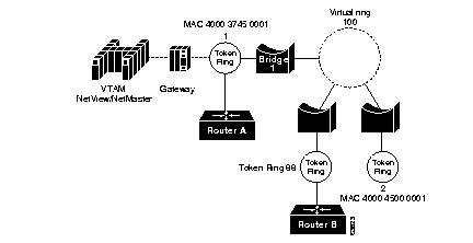
Router A's configuration contains the following router commands:
sna host host-name xid-snd xid rmac remote-mac [rsap rsap-addr] [lsap local-sap] [focalpoint]
sna enable-host [lsap lsap-addr]
sna start [resource-name]
Router B's configuration contains the following router commands:
sna host host-name xid-snd xid rmac remote-mac [rsap rsap-addr] [lsap local-sap] [focalpoint]
sna rsrb enable-pu [lsap local-sap]
The following example shows the defintion for a SNA host with CMP? and a connection to be established across an RSRB link:
sna rsrb 88 1 100 4000.4500.0001
sna rsrb enable-host lsap 10
sna host ibm3745 xid-snd 06500001 rmac 40 00.3745.0001 lsap 10
Following is the syntax description for the sna host command:
| host-name | The specified SNA host. |
| xid-snd xid | The XID that will be sent to the host during connection establishment. The XID value is 8 hexadecimal digits that include both Block and ID numbers. For example, if the XID value is 05D00001, the Block number is 05D and the ID number is 00001. |
| rmac remote mac | The MAC address of the remote host gateway. |
| rsap rsap-addr | [Optional] Specifies the SAP address used by the SNA to establish connection with the remote host. The default is 4. |
| lsap local-sap | [Optional] Specifies the the local SAP address used by the SNA to establish connection with the remote host. |
| focalpoint | Specifies the host link that will be used for the focal point support. |
Verify that routers in your network can be viewed from NetView. Use the following command at any command input prompt:
D Net, ID = router_nameThe router's status should display as ACTIV.
Verify that the routers in your network can be viewed from NetMaster. Use the following command at any command input prompt:
D router_nameThe router's status should display as ACTIV.
This section provides instructions on uploading Native Service Point for NetView and NetMaster:
Follow these instructions to upload Native Service Point CLISTs, panels, and .SEQ files for NetView to an MVS host.
Step 1 Insert the Native Service Point diskette into your PC's diskette drive.
Step 2 Log in to a TSO session using 3270. In the TSO session, make sure you are in the TSO command mode (ISPF option 6) or TSO (no ISPF).
Step 3 At the DOS or OS/2 command prompt in another window, enter the drive letter of the drive where the diskette is located. For example, if you are at the C:\ prompt in DOS and the diskette is in drive A, enter the following command and press Return:
Step 4 At the DOS or OS/2 prompt, enter the following command to upload the CLISTs and panels for MVS:
For example, if your diskette is located in drive A and the host session identifier is A, enter:
The CLISTs and panel members are uploaded in a BINARY and NOCRLF format to the MVS host by using the SEND command.
Step 5 Upload .SEQ files to the MVS host in a binary mode.
The record format (RECFM) of the receiving file must be a fixed block (FB) with a record size (LRECL) of 80.
The following message is displayed, indicating that the .SEQ files are being uploaded to the MVS host:
The Native Service Point files are copied to the MVS host.
Step 6 On your host session, using the ISPF option 3.4, enter the following command to search for the files you uploaded:
The prefix is your TSO ID prefix as specified in your profile.
The following message is displayed, indicating the files that are available:
CISCOSCL.SEQ contains the CLISTs and CISCOSPL.SEQ contains the panels.
Step 7 In the first line, press Tab to place the cursor before the first file (CISCOSCL.SEQ) and enter the following command:
Step 8 When prompted, press Enter.
The PDS is created.
Step 9 Press Tab to place the cursor before the file on the next line (CISCOSPL.SEQ) and enter the following command and press Enter:
Step 10 When prompted, press Enter.
Step 11 After the files are received, press PF3 and Enter to refresh the option 3.34 list.
The following files are displayed:
Step 12 Contact your MVS programmer to move the Native Service Point CLISTS to the user's CLIST (DSICLD) library and the the Native Service Point panels into the user's PANEL (CNMPNL1) library.
You are now ready to build a list of routers for accessibility through NetView and set up the automatic update of routers' status. After those steps are completed, the NetView operator is now ready to use Native Service Point to access, view, edit and manage the routers and their configurations from within NetView.
Follow these instructions to upload Native Service Point CLISTs, panels, and .SEQ files for NetView to a VM host.
Step 1 Insert the Native Service Point diskette into your PC's diskette drive.
Step 2 Log in to a CMS session using 3270.
Step 3 At the DOS or OS/2 command prompt in another window, enter the drive letter of the drive where the diskette is located. For example, if you are at the C:\ prompt in DOS and the diskette is in drive A, enter the following command and press Return:
Step 4 At the DOS or OS/2 prompt, enter the following command to upload the CLISTs and panels for VM:
For example, if you place your diskette in drive A and the host session identifier is A, enter:
The CLISTs and panel members are uploaded in a BINARY and NOCRLF format to the VM host by using the SEND command.
Step 5 After the members are uploaded to your CMS A disk, verify that nine CLISTs and 27 panels are available on the disk.
Step 6 Contact your VM programmer to move the Native Service Point CLISTS to the user's CLIST (DSICLD) library and the the Native Service Point panels into the user's PANEL (CNMPNL1) library.
You are now ready to build a list of routers for accessibility through NetView and set up the automatic update of routers' status. After those steps are completed, the NetView operator is now ready to use Native Service Point to access, view, edit and manage the routers and their configurations from within NetView.
Follow these instructions to upload Native Service Point CLISTs and panels for NetView to a VM host.
Step 1 Insert the Native Service Point diskette into your PC's diskette drive.
Step 2 Log into a CICS session using 3270.
Step 3 At the DOS or OS/2 command prompt in another window, enter the drive letter of the drive where the diskette is located. For example, if you are at the C:\ prompt in DOS and the diskette is in drive A, enter the following command and press Return:
For example, if you place your diskette in drive A and the host session identifier is A, enter:
vseuload A A
The CLISTs and panel members are uploaded in a BINARY and NOCRLF format to the VSE host by using the SEND command.
Step 4 After the members are uploaded to your CMS A disk, verify that nine CLISTs and 27 panels are available on the disk.
Step 5 Contact your VSE programmer to move the Native Service Point CLISTS to the user's CLIST (DSICLD) library and the the Native Service Point panels into the user's PANEL (CNMPNL1) library.
You are now ready to build a list of routers for accessibility through NetView and set up the automatic update of routers' status. After those steps are completed, the NetView operator is now ready to use Native Service Point to access, view, edit and manage the routers and their configurations from within NetView.
Follow these instructions to upload Native Service Point NCLs, panels, and .SEQ files for NetMaster to an MVS host. You will need the assistance of your MVS programmer to complete this procedure by moving the panels to the user's PANEL (CNMPNL1) library and renaming the $NWRUNCM NCL procedure as $NWRUNCX.
Step 1 Insert the Native Service Point diskette into your PC's diskette drive.
Step 2 Log into a TSO session using 3270. In the TSO session, make sure you are in the TSO command mode (ISPF option 6) or TSO (no ISPF).
Step 3 At the DOS or OS /2 command prompt in another window, enter the drive letter of the drive where the diskette si located. For example, if you are at the C:\ prompt in DOS and the diskette is in drive A, enter the following command and press Return:
Step 4 At the DOS or OS/2 prompt, enter the following command to upload the NCLs and panels to MVS:
For example, if you place your diskette in drive A and the host session identifier is A, enter:
The NCLs and panel members are uploaded in a BINARY and NOCRLF format to the MVS host by using the SEND command.
Step 5 Upload .SEQ files to the MVS host in a binary mode.
The record format (RECFM) of the receiving file must be a fixed block (FB) with a record size (LRECL) of 80.
The following message is displayed, indicating that the .SEQ files are being uploaded to the MVS host:
The Native Service Point files are copied to the MVS host.
Step 6 On your host session, using the ISPF option 3.4, substitute your TSO ID for prefix and enter the following command to search for the files you uploaded:
The prefix is your TSO ID prefix as specified in your profile.
The following message is displayed, indicating the files that are available:
CISCONCL.SEQ are NCL procedures and CISCONPL.SEQ are panels.
Step 7 In the first line, press Tab to place the cursor before the first file (CISCONCL.SEQ) and enter the following command:
Step 8 When prompted, press Enter.
The PDS is created.
Step 9 Press Enter and then press Tab to place the cursor before the file on the next line (CISCONPL.SEQ). Enter the following command and press Enter:
Step 10 When prompted, press Enter.
Step 11 After the files are received, press PF3 and Enter to refresh the option 3.4 list.
The following files are displayed:
CISCO.NCLPROCS contains the NCL procedures and jobs, CISCO.PNLBCKUP contains the reproed panels, CISCONCL.SEQ contains NCL procedures and jobs unloaded to PDS, and CISCONPL.SEQ contains panels.
Step 12 Enter B to view the data sets.
Step 13 Contact your MVS programmer to complete Steps 14 through 18.
Step 14 In the NCL procedures library, copy all the procedures except the PNLALLOC and PNLRESTR JOBS (available in the CISCO.NCLPROCS) to the NetMaster panels library.
Step 15 Edit the following statement using PNLRESTR and restore the panels to the NetMaster PANLUSR VSAM data set:
Step 16 Make a copy of the $NWRUNCM NCL procedure and rename it as $NWRUNCX.
Step 17 Change the UCASE to NOUCASE to ensure that the router data is not converted to uppercase.
Any changes in the NMMODS member should also be added to the $NWRUNCX routine. Other changes to the $NWRUNCX are optional. Do not use the sequence numbers in NMMODS. Use f (find) to locate the statements that need modifications.
Following is the sample output of the contents of a $NWRUNCX NCL procedure:
Step 18 Save the changes to the $NWRUNCX NCL procedure.
You are now ready to build a list of routers for accessibility through NetMaster and set up the automatic update of routers' status. After those steps are completed, the NetMaster operator is now ready to use Native Service Point to access, view, edit and manage the routers and their configurations from within NetMaster.
To view, access, and manage all of the routers in your network from NetView or NetMaster, build a list of accessible routers by editing the RTRSINIT CLIST (NetView) or RTRSINIT procedure (NetMaster).
Follow this procedure to build a list of routers for the NetView version of Native Service Point.
Step 1 Using a text editor, access the RTRSINIT CLIST.
Step 2 Enter the following line for each router you want to access from Native Service Point:
SPname is the service point name of the router, domain is the NetView name of the domain where the router is located, and host name is the router's host name as defined in the router's configuration.
The SPname is required. The domain name and host name are optional if your router is located within the local domain, but specifying these arguments is recommended.
The single quote before and after the SPname or before the SPname and after the host name is required.
Step 3 Repeat step 2 for each router you want to access from Native Service Point.
Step 4 If you want to define more than 28 routers for accessibility via Native Service Point (the maximum default value), add the following statement by substituting the number of routers:
For example, if you have 55 routers you want the NetView operator to access, enter the following command:
Step 5 Save the RTRSINIT CLIST.
Follow this procedure to build a list of routers for the NetMaster version of Native Service Point.
Step 1 Using a text editor, access the RTRSINIT NCL procedure.
Step 2 Enter the following line for each router you want to access via Native Service Point:
SPname is the service point name of the router, domain is the NetView name of the domain where the router is located, and host name is the router's host name as defined in the router's configuration.
The SPname is required. The domain name and host name are optional if your router is located within the local domain, but specifying these arguments is recommended.
Step 3 Repeat step 2 for each router you want to access via Native Service Point.
Step 4 If you want to define more than 28 routers for accessibility via Native Service Point (the maximum default value), add the following statement by substituting the number of routers:
For example, if you have 55 routers you want the NetMaster operator to access, enter the following command:
Step 5 Save the RTRSINIT NCL procedure.
To enable Native Service Point to automatically obtain and provide an updated status of your routers, the domains where they are located, and information of any operators that are logged in to the routers, your programmer needs to add certain commands to the NetView automation table or the NetMaster MSGPROC procedure.
If you use NetView, your programmer should complete this procedure to ensure that the latest status about your routers is available to you in Native Service Point.
Step 1 Add the following commands to the NetView automation table:
Step 2 If the IST5901 message already exists in the automation table, add the following commands before the existing entry your automation table:
Step 3 Save the updated automation table.
If you use NetMaster, your programmer should complete this procedure to ensure that the latest status about your routers is available to you in Native Service Point.
Step 1 Add the following commands to the MSGPROC procedure of the operator who will receive the VTAM messages:
Step 2 If the IST5901 message already exists in the procedure, add the following commands after the label in your MSGPROC procedure.
|
|