|
|

The following buttons are present in several windows. For brevity, they are described once here.
The IP Interface Parameters window, shown in Figure 9-1, is displayed when you click on the
IP button in the Interface Parameters window's View Parameters pane. The Interface Parameters window allows you to assign IP input and output access lists to the selected router interface, to turn on or off the split horizon feature, and to set EIGRP summary address attributes.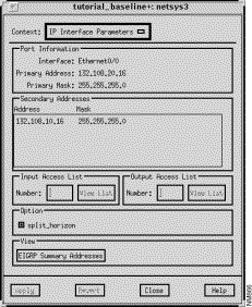
This window's components are described in the following sections. See "General Window Components" for a description of the Context, Apply, Revert, Close, and Help buttons.
Specify a number to be assigned to a standard or extended IP input access list for the selected interface, then press Return. If already defined in the configuration, it is displayed automatically. Click on the Apply button to assign the access list number to the input access list. At this point the Input Access List View List button is activated. Valid standard IP access list numbers range from 1 through 99. Valid extended IP access list numbers range from 100 through 199.
Click on this button to switch the context from the IP Interface Parameters window to one of the IP Access List windows. An input access list number must be selected and entered in the Input Access List Number field for the context switch to occur. If a standard IP access list number is specified (1 through 99), see "Standard IP Access List Window Components" for a detailed description of the Standard IP Access List window components. If an extended access list number is specified (100 through 199), see "Extended IP Access List Window Components" for a detailed description of the Extended IP Access List window components.
Specify a number to be assigned to a standard or extended IP output access list for the selected interface, then press Return. If already defined in the configuration, it is displayed automatically. Click on the Apply button to assign the access list number to the output access list. At this point the Output Access List View List button is activated. Valid standard IP access list numbers range from 1 through 99. Valid extended IP access list numbers range from 100 through 199.
Click on this button to switch the context from the IP Interface Parameters window to one of the IP Access List windows. An output access list number must be selected and entered in the Output Access List Number field for the context switch to occur. If a standard IP access list number is specified (1 through 99), see "Standard IP Access List Window Components" for a detailed description of the Standard IP Access List window components. If an extended access list number is specified (100 through 199), see "Extended IP Access List Window Components" for a detailed description of the Extended IP Access List window components.
Click on the split_horizon button to turn on/off the split horizon feature. The split horizon mechanism is used by routers connected to broadcast-type IP networks using distance vector routing protocols to prevent routing loops. Enabling split horizon blocks information pertaining to routes from being advertised by a router out any interface from which that information originated. It is recommended to not use the split horizon feature in nonbroadcast networks. Enabled is the default setting.
Click on this button to switch the context from the IP Interface Parameters window to the IP EIGRP Summary Addresses window. You can configure a summary aggregate address for this interface. If there are any more specific routes in the Routing Table, IP EIGRP advertises the summary address out the interface with a metric value equal to the minimum of all more specific routes. See "IP EIGRP Summary Address Window Components" for a detailed description of the IP EIGRP Summary Addresses window components.
The Standard IP Access List window, shown in Figure 9-2, is displayed when you specify a standard access list number in the Number field, press Return, click on the Apply button, and then click on the View List button in the IP Interface Parameters window. This window allows you to view, add, edit, and delete entries associated with the specified standard access list. The window's components are described in the following sections. See "General Window Components" for a description of the Context, Add Before, Add After, Edit, Delete, Apply, Revert, Close, and Help buttons. Clicking on the Add Before, Add After, and Edit buttons displays the Edit Standard IP Access List window. You can select a specific entry in the access list prior to clicking on the Add Before, Add After, or Edit buttons. See "Edit Standard IP Access List Window Components" for a detailed description of the window's components.
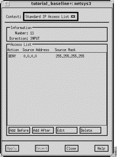
The standard IP access list number to be assigned to the selected interface is displayed in this field. Valid standard IP access list numbers range from 1 through 99.
The filter direction (INPUT or OUTPUT) of this standard IP access list for the selected interface is displayed in this field.
This pane lists the selected standard IP access list entry values. An entry contains the action (PERMIT/DENY), source address, and source mask values. These values are described in detail in the following section.
The Edit Standard IP Access List window, shown in Figure 9-3, is displayed when you click on the Add Before, Add After, or Edit buttons in the standard IP Access List window. This window allows you to add or modify a standard IP access list entry. Standard IP access list numbers range from 1 through 99.
This window's components are described in the following sections. See "General Window Components" for a description of the OK, Cancel, Help buttons.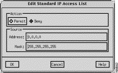
Select the Permit button to allow access from the specified source network and node addresses. Select the Deny button to block access from the specified source network and node addresses.
Specify a valid IP address as the source address, in dotted-decimal format, in this field.
The Extended IP Access List window, shown in Figure 9-4, is displayed when you have specified an extended access list number in the Number field and then clicked on the View List button in the IP Interface Parameters window. This window allows you to view, add, edit, and delete entries associated with the specified extended IP access list. Extended IP access list numbers range from 100 through 199.
This window's components are described in the following sections. See "General Window Components" for a description of the Context, Add Before, Add After, Edit, Delete, Apply, Revert, Close, and Help buttons. Clicking on the Add Before, Add After, and Edit buttons displays the Edit Extended IP Access List window. You can select a specific entry in the IP access list prior to clicking on the Add Before, Add After, or Edit buttons. See "Edit Extended IP Access List Window Components" for a detailed description of the window's components.
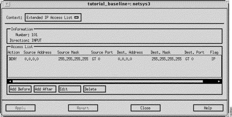
The extended IP output access list number assigned to the selected interface is displayed in this field. Valid extended IP access list numbers range from 100 through 199.
The filter direction for the selected router interface (INPUT or OUTPUT) is displayed in this field.
This pane lists the selected extended IP Input access list entry values. An entry contains the action (PERMIT/DENY), the source IP address, source IP mask, source port, destination IP address, destination IP mask, destination port, and flag values. These values are described in detail in "Edit Extended IP Access List Window Components."
The Edit Extended IP Access List window, shown in Figure 9-5, is displayed when you click on the Add Before, Add After, or Edit buttons in the Extended IP Access List window when using IOS 10.2 or earlier. When using IOS 10.3, a Source Port filter and equation values are also included. This window allows you to add or modify an extended access list entry. The window's components are described in the following sections. See "General Window Components" for a description of the OK, Cancel, and Help buttons.
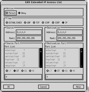
Select the Permit button to permit access from the specified source network and node address(es) and port number to the specified destination network and network node address(es) and port number. Select the Deny button to deny access from the specified source network and node address(es) and port number to the specified destination network and network node address(es) and port number. Deny is the default setting.
Click on one of the following buttons to select the desired transport protocol:
Selecting an ESTABLISHED, ICMP, IGRP, or IP flag automatically sets the port field to greater than zero (GT is selected.) This default setting can not be overridden. Selecting one of these flags values also deactivates the Source Port and Destination Port panes.
Specify a valid IP address as the source address, in dotted-decimal format, in this field.
Select a transmission protocol to use to send packets over the source router port from the list in this pane. The corresponding port number is displayed next to the entries. Selecting an entry from the list automatically selects the UDP or TCP flag. Selecting an ESTABLISHED, ICMP, IGRP, or IP flag deactivates the Source Port pane. The EQ source equation button is also automatically selected. Clicking on another destination equation value overrides the EQ setting.
Click on an equation value (LT (less than), GT (greater than), EQ (equal to), NE (not equal to)) button to set the source port equation value.
Specify a valid IP address as the destination address, in dotted-decimal format, in this field.
Select a transmission protocol to use to send packets to the destination router port from the list in this pane. The corresponding port number is displayed next to the entries. Selecting an entry from the list automatically selects the UDP or TCP flag. Selecting an ESTABLISHED, ICMP, IGRP, or IP flag deactivates the Destination Port pane. The EQ source equation button is also automatically selected. Clicking on another destination equation value overrides the EQ setting.
Click on an equation value (LT (less than), GT (greater than), EQ (equal to), NE (not equal to)) button to set the destination port equation value.
The IP EIGRP Summary Address window is displayed when you click on the View EIGRP Summary Addresses button in the IP Interface Parameters window. The IP EIGRP Summary Address window allows you to add, edit, and delete entries in the IP EIGRP summary address list. A summary aggregate address for this interface can be configured. If there are any more specific routes in the Routing Table, IP EIGRP advertises the summary address out the interface with a metric value equal to the minimum metric associated with all of the specific routes. This command works in conjunction with the EIGRP auto summary feature. If auto-summary is in effect, there is no need to configure network level summaries. The EIGRP summary addresses are ignored. See "EIGRP Option - Auto-Summary" for information about the EIGRP auto summary feature.
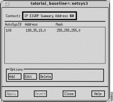
This window's summary address components are described below. See "General Window Components" for a description of the Context, Add, Edit, Delete, Apply, Revert, Close, and Help buttons. Clicking on the Add and Edit buttons displays the Edit IP EIGRP Summary Address List window. You can select a specific entry in the EIGRP Summary Address list prior to clicking on the Add or Edit buttons. See "Edit IP EIGRP Summary Address List Window Components" for a detailed description of the window's components.
The Edit IP EIGRP Summary Address window, shown in Figure 9-7, is displayed when you click on the Add or Edit buttons in the IP EIGRP Summary Address window. This window allows you to add or edit IP EIGRP summary address list entries. The window's components are described in the following sections. See "General Window Components" for a description of the OK, Cancel, Help buttons.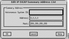
The IP address and IP address mask, in dotted-decimal format, are specified in these fields.
The IP Routing Table window, partially shown in Figure 9-8, is displayed when you click on the IP Routing Table button in the Router Configuration window. The IP Routing Table window displays the IP Routing Table entries configured for the router (netsys3 in this example.) This table is initially constructed from the information contained in the baseline router configuration files. Routing Tables generated during subsequent "what-if" scenarios also take into account the attributes that have been modified within those scenarios. IP Routing Table entries may not be edited from this window. Double-clicking on an IP Routing Table entry highlights the next hop router in the Topology window.
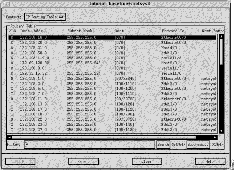
This window's components are described in the following sections. See "General Window Components" for a description of the Context, Apply, Revert, Close, and Help buttons.
The IP Routing Table pane displays a particular router's routing table entries. An IP routing table entry contains the routing algorithm, IP destination network address, IP destination address mask, administrative distance/cost factor, interface used to send packets to the next router along the path to the destination end system, and the next router in the path to the destination end system values.
Clicking on an IP Routing Table pane column header automatically sorts the information displayed in that column within the IP Routing Table pane accordingly. For example, when you click on the Forward to column header, the information displayed in the IP Routing Table pane is alphabetically sorted by the router's interface names.
netsys1 router is running EIGRP and summarizes route 16.17.17.0 255.255.255.0 to form 16.17.0.0 255.255.0.0, the following entry appears in netsys1's Routing Table:
D 16.17.0.0 255.255.0.0 [0/0] Null0
|
This corresponds to the following route that appears in netsys1's Routing Table after entering a show ip route command:
D 16.17.0.0 is a summary, 17:07:51, Null0
|
The protocol algorithm from which the IP Routing Table entry is derived from is displayed in this column. The possible values are provided in Table 9-1:
| Symbol | IP Protocol Algorithm Derived From |
|---|---|
| directly connected |
| EIGRP |
| external EIGRP |
| IGRP |
| OSPF route which is neither inter-area or external |
| external OSPF route having metric type 1 |
| external OSPF route having metric type 2 |
| OSPF route that crossed areas (inter-area OSPF route) |
| RIP |
| static |
| candidate default route |
| unknown derivation |
The IP subnet mask corresponding to the destination address is displayed in this column.
The first number displayed within the bracket is the administrative distance (trustworthiness) of the routing information source. Administrative distance values range from 0 to 255, inclusive. The general rule is the higher the value, the lower the trust rating. An administrative distance value of 255 signifies that the routing information source should not be trusted.
The second number is the metric for the route. For RIP, the metric is equal to hop count. For IGRP and EIGRP, the metric is a combination of segment delays and the lowest bandwidth for the route. In a network of mixed media, the route with the lowest metric generally equates to the most desirable path to the destination.
The next router in the path to the destination end system is displayed in this column. Double-clicking on a Routing Table entry highlights the next hop router in the Topology window.
You are able to use the Filter field to specify a specific algorithm, destination address, subnet mask, cost, or device to search for within each IP Routing Table entry. Pressing Return or clicking on the Search button initiates the search using the filter you have specified. The IP Routing Table entries containing text matching the search pattern are then displayed in the Routing Table pane. For example, if you wish to find all routes with a cost factor of 0/0, you would specify *\[0\/0\]* in the Filter field and then press Return or click on the Search button. Only the IP Routing Table entries containing routes with a cost factor of 0/0 are then displayed in the Routing Table pane.
The question mark is used to denote any one character. For example, if you specify *netsys?* in the Filter field, all IP Routing Table entries containing the string netsys and ending with any character are displayed in the Routing Table pane.
The negation operator (tilde) is used to denote the characters not to match on within the IP Routing Table. It is only allowed as the first character in the Filter field. For example, if you specify ~*132.* in the Filter field and then press Return or click on the Search button, all entries not containing the string 132. are displayed in the Routing Table pane.
Compound searches are also permitted. For example, if you wanted to display all IP Routing Table entries with destination addresses starting with 132.108 and whose next hop router is netsys8, you would enter *132.108*netsys8* in the Filter field and then press Return or click on the Search button.
Click on this button to initiate the search of the IP Routing Table using the filter you have specified in the Filter field. The number of IP Routing Table entries matching the specified filter and a total of all Routing Table entries are displayed within parentheses next to the Search button.
Click on this button to remove specified types of entries from the IP Routing Table. See "IP Suppress Entries Window Components" for detailed information about the Suppress Entries window components. The number of Routing Table entries being suppressed and a total of all Routing Table entries are displayed within parentheses next to the Suppress button.
The IP Suppress Entries window, shown in Figure 9-9, is displayed when you click on the Suppress button in the IP Routing Table window. This window allows you to specify the information you wish to keep from being included in the IP Routing Table being displayed. For example, you can specify to have all IGRP (I) related entries suppressed from the IP Routing Table by selecting the Add Suppression ALG button, specifying I in the ALG field, deselecting all other Add Suppression buttons, and then clicking on the Add button.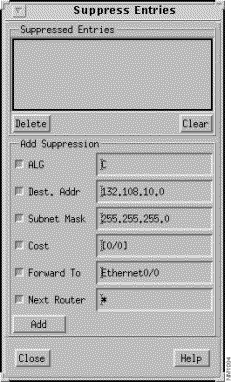
This window's components are described in the following sections. See "General Window Components" for a description of the Close and Help buttons. When you click on the Close button, the suppression parameters currently in effect are saved. When you subsequently invoke the Suppress Entries window, the suppression parameters that were in effect when the window was last closed remain in effect.
A list of the suppressed entries currently in effect are displayed in this pane. When an entry is added to this list, the IP Routing Table entries that match the suppression parameters are no longer displayed in the IP Routing Table. Initially suppression is not in effect, therefore the Suppressed Entries list is empty.
Select an entry from the Suppressed Entries list then click on this button to remove that entry from the list. The IP Routing Table entries that were suppressed due to this entry being in effect are redisplayed and the entry's suppression parameters are removed from existence.
Click on this button to remove all of the entries used to suppress IP Routing Table entries from the Suppressed Entries list. The IP Routing Table entries that were suppressed due to these entries being in effect are redisplayed and all suppression parameters are removed from existence.
The Add Suppression pane contains buttons related to the columns in the IP Routing Table window's Routing Table pane. Deselecting a button removes that category from suppression consideration. Select a button and then specify a value that when found within that column in an IP Routing Table entry, will cause that entry to be suppressed from the table. For example, if you want to suppress IP Routing Table entries that use the Ethernet0/0 interface to forward packets on to the next router, select the Forward To button, specify Ethernet0/0 in the button's text field, deselect the other Add Suppression buttons, then click on the Add button. All entries that contained Ethernet0/0 in the Forward To column are no longer shown in the IP Routing Table. The suppression number within the parentheses next to the Suppress button is updated to reflect the number of IP Routing Table entries currently being suppressed.
When you initially click on the Suppress button or create a suppression entry and add it to the Suppressed Entries list, all of the Add Suppression buttons in the Suppress Entries window are selected and their corresponding text fields contain the values associated with the selected entry in the IP Routing Table window. Clicking on the Add button at this point removes that entry from the IP Routing Table.
You can use the wild card character (an asterisk) to match any or all characters. When a field contains only an asterisk it is equivalent to specifying all items within that category. For example, specifying an asterisk in the ALG field, deselecting all other Add Suppression buttons, and then clicking on the Add button results in an empty IP Routing Table as the suppression mode was set to suppress entries for all protocol algorithms.
Select the ALG button and then specify the protocol algorithms whose entries you do not want included in the IP Routing Table, in the ALG field.
Select the Dest. Addr button and then specify the destination addresses whose entries you do not want included in the IP Routing Table, in the Dest. Addr field.
Select the Subnet Mask button and then specify the subnet mask whose entries you do not want included in the IP Routing Table, in the Subnet Mask field.
Select the Cost button and then specify the cost values whose entries you do not want included in the IP Routing Table, in the Cost field.
Select the Forward To button and then specify the symbolic router interfaces whose entries you do not want included in the IP Routing Table, in the Forward To field.
Select the Next Router button and then specify the name of the next router along the path to the destination whose entries you do not want included in the IP Routing Table, in the Next Router field.
Once you have selected the IP Routing Table category button(s) and specified the associated text in the button's text field(s), clicking on the Add button adds the suppression parameters to the Suppressed Entries list and initiates the suppression of the corresponding entries from the IP Routing Table. The number of entries currently being suppressed (displayed within parentheses next to the Suppression button in the IP Routing Table window) is updated accordingly.
When you click on the Close button, the suppression parameters currently in effect are saved. When you subsequently invoke the Suppress Entries window, the suppression parameters that were in effect when the window was last closed remain in effect.
The IP Static Routes window, shown in Figure 9-10, is displayed when you click on the IP Static Routes button in the Router Configuration window. This window allows you to view, modify, and delete IP Static Route entries defined for the router. The initial list of entries is specified by the ip route global configuration command in the router configuration file. Static routes are generally appropriate when a router cannot dynamically build a route to a destination.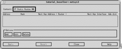
This window's components are described in the following sections. See "General Window Components" for a description of the Context, Add, Edit, Delete, Apply, Revert, Close, and Help buttons. Clicking on the Add and Edit buttons displays the Edit IP Static Routes List window. See "Edit IP Static Routes List Window Components" for a detailed description of the window's components.
The IP address, in dotted-decimal format, of the target network or subnet is displayed in this column.
The symbolic name of the router interface on the next router along the path to the target network is displayed in this column.
The Edit IP Static Routes List window, shown in Figure 9-11, is displayed when you click on the Add or Edit buttons in the IP Static Routes window. You can select a specific entry in the list of IP Static Routes prior to clicking on the Add or Edit buttons. You can add or modify an existing IP static route entry in a router configuration file using this window.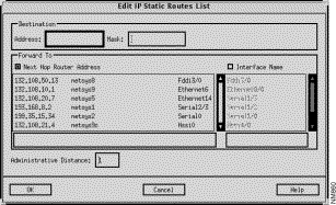
Specify the IP address, in dotted-decimal format, of the destination network in this field.
Specify the network mask, in dotted-decimal format, for the destination network in this field.
Click on this button to select the IP address of a router that is the next hop along the path to the target network. This button and the Interface Name button are mutually exclusive. Clicking on this button activates the Next Hop Router Address List. Select the desired next hop router entry from the list then click on the OK button.
Click on this button to select this router's interface to use to get to the next component along the path to the destination network. This button and the Next Hop Router Address button are mutually exclusive. Clicking on this button activates the Interface Name List. Select the desired interface entry from the list then click on the OK button. The null 0 entry is a special interface name providing an alternative method of filtering traffic. The overhead involved with using access lists can be avoided by directing undesired network traffic to the null interface.
The IP Routing Algorithms window, shown in Figure 9-12, is displayed when you click on the IP Algorithms button in the Router Configuration window. This window allows you to view and modify the IP routing algorithms configured for the router. The IP routing algorithms supported are Routing Information Protocol (RIP), Interior Gateway Routing Protocol (IGRP), Extended Interior Gateway Routing Protocol (EIGRP), and Open Shortest Path First (OSPF).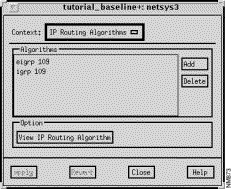
This window's components are described in the following sections. See "General Window Components" for a description of the Context, Add, Delete, Apply, Revert, Close, and Help buttons. Clicking on the Add button displays the Edit IP Routing Algorithms List window. See "Edit IP Routing Algorithms List Window Components" for a detailed description of the window's components.
This pane displays a list of the IP Routing Algorithms (RIP, IGRP, EIGRP, and OSPF) available in the current router configuration, as specified by the router global configuration command in the router configuration file. To add an IP routing algorithm to the current list, click on the Add button. The Edit IP Routing Algorithms List window is displayed. See "Edit IP Routing Algorithms List Window Components" for detailed information about adding an IP routing algorithm to the Algorithms list. To delete an IP routing algorithm from the list of algorithms available in the current router configuration, select the appropriate routing algorithm from the Algorithms list, click on the Delete button, then click on the Apply button.
To view a particular routing algorithm's attributes, select the appropriate entry from the Algorithms list then click on the View Routing Algorithm button.
Select one of the listed IP routing algorithms supported from the Algorithms list, then click on this button to switch the context from the IP Routing Algorithms window to the selected RIP, IGRP, EIGRP, or OSPF Algorithm window. Depending on the routing protocol you selected from the Algorithms list, a RIP, IGRP, EIGRP, or OSPF Algorithm window, described in detail in subsequent sections, is displayed. As the RIP Algorithm window is a subset of the IGRP Algorithm window and the IGRP Algorithm window is a subset of the EIGRP Algorithm window, the RIP Algorithm window is discussed first, followed by the additional fields in the IGRP Algorithm window, followed by the additional fields in the EIGRP Algorithm window.
Information about the corresponding routing protocol attributes is shown in the displayed Algorithms window. You can add and modify new attributes or you can delete existing routing protocol attributes.
The Edit IP Routing Algorithms List window, shown in Figure 9-13, is displayed when you click on the Add button in the IP Routing Algorithms window. This window allows you to add an IP routing algorithm to the list of routing algorithms supported in the current router configuration. See "General Window Components" for a description of the OK, Cancel, and Help buttons.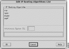
Specify the Autonomous System ID in this field. An autonomous system is a collection of interconnected routers under common management control, or similar routing policies and requirements. Typically, an autonomous system consists of routers connecting multiple IP network numbers. Autonomous System IDs must be assigned to the IGRP, EIGRP, and OSPF routing protocols. Routers originating from one autonomous system that need to be advertised into other autonomous systems must be redistributed.
The appropriate RIP/OSPF/IGRP/EIGRP Algorithms windows are displayed when you select a routing protocol from the Algorithms list in the IP Routing Algorithms window, and then click on the View Routing Algorithm button. These windows allow you to view and modify the routing protocol algorithm attributes being used by the router.
The RIP and OSPF Algorithm windows and attributes are the same except where noted. Therefore, only a snapshot of the RIP Algorithm window is shown in this section. As the RIP Algorithm window is a subset of the IGRP Algorithm window and the IGRP Algorithm window is a subset of the EIGRP Algorithm window, the RIP algorithm window is used as the basis for the IGRP and EIGRP algorithm window discussions. Therefore, the RIP Algorithm window, shown in Figure 9-14, is discussed in this section. All of the attributes described in the RIP Algorithm window apply to the IGRP and EIGRP windows as well. The additional fields in the IGRP Algorithm window are described in "IGRP/EIGRP Algorithm Window." The additional fields in the EIGRP Algorithm window are described in "EIGRP Algorithm Window."
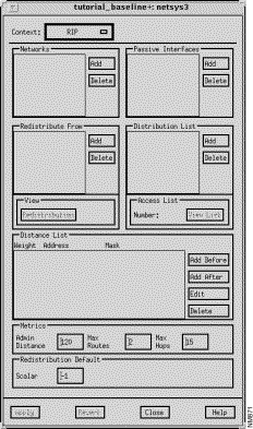
The window's components that are applicable to all four IP routing protocols are described in the following sections. See "General Window Components" for a description of the Context, Add Before, Add After, Edit, Delete, Apply, Revert, Close, and Help buttons. Clicking on the Add Before, Add After, and Edit buttons in the Distance List pane displays the Edit Distance List window. You can select an entry in the Distance List pane prior to clicking on the Add Before, Add After, and Edit buttons. See "Edit Distance List Window Components" for a detailed description of the window's components. To delete an entry from one of the lists displayed in the windows, select the entry, click on the associated Delete button, then click on the Apply button.
The basic algorithm window is comprised of the following panes which are described in subsequent sections:
This pane lists the IP network addresses of the networks directly connected to this router, as specified by the network router subcommand(s) in the router configuration file. RIP/IGRP/EIGRP routing updates will be sent and received only through interfaces on these networks. If an interface's network is not specified, it will not be advertized in any RIP/IGRP/EIGRP routing updates.
IGRP 109 is added to the Redistribute From list in the RIP Algorithm window, IGRP 109 routing updates with the specified metrics, if any, are redistributed to the RIP routing process.This pane lists this router's interfaces and filter directions, as specified by the distribute-list router subcommand that are applied to this routing protocol. Interfaces and access lists can be added to or deleted from this list. The filters update what the router learns or advertises. If the filter direction is set to input, the access list is used to filter networks received in routing updates. If the filter direction is set to output, the access list is used to suppress networks from being advertised in routing updates.
This pane allows the Distance list entries, as specified by the distance router subcommand in the router configuration file, to be viewed and modified.
This pane allows the RIP/OSPF/IGRP/EIGRP algorithm's administrative distance, maximum routes, and maximum hop metric values to be viewed and modified.
| Routing Source | Default Value |
|---|---|
Connected Interface | 0 |
Static Route | 1 |
EIGRP | 90 |
IGRP | 100 |
OSPF | 110 |
RIP | 120 |
The global default scalar value for the redistributed route, as specified by the default-metric router command, can be specified in this field. This results in the RIP/OSPF routing protocol using the same scalar metric value for all learned routes redistributed from the IGRP or EIGRP routing protocols. Since RIP/OSPF and IGRP/EIGRP have incompatible metrics, using the default scalar metric provides a reasonable substitute and enables redistribution to proceed. The default for RIP and OSPF is -1 which equates to no global default scalar being set.
Setting the metrics in this field automatically propagates these values to the metrics in the Redistribute From window. If you then set the metrics in the Redistribution window, the metric values in the Redistribution window take precedence over the Redistribution Default metrics. Otherwise, the values from Redistribution Default metrics are used.
The Edit Network List window is displayed when you click on the Add button in the Network pane of the RIP/IGRP/EIGRP Algorithm window. This window allows you to add the IP network number of a network directly connected to this router to the Networks list in the RIP/IGRP/EIGRP Algorithm window. See "General Window Components" for a description of the OK, Cancel, and Help buttons.
The network addresses of the networks directly connected to this router are displayed in this pane. To add an entry to the Networks list in the Algorithm window, select an entry in this list then click on the OK button. The directly connected network's network address is displayed in the Networks list in the Algorithm window.
The Edit Redistribution List window, shown in Figure 9-15, is displayed when you click on the Add button in the Redistribute From pane of the RIP/OSPF/IGRP/EIGRP Algorithm window. This window allows you to add a routing algorithm to the Redistribute From list. See "General Window Components" for a description of the OK, Cancel, and Help buttons.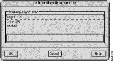
The Redistribution window, shown in Figure 9-16, is displayed when you select a routing algorithm entry from the Redistribute From list in the RIP Algorithms window, and then click on the Redistribution button. This window allows you to view and modify the parameters associated with the redistribution of routing information. A router can redistribute information from one routing protocol to another, as specified by the redistribute router subcommand in the router configuration file. Adding routing algorithms to the Redistribute From list allows routing information from the protocols in the Redistribute From list to be redistributed to the routing protocol in context. For example, if IGRP 109 is added to the Redistribute From list in the RIP Algorithm window, IGRP 109 routing updates are redistributed to the RIP routing process. See "General Window Components" for a description of the Apply, Revert, Close, and Help buttons.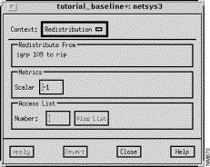
This pane displays the pair of routing algorithms the redistribution applies to.
The scalar value for the redistributed route, as specified by the redistribute protocol metric scalar_value router command, can be specified in this field. This results in the RIP and OSPF routing protocols using the same scalar metric value for all learned routes redistributed from the IGRP or EIGRP routing protocols. Since RIP/OSPF and IGRP/EIGRP have incompatible metrics, using the default scalar metric provides a reasonable substitute and enables redistribution to proceed. Specifying a value in this field overrides the global redistribution scalar value set in the RIP Algorithm window's Redistribution Defaults Scalar field. The default is -1 which equates to no default scalar metric being set.
Setting the metrics in this field automatically propagates these values to the metrics in the Redistribute From window. If you then set the metrics in the Redistribution window, the metric values in the Redistribution window take precedence over the Redistribution Default metrics. Otherwise, the values from Redistribution Default metrics are used.
Specify a standard IP access list number to filter redistributed routes in this field, press Return, then click on the Apply button. Valid standard IP access list numbers range from 1 through 99. This corresponds to the standard access list number as specified by the distribute-list access-list-number out protocol command.
Click on this button to switch the context from the Redistribution window to the Redistribution Filter List window. An access list number must be entered in the Access List Number text field for the context switch to occur. See "Redistribution Filter List Window Components" for a detailed description of the Redistribution Filter List window components.
The Redistribution window, shown in Figure 9-17, is displayed when you select the RIP routing algorithm entry from the Redistribute From list in the Algorithms window, and then click on the Redistribution button. In this case, this window allows you to view and modify parameters associated with the redistribution of routing information from the RIP routing algorithm to the IGRP routing algorithm.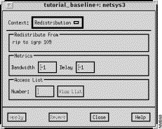
This pane displays the pair of routing algorithms the redistribution applies to.
Specify a standard IP access list number to filter redistributed routes in this field, press Return, then click on the Apply button. Valid standard IP access list numbers range from 1 through 99. This corresponds to the standard access list number as specified by the distribute-list access-list-number out protocol command.
Click on this button to switch the context from the Redistribution window to the Redistribution Filter List window. An access list number must be entered in the Access List Number text field for the context switch to occur. See "Redistribution Filter List Window Components" for a detailed description of the Redistribution Filter List window components.
The Redistribution window, shown in Figure 9-18, is displayed when you select a routing algorithm entry from the Redistribute From list in the OSPF Algorithms window, and then click on the Redistribution button. This window allows you to view and modify the parameters associated with the redistribution of routing information. A router can redistribute information from one routing protocol to another, as specified by the redistribute router subcommand in the router configuration file. Adding routing algorithms to the Redistribute From list allows routing information from the protocols in the Redistribute From list to be redistributed to the routing protocol in context. For example, if rip is added to the Redistribute From list in the OSPF Algorithm window, RIP routing updates are redistributed to the OSPF routing process. See "General Window Components" for a description of the Apply, Revert, Close, and Help buttons.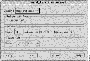
This pane displays the pair of routing algorithms the redistribution applies to.
Specify a standard IP access list number to filter redistributed routes in this field, press Return, then click on the Apply button. Valid standard IP access list numbers range from 1 through 99. This corresponds to the standard access list number as specified by the distribute-list access-list-number out protocol command.
Click on this button to switch the context from the Redistribution window to the Redistribution Filter List window. An access list number must be entered in the Access List Number text field for the context switch to occur. See "Redistribution Filter List Window Components" for a detailed description of the Redistribution Filter List window components.
The Redistribution Filter List window, shown in Figure 9-19, is displayed when you select an access list number and then click on the View List button in the Redistribution window. This window allows you to view, add, edit, and delete entries associated with the selected access list number from the Redistribution Filter list. See "General Window Components" for a description of the Context, Add Before, Add After, Edit, Delete, Apply, Revert, Close, and Help buttons. Clicking on the Add Before, Add After, and Edit buttons displays the Edit Redistribution Filter List window. You can select an entry in the Redistribution Filter list prior to clicking on the Add Before, Add After, and Edit buttons. See "Edit Redistribution Filter List Window Components" for a detailed description of the window's components.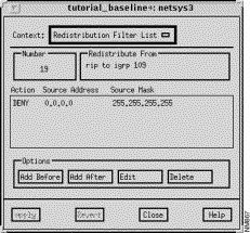
This field displays the selected standard IP access list number. Valid standard IP access list numbers range from 1 through 99.
This pane displays the pair of distinct routing algorithms the redistribution is to occur between.
The Action column specifies either PERMIT or DENY. PERMIT allows redistribution of the specified address. DENY denies redistribution of the specified address.
The source IP address is displayed in this column.
The source IP address mask is displayed in this column.
The Edit Redistribution Filter List window, shown in Figure 9-20, is displayed when you click on the Add Before, Add After, and Edit buttons in the Redistribution Filter List window. This window allows you to add or modify a Redistribution Filter list entry. See "General Window Components" for a description of the OK, Cancel, and Help buttons.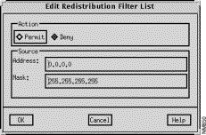
Click on either the Permit or Deny toggle button to control whether networks matching the address/mask are redistributed. Those denied are not passed to the routing protocol in context.
Specify a valid IP address, in dotted-decimal format, in this field.
The Edit Passive Interface List window is displayed when you click on the Add button in the Passive Interfaces pane of the RIP/OSPF/IGRP/EIGRP Algorithm window. This window allows you to select and add a passive interface to the routing protocol configuration. See "General Window Components" for a description of the OK, Cancel, and Help buttons.
A list of the router interfaces is displayed. Select an entry from the list, then click on the OK button to add that interface to the Passive Interface list. Passive router interfaces are disabled from sending routing updates. They are able to receive routing updates.
The Edit Distribution List window, shown in Figure 9-21, is displayed when you click on the Add button in the Distribution List pane of the RIP/OSPF/IGRP/EIGRP Algorithm window. This window allows you to select and add an interface and filter direction (input or output) to the router's Distribution list. See "General Window Components" for a description of the OK, Cancel, and Help buttons.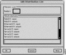
Specify a standard IP access list number to be assigned to the selected IP routing protocol in this field. Valid standard IP access list numbers range from 1 through 99.
This pane lists the available interfaces and filtering direction (input or output) that can be added to the router's Distribution List. Select an entry from the list, then click on the OK button. Special values are all input and all output which apply to all input and output interfaces, respectively.
The Distribution Filter List window, shown in Figure 9-22, is displayed when you select a Distribution List entry in the RIP/OSPF/IGRP/EIGRP Algorithm window and then click on the View List button. This window allows you to view, add, edit, and delete the entries associated with the selected access list number. See "General Window Components" for a description of the Context, Add Before, Add After, Edit, Delete, Apply, Revert, Close, and Help buttons. Clicking on the Add Before, Add After, and Edit buttons displays the Edit Distribution Filter List window. You can select an entry in the Distribution Filter list prior to clicking on the Add Before, Add After, and Edit buttons. See "Edit Distribution Filter List Window Components" for a detailed description of the window's components.
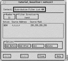
The selected standard IP access list number applied to the routing updates sent or received through the interface is displayed in this field. Valid standard IP access list numbers range from 1 through 99.
The Action column is set to either PERMIT or DENY. PERMIT allows distribution of the specified address. DENY denies distribution of the specified address.
The IP network address is displayed in this field in dotted-decimal format.
The Edit Distribution Filter List window, shown in Figure 9-23, is displayed when you click on the Add Before, Add After, and Edit buttons in the Distribution Filter List window. This window allows you to create or modify a Distribution Filter list entry.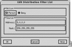
Click on either the Permit or Deny toggle button to set the action mode, accordingly. You select the Permit button to allow distribution of the specified address. Select the Deny button to deny distribution of the specified address.
Specify a valid IP address, in dotted-decimal format, as the Source Address in this field.
The Edit Distance List window, shown in Figure 9-24, is displayed when you click on the Add Before, Add After, and Edit buttons in the Distance List pane in the RIP/OSPF/IGRP/EIGRP Algorithm window. This window allows entries in the RIP/OSPF/IGRP/EIGRP Algorithms window's Distance List to be modified.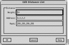
Specify the IP address, in dotted-decimal format, of a router or group of routers to which the weight value applies in this field.
Specify the IP address mask, in dotted-decimal format, of the target network in this field.
The IGRP/EIGRP Algorithm window allows you to view and modify all of the router's routing protocol attributes described in "RIP/OSPF/IGRP/EIGRP Algorithm Windows," as well as IGRP/EIGRP specific attributes. This window is displayed when you select an EIGRP or IGRP entry in the Algorithms list in the IP Routing Algorithms window and then click on the View IP Routing Algorithm button. The IGRP/EIGRP Algorithm window is the same as the RIP Algorithm window with a few additional fields. The additional fields are shown in Figure 9-25.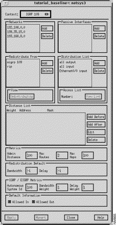
Global bandwidth and delay redistribution metric values can be specified in the corresponding fields in this window pane. Setting the metrics in this field automatically propagates these values to the metrics in the Redistribute From window. If you then set the metrics in the Redistribution window, the metric values in the Redistribution window take precedence over the Redistribution Default metrics. Otherwise, the values from Redistribution Default metrics are used.
The following IGRP and EIGRP metrics can be specified:
Click on the Allowed In or Allowed Out button to control exterior information between IGRP/EIGRP processes, as specified by the default_information allowed [in/out] command. Default information allowed in permits IGRP exterior or default routes to be received by an IGRP process. Default information allowed out permits IGRP exterior routes to be advertised in updates. The default for both buttons is on.
The EIGRP Algorithm window allows you to view and modify all of the router's routing protocol attributes described in "RIP/OSPF/IGRP/EIGRP Algorithm Windows" and in "IGRP/EIGRP Algorithm Window," as well as EIGRP specific attributes. This window is displayed when an EIGRP entry in the Algorithms list in the IP Routing Algorithms window is selected and the View IP Routing Algorithm button is clicked. The EIGRP Algorithm window is the same as the IGRP/EIGRP Algorithm window with additional external administrative distance metric and auto summary options.
Specify the external administrative distance value for EIGRP external routes in this field. External routes are those for which the best path is learned from a neighbor external to the autonomous system. The default external administrative distance metric value is 170.
Click on this toggle button to turn the Auto Summary feature on/off. This is used to perform automatic summarization of subnet routes into network level routes. For example, 133.106.1.0 can be configured to be advertised as 133.106.0.0 over interfaces that have subnets of 192.31.7.0 configured. Automatic summarization is performed when there are two or more network router configuration commands configured for the IP EIGRP process. By default, this feature is not enabled.
This command works in conjunction with EIGRP summary addresses in which additional summarization can be performed. If auto-summary is in effect, there is no need to configure network level summaries. The EIGRP summary addresses are ignored. See "IP EIGRP Summary Address Window Components" for information about EIGRP summary addresses.
The IP Default Networks window, shown in Figure 9-26, is displayed when you click on the IP Default Networks button in the Router Configuration window. This corresponds to the ip default-network network command which is used to specify a network as a candidate route for computing the gateway of last resort. This window allows you to view, add, edit, and delete entries associated with the Default Networks List.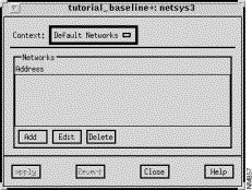
This window's components are described in the following sections. See "General Window Components" for a description of the Context, Add, Edit, Delete, Apply, Revert, Close, and Help buttons. Clicking on the Add and Edit buttons displays the Edit Default Networks List window. See "Edit Default Networks List Window Components" for a detailed description of the window's components.
The addresses of the default networks for this router configuration are displayed in this pane.
The Edit Default Networks List window is displayed when you click on the Add or Edit buttons in the Default Networks window. You can select a specific entry in the Default Networks window prior to clicking on the Add or Edit buttons. The Edit Default Networks List window allows you to add an entry to the router's Default Networks List. See "General Window Components" for a description of the OK, Cancel, and Help buttons.
A list of the default networks are displayed in this pane. To add a new default network to the list, specify its name in the text field below this pane then click on the OK button.
The IP Access List Summary window, shown in Figure 9-27, is displayed when you click on the
IP Access List button in the Router Configuration window. This window allows you to view the existing IP access list numbers applied to the interfaces and/or routing algorithms.
If values appear in the Access List, Interface, and Direction columns and the Algorithm column is blank, the access list is applied to an interface.
If values appear in the Access List, Interface, and Direction columns, and one algorithm is listed in the Algorithm column, the access list is applied to an distribution.
If values appear in the Access List, Interface, and Direction columns, and two algorithms are listed in the Algorithm column (e.g. igrp 109 -> rip), the access list is applied to a redistribution.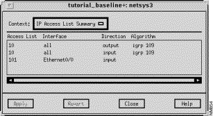
This window's components are described in the following sections. See "General Window Components" for a description of the Close and Help buttons.
Existing IP access list numbers are displayed in this column.
The router interfaces the IP access list numbers are applied to are displayed in this column.
The filter direction (Input, Output, Both) the IP access list number is applied to is displayed in this column.
The IP routing algorithms (where appropriate) the access list number is applied to are displayed in this column.
|
|