|
|

This chapter describes the following windows displayed as a result of selecting options from the Connectivity Tools window's File and Options menus:
The windows described in the chapters listed below are available for viewing network element configuration attributes when using the Connectivity Baseliner. The chapters are:
Various windows in this section contain buttons that provide like functionality. For brevity purposes, these buttons are described in this section.
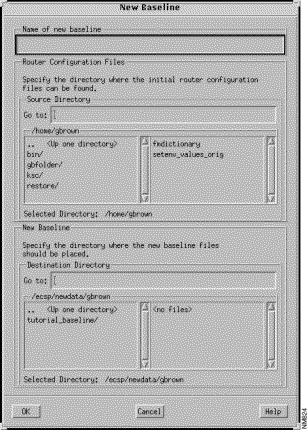
The New Baseline window, shown in Figure 3-1, is displayed when the File>New Baseline menu option in the Connectivity Tools window is selected. This option provides a mechanism for creating a new baseline from the provided router configuration files. Once a new baseline is created, it can be opened and loaded by selecting the File>Open Baseline menu option in the Connectivity Tools window. See "Open Baseline Window" for detailed information about the Open Baseline menu option.
The components of this window are described below. See "General Window Components" for a description of the OK, Cancel, and Help buttons.
Specify the unique name of the new baseline in this field. A baseline with the same name can not already exist in the destination directory.
Specify the location of the router configuration files in the Source Directory Go to field then press Return. Navigation through the directories can also be accomplished by double-clicking on an entry in the list of directories. The Selected Directory field displays the current directory either specified or navigated to. The default directory is your home directory.
Specify the directory where the new baseline files should be placed in the Destination Directory Go to field then press Return. Navigation through the directories can also be accomplished by double-clicking on an entry in the list of directories. The Selected Directory field displays the current directory either specified or navigated to. The default directory is the location specified by the ECSP_DATA environment variable.
Click on the OK button to create a new baseline directory in the location specified. The router configuration files are copied into the new baseline directory under SCCS control.
The Open Baseline window is displayed when the File>Open Baseline menu option in the Connectivity Tools window is selected. The format of the Open Baseline window is dependent upon whether you are using the Connectivity Baseliner or Connectivity Solver. As the Connectivity Baseliner does not support the Analysis and Routing Table options, they are not present in the Connectivity Baseliner's Open Baseline window. The Open Baseline window shown in Figure 3-2 is displayed when you are using the Connectivity Solver.
The Open Baseline window allows you to open and load an existing baseline thereby creating the baseline scenario and, when using the Connectivity Solver, compute the Routing Tables according to the Analysis and Routing Table options you specify.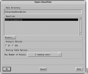
The components of this window are described below. See "General Window Components" for a description of the OK, Cancel, and Help buttons.
Specify the directory where existing baselines are located, in this field. If the ECSP_DATA environment variable is set, its value is displayed in this field. To specify an alternative directory, enter the directory path in the Data Directory text field then press Return.
The baselines located in the directory specified in the Data Directory field are displayed in this pane. Select the baseline you want to open from the Baselines list.
When you double-click on an entry in the Baselines list or select an entry and then click on the OK button, the selected baseline is loaded and an initial baseline scenario, using the baseline name as its name, is created. An entry for this initial baseline scenario is displayed and selected in the Connectivity Tools window's Scenarios list. The following Connectivity Baseliner features are now available through the Connectivity Tools window:
Return to "Connectivity Baseliner" and "Connectivity Solver" for detailed information about the tasks that can be accomplished using the Connectivity Baseliner and Connectivity Solver.
Click on the Routers button to display the list of routers associated with the selected baseline, in the Routers window, as shown in Figure 3-3.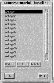
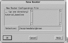
To add a new router to the baseline configuration, click on the Add button. The New Router window, shown in Figure 3-4, is displayed. Specify the location and name of the new router's configuration file in the Selection field, press Return, then click on the OK button. If a router with the same name you are attempting to add already exists in this baseline, you are given the option of replacing the existing router configuration file with the new one. The default path in the Selection field is the location specified by the ECSP_DATA environment variable.
To edit a router's router configuration file, select the router from the list of routers, then click on the Edit button. The editor specified by the EDITOR environment variable is used to view or edit the selected router's configuration file. Depending on the file access permissions in place, the file can be opened in read only or read/write mode. Upon making the desired changes, click on the OK button.
To delete a router from the baseline, select the router from the list of routers, then click on the Delete button.
Select the IP and/or IPX analysis buttons to select the type of routing protocol analysis to be performed on the baseline network. The default is to perform both IP and IPX analysis. If your network uses only one of the routing protocols, deselect the other routing protocol button prior to clicking on the OK button. Even if your network supports both protocols you may want to select only one protocol for analysis as the process can be resource intensive.
The Delete Baseline window, shown in Figure 3-5, is displayed when the File>Delete Baseline menu option in the Connectivity Tools window is selected. This option allows an existing baseline to be deleted from the baselines directory specified by the ECSP_DATA environment variable.
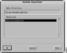
The components of this window are described below. See "General Window Components" for a description of the OK, Cancel, and Help buttons.
Specify the directory where existing baselines are stored in this field. If the ECSP_DATA environment variable is set, its value is displayed in this field. To specify an alternate directory, enter the directory path in this field, then press Return.
A list of existing baselines found in the directory specified in the Data Directory field are displayed in this pane. Select the baseline entry to be deleted, then click on the OK button. Click on the Cancel button to dismiss the Delete Baseline window.
The Export Baseline window, as shown in Figure 3-6, is displayed when the File>Export Baseline menu option in the Connectivity Tools window is selected. This option allows modified baseline router configuration files used for network simulation and/or analysis, to be saved. The router configuration files can then be used in another program or with routers in a work environment.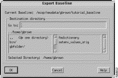
The components of this window are described below. See "General Window Components" for a description of the OK, Cancel, and Help buttons.
Specify the directory where the router configuration files are to be saved to in the Go to field, then press Return. The directories and files located in the current directory are displayed in the panes below the Go to field. Directories are listed in the left pane, files in the right pane. The default directory is your home directory. Navigation through the directories can be accomplished by double-clicking on an entry in the directory list. The Selected Directory field displays the current directory either specified or navigated to. Click on the OK button when the desired location is reached or specified.
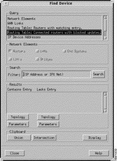
The Find Device window, shown in Figure 3-7, is used to search for network elements by name or address (routers, links, and LAN components) and within router Routing Table entries. The search mechanism can also be used in conjunction with the Clipboard to collect sets of network elements for batch analysis purposes. It is displayed by selecting the Options>Find Device menu option in the Connectivity Tools window.
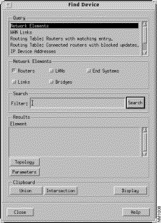
The components of this window are described below. See "General Window Components" for a description of the Close and Help buttons.
Select this entry to search for network elements by name. The Network Elements buttons and Filter field are used in conjunction with this type of search. The results of the search are displayed in the Results pane.
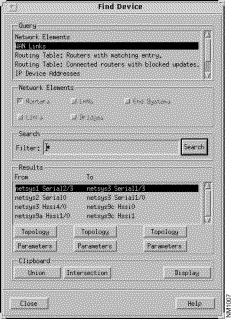
Select this Query entry to search for serial interconnections. To search for all WAN links, use the default filter (asterisk) and click on the Search button. Upon completing the search, entries containing the names of the routers on both ends of the links and their interfaces, matching the filter you specified, are displayed in the Results pane.
When this Query mode is selected, the Find Device window, shown in Figure 3-8, contains three sets of Topology and Parameters buttons. See "Results - Topology Button(s)" and "Results - Parameters Button(s)" for information about these buttons.
Select this Query entry to search for routers with an IP Routing Table entry matching the IP address specified in the Filter field or to search for routers with an IPX Routing Table entry matching the IPX network address specified in the Filter field. The results of the search are displayed in the Results pane. An IP or IPX network address must be specified in the Filter field when this query option is selected.
Select this Query entry to search for connected routers where one of the connected routers has an IP or IPX Routing Table entry matching the IP or IPX network address specified in the Filter field, while the other connected router does not have an IP or IPX Routing Table entry matching the IP or IPX network address specified in the Filter field. An IP or IPX network address must be specified in the Filter field when this query option is selected. When you click on this button, the format of the Find Device window changes, as shown in Figure 3-9. The results of this search are displayed in the Results pane. The connected routers with an IP or IPX Routing Table entry matching the IP or IPX network address specified in the Filter field are listed in the Contains Entry column while the routers without an IP or IPX Routing Table entry matching the IP or IPX network address specified in the Filter field are listed in the Lacks Entry column.
When this Query mode is selected, the Find Device window contains two sets of Topology and Parameters buttons. Each set is associated with the Contains Entry and Lacks Entry columns in the Results pane. See "Results - Topology Button(s)" and "Results - Parameters Button(s)" for information about these buttons.
Select this Query entry to search for network elements by IP address. Upon completing the search, qualifying IP addresses and their corresponding router names are displayed in the Results pane. The Results list is sorted by the IP addresses.
Select this Query entry to search for network elements by IPX address. Upon completing the search, qualifying IPX addresses and their corresponding router names are displayed in the Results pane. The Results list is sorted by the IPX addresses.
Select this Query entry to search for Remote Source-Route Bridging peers. Upon completing the search the RSRB peer's ring group name and the peer router names and their addresses are displayed in the Results pane.
Click on a network element button to select that network element type to search for. Multiple device types can be selected as parameters for a single search. You can search for routers, LANs, end systems, links, and bridges. Searching for Routing Table entries and RSRB Peers are relative to routers only, therefore the Routers button is selected by default and all of the Network Elements buttons are deactivated when queries of these types are selected.
You are able to use the Filter field to specify a network element name or network element address to search for. Pressing Return or clicking on the Search button initiates the search using the filter you have specified. The results of the search are then displayed in the Results pane.
Special characters are available for your use. The backslash character is used as a means to escape special characters. The wild card character (an asterisk) is used to match any character. For example, if you selected Network Elements as the query mode, Routers as the network element type, specified net* in the Filter field and then clicked on the Search button, a list of the routers whose names begin with net are displayed in the Results pane. If the Filter field contained only an asterisk (the default search mode) in the above example, the names of all routers existing in the current baseline are displayed in the Results list.
The question mark is used to denote any one character. For example, if in the previous example you specified netsys? in the Filter field, all routers whose names begin with netsys and end with any character are listed in the Results list.
The negation operator (a tilde) is used to denote the characters not to match on during the search. It is only allowed as the first character in the Filter field. For example, if you did not want to display IP devices with an address beginning with 132, you would specify ~132* in the Filter field and click on the Search button. All IP devices whose IP address did not start with 132 are then displayed in the Results pane.
Compound searches are also permitted. For example, if you want to find routers whose names do not start with net and end with 6 and whose IP address does not start with 132, you would specify ~132* net*6 in the Filter field and then click on the Search button. An existing router named netsys6 with an IP address starting with any number other than 132 is displayed in the Results list after the completion of the search.
Click on this button to initiate the search. The search process uses the selections specified in the Query, Network Elements, and Filter fields as search parameters. The results of the search are displayed in the window's Results pane.
Selecting an entry in the Results list highlights the corresponding network element's icon and displays its name or address in the Topology window, if it is already displayed. Double-clicking on a Results entry displays the corresponding Router/LAN/Link/End System configuration window.
Depending on the query mode you have specified, the Find Device window will have from one to three Topology buttons displayed.
Click on this button, after having selected an entry in the Results list, to highlight the corresponding network element's icon in the Topology window (if it is already displayed.)
When the query is set to Routing Table: Connected routers with blocked updates, two Topology buttons are displayed in the Find Device window. The buttons are associated with the Contains Entry and Lacks Entry columns in the Results pane. When you select a Results list entry and then click on a Topology button, the router icon associated with that entry is highlighted in the Topology window (if it is already displayed.)
When the query is set to WAN Links, three Topology buttons are displayed in the Find Device window. Upon selecting an entry in the Results list, clicking on the left Topology button highlights the corresponding link in the Topology window (if it is already displayed.) Clicking on the middle Topology button highlights the router icon listed in the From column of the Results list in the Topology window (if it is already displayed). Clicking on the right Topology buttonhighlights the router icon listed in the To column of the Results list in the Topology window (if it is already displayed).
The results of clicking on this button depends on the type of query you invoke. On network element searches, clicking on this button displays the Router/LAN/Link Configuration window pertaining to the network element selected in the Results list. For example, if you select the netsys1 router entry in the Results list and then click on the Parameters button, the netsys1 Router Configuration window, containing the netsys1 router attributes, is displayed.
When the query mode is Routing Table: Routers with matching entry, clicking on this button displays a Router Configuration window corresponding to the router selected in the Results list.
When the query mode is Routing Table: Connected routers with blocked updates, two Parameters buttons are displayed in the Find Device window. The buttons are associated with the Contains Entry and Lacks Entry columns in the Results pane and are used to display the corresponding router's Router Configuration window. For example, to display the Router Configuration window for a router in the Contains Entry column, select the appropriate entry in the Results list then click on the Parameters button displayed below that column.
When the query is set to WAN Links, three Parameters buttons are displayed in the Find Device window. Upon selecting an entry in the Results list, clicking on the left Parameters button displays the Link Configuration window pertaining to the selected entry's WAN link. Clicking on the middle Parameters button displays the Router Configuration window pertaining to the selected entry's router listed in the From column of the Results list. Clicking on the right Parameters button displays the Router Configuration window pertaining to the selected entry's router listed in the To column of the Results list.
The buttons in the Clipboard pane are used to add the search results to the Results pane in the Clipboard window and to display or bring to the front of the screen the Clipboard window. See "Clipboard Window" for a detailed information about the Clipboard window.
Click on this button to merge the entries in the search Results pane with the entries in the Clipboard window's Results pane, if they do not already exist. This is equivalent to doing a logical OR operation.
Click on this button to save the entries that exist in both the Find Device and Clipboard window's Results panes. If none of the entries exist in both windows, the Results pane in the Clipboard window is cleared. This is equivalent to doing a logical AND operation.
Click on this button to display the Clipboard window.
The Clipboard window, shown in Figure 3-10, allows you to save and merge the results of various queries performed in the Find Device window and to perform the batch processing actions listed in the Batch Analysis Actions list when using the Connectivity Solver. See Chapter 6 in the Enterprise/Solver Connectivity Tools User's Guide for a tutorial describing the use of the batch analysis capabilities. You display the Clipboard window by clicking on the Display button in the Find Device window or by selecting the Options>Show Clipboard menu option in the Connectivity Tools window.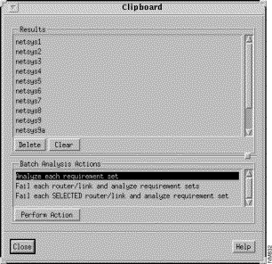
The components of this window are described below. See "General Window Components" for a description of the Close and Help buttons.
The Results list is populated from the Find Device window's Results list. Network elements, and where applicable, their addresses and other pertinent information, displayed in the Find Device window's Results list can be added to or merged with the existing entries in this list. See "Clipboard" for a description of how the Find Device window's Results list entries are added to or merged with the entries in this list.
When you click on an entry in this list its corresponding network element icon in the Topology window is highlighted and its name, symbolic name, or address is displayed.
Select the entries you want to delete from the Results list then click on this button to delete them.
Click on this button to delete all entries from the Results list.
A list of the batch analysis actions you can perform is displayed in this pane. Double-clicking on a Batch Analysis Actions list entry or selecting a Batch Analysis Actions list entry and then clicking on the Perform Action button initiates that action. The batch analysis actions currently available are:
Select the action you want performed, and if necessary, the device/link(s) from the Results list, then click on this button to initiate that action. The Batch Analysis window is then displayed. See "Batch Analysis Window" for a detailed description of the Batch Analysis window.
The Batch Analysis window is displayed when you select an action you want performed, and if necessary the device/link(s) from the Results list in the Clipboard window, and then click on the Perform Action button. Figure 3-11 is an example of the Batch Analysis window that is displayed when the Analyze each requirement set batch analysis action option in the Clipboard window was selected and the Perform Action button was clicked.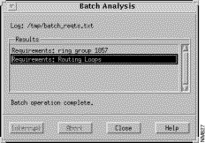
The components of this window are described below. See "General Window Components" for a description of the Close and Help.
The log file /tmp/batch_reqts.txt is created when the Analyze each requirement set batch processing action is initially selected. The results of the analysis performed on each of the Connectivity Requirements that currently exist by this action are saved to this log file on an ongoing basis.
The log file /tmp/batch_fail.txt is created when either of the Fail each router/link... batch processing actions are initially selected. The results of the analysis performed on each of the Connectivity Requirements that currently exist by these actions are saved to this log file on an ongoing basis.
Information pertaining to the batch analysis action currently being performed is displayed in this list on an ongoing basis until the batch analysis action is complete.
Click on this toggle button to interrupt the batch analysis action currently being executed. When you click on this button, it becomes a Resume button. Click on the Resume button to resume the batch analysis option that you had previously interrupted.
Click on this button to terminate the batch analysis action currently being executed.
|
|