|
|

Table Of Contents
Management VPN in the Cable Network
Cable VPN Configuration Overview
Provisioning Cable Services in ISC
Creating a Cable Subinterface Service Request
Creating Cable Link Service Requests
Provisioning Cable Services
This chapter describes how to provision MPLS VPN cable in IP Solutions Center (ISC). It contains the following sections:
•
Provisioning Cable Services in ISC
•
Overview of MPLS VPN Cable
Using MPLS VPN technology, service providers can create scalable and efficient private networks using a shared Hybrid Fiber Coaxial (HFC) network and Internet Protocol (IP) infrastructure. The cable MPLS VPN network consists of the following two major elements:
•
•
Benefits of Cable MPLS VPNs
Provisioning cable services with MPLS VPNs provides the following benefits:
•
Service providers can create scalable and efficient VPNs across the core of their networks MPLS VPNs provide systems support scalability in cable transport infrastructure and management.
•
•
MSOs can partner with ISPs to deliver multiple services from multiple ISPs and add value within the MSO's own network using VPN technology.
•
•
MPLS VPN provides systems support domain selection, authentication per subscriber, selection of QoS, policy-based routing, and ability to reach behind the cable modem to subscriber end-devices for QoS and billing, while preventing session-spoofing.
•
The Cable MPLS VPN Network
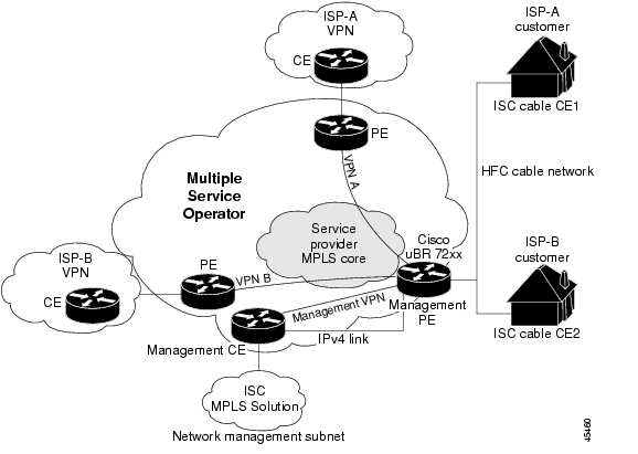
As shown in Figure 10-1, each ISP moves traffic to and from a subscriber's PC, through the MSO's physical network infrastructure, to the ISP's network. MPLS VPNs, created in Layer 3, provide privacy and security by constraining the distribution of VPN routes only to the routers that belong to its network. Thus, each ISP's VPN is insulated from other ISPs that use the same MSO infrastructure.
In the MPLS-based cable scheme, a VPN is a private network built over a shared cable plant and MPLS-core backbone. The public network is the shared cable plant or backbone connection points. A cable plant can support Internet access services and carry traffic for an MSO and its subscribers, as well as for multiple Internet Service Providers (ISPs) and their subscribers.
An MPLS VPN assigns a unique VPN Routing/Forwarding (VRF) instance to each VPN. A VRF instance consists of an IP routing table, a derived forwarding table, a set of interfaces that use the forwarding table, and a set of rules and routing protocols that determine the contents of the forwarding table.
Each PE router maintains one or more VRF tables. If a packet arrives directly through an interface associated with a particular VRF, the PE looks up a packet's IP destination address in the appropriate VRF table. MPLS VPNs use a combination of BGP and IP address resolution to ensure security.
The routers in the cable network are as follows:
•
•
•
•
•
•
The shared cable plant supports Internet connectivity from ISP A to its subscribers and from ISP B to its subscribers.
Figure 10-1 Example of an MPLS VPN Cable Network
Management VPN in the Cable Network
The MPLS network has a unique VPN that exclusively manages the MSOs devices called the management VPN. It contains servers and devices that other VPNs can access. The management VPN connects the Management CE (MCE) router and the management subnet to the MSO PE router (a uBr72xx router or equivalent). ISC and the management servers, such as Dynamic Host Configuration Protocol (DHCP), Cisco Network Registrar (CNR) Time of Day (ToD) are part of the management subnet and are within the management VPN for ISP connectivity. For an explanation of the management VPN, see "Provisioning Management VPN."
As shown in Figure 10-1, the management VPN is comprised of the network management subnet (where the ISC workstation resides), which is directly connected to the Management CE (MCE). The management VPN is a special VPN between the MCE and the cable VPN gateway. The cable VPN gateway is usually a Cisco uBR 72xx router that functions as both a regular PE and a Management PE. Notice that there is also a parallel IPv4 link between the MCE and the MPE.
Cable VPN Configuration Overview
Cable VPN configuration involves the following:
•
•
Note
To configure MPLS VPNs for cable services, the MSO must configure the following:
•
•
Tip
•
•
•
•
The MSO must determine the primary IP address range. The primary IP address range is the MSO's address range for all cable modems that belong to the ISP subscribers.
The ISP must determine the secondary IP address range. The secondary IP address is the ISP's address range for its subscriber PCs.
To reduce security breaches and differentiate DHCP requests from cable modems in VPNs or under specific ISP management, MSOs can use the cable helper-address command in Cisco IOS software. The MSO can specify the host IP address to be accessible only in the ISP's VPN. This lets the ISP use its DHCP server to allocate IP addresses. Cable modem IP address must be accessible from the management VPN.
In ISC, you specify the maintenance helper address and the host helper address and the secondary addresses for the cable subinterface.
Cable VPN Interfaces and Subinterfaces
In the cable subscriber environment, several thousand subscribers share a single physical interface. Configurations with multiple logical subinterfaces are a vital part of the MPLS VPN network over cable. You can configure multiple subinterfaces and associate a specific VRF with each subinterface. You can split a single physical interface (the cable plant) into multiple subinterfaces, where each subinterface is associated with a specific VRF. Each ISP requires access on a physical interface and is given its own subinterface. The MSO administrator can define subinterfaces on a cable physical interface and assign Layer 3 configurations to each subinterface.
The MPLS VPN approach of creating VPNs for individual ISPs or customers requires subinterfaces to be configured on the cable interface. One subinterface is required for each ISP. The subinterfaces are tied to the VPN Routing/Forwarding (VRF) tables for their respective ISPs.
You must create the maintenance subinterface on the cable interface and tie it to the management VPN. The maintenance interface is for the ISP's use, and it is used for VPN connectivity, as well as the management VPN using an extranet between the ISP and the management VPN.
ISC automatically selects the subinterface number based on the VRF. If a subinterface that is associated with the current VRF does not yet exist, ISC creates a subinterface and assigns it to the correct VRF. The subinterface number is incremented to 1 greater than the largest subinterface currently assigned for the selected cable interface.
The network management subnet (which includes the CNR, ToD, and ISC) can reply to the cable modem because the management VPN allows connectivity for one filtered route from the ISP's VPN to the Management CE (MCE). Similarly, in order to forward the management requests (such as DHCP renewal to CNR), the ISP VPN must import a route to the MCE in the management VPN.
Cisco uBR7200 series software supports the definition of logical network layer interfaces over a cable physical interface. The system supports subinterface creation on a physical cable interface.
Subinterfaces allow traffic to be differentiated on a single physical interface and associated with multiple VPNs. Each ISP requires access on a physical interface and is given its own subinterface. Using each subinterface associated with a specific VPN (and therefore, ISP) subscribers connect to a logical subinterface, which reflects the ISP that provides their subscribed services. Once properly configured, subscriber traffic enters the appropriate subinterface and VPN.
Provisioning Cable Services in ISC
The tasks you must complete to provision cable services in ISC are as follows:
•
•
•
When using the ISC to provision cable services, there are no CEs in the same sense there are when provisioning a standard MPLS VPN. Thus, you must use a PE-only policy or create a cable policy with no CE.
Creating the Service Requests
This section contains the following subsections:
•
•
Creating a Cable Subinterface Service Request
The cable maintenance subinterface on the PE is the means by which the cable device retrieves its own IP address. For this reason, the maintenance subinterface must be configured before provisioning cable services. To create a cable subinterface service request, perform the following steps:
Step 1
The Service Requests dialog box appears.
Step 2
A drop-down list is displayed, showing the types of service requests you can create.
Step 3
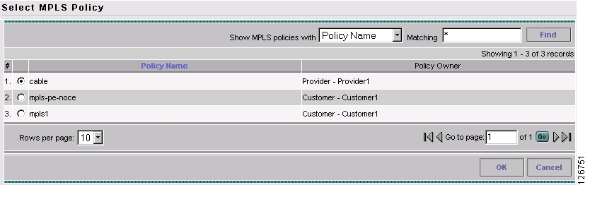
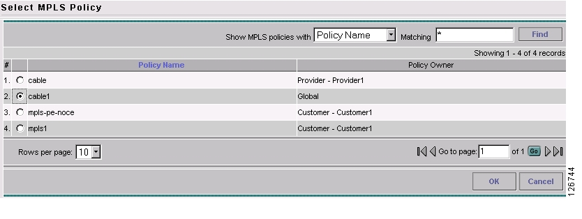
The Select MPLS Policy dialog box appears, as shown in Figure 10-2. This dialog box displays the list of all the MPLS service policies that have been defined in ISC.
Figure 10-2 Selecting the Cable Policy for the Subinterface
Step 4
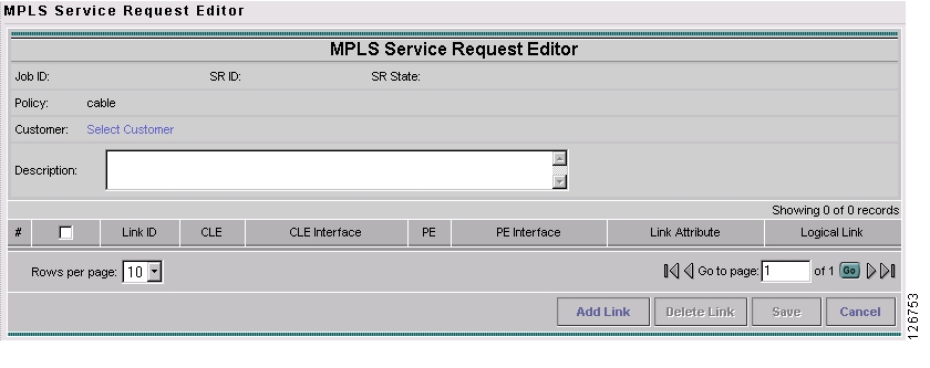
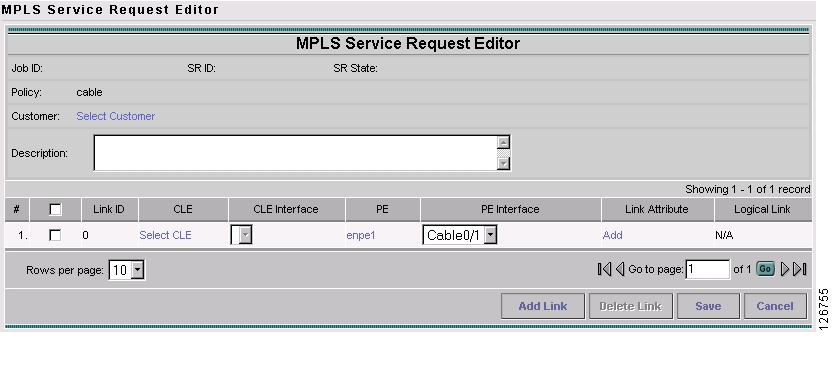
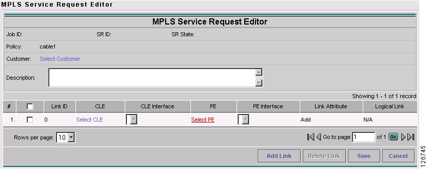
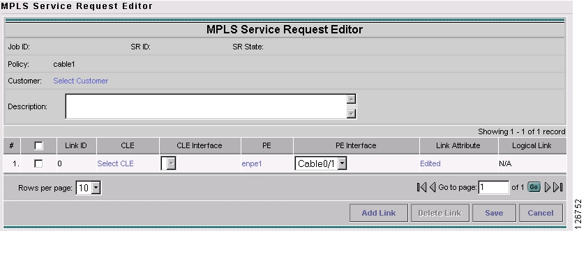
The MPLS Service Request Editor appears, as shown in Figure 10-3.
Figure 10-3 MPLS Service Request Editor
Step 5
The MPLS Service Request Editor now displays a set of fields. Notice that the Select PE field is enabled. Specifying the PE for the link is the first task required to define the link for this service.
Step 6
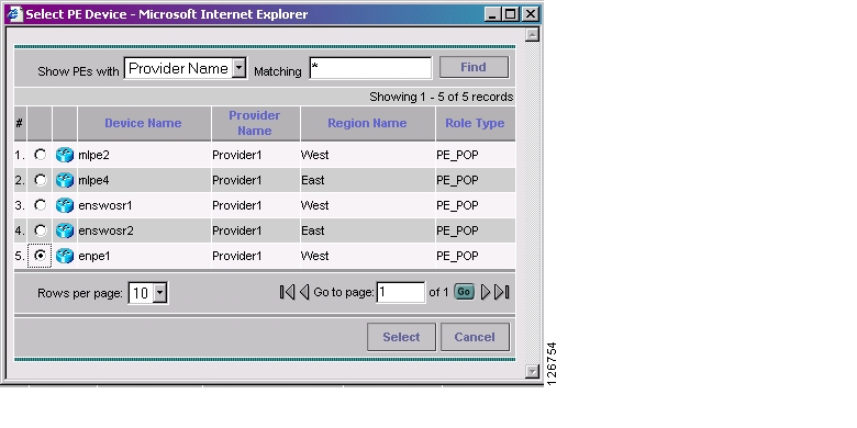
The Select PE Device dialog box appears, as shown in Figure 10-4.
Figure 10-4 Selecting the PE for the MPLS Link
Step 7
You return to the Service Request Editor window, where the name of the selected PE is now displayed in the PE column.
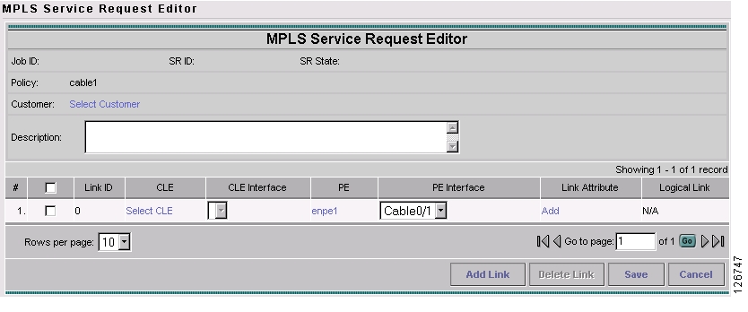
Step 8
Figure 10-5 PE and PE Interface Fields Defined
Only the major interface names are available for you to select. ISC assigns the appropriate subinterface number for each VPN.
The Link Attribute Add option is now enabled.
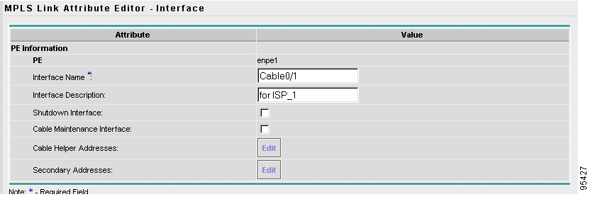
Step 9
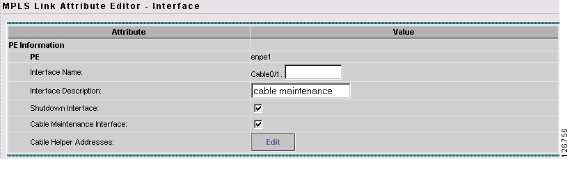
The MPLS Link Attribute Editor is displayed, showing the fields for the interface parameters, as shown in Figure 10-6.
Figure 10-6 Specifying the MPLS Link Interface Attributes
Step 10
Step 11
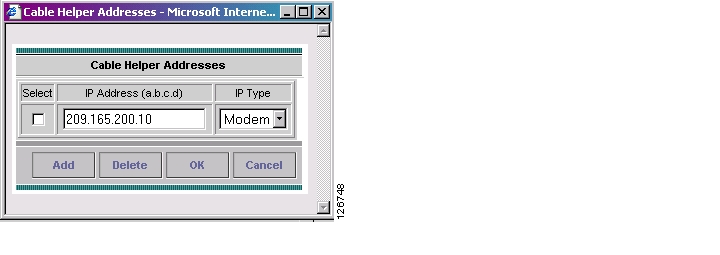
The Cable Helper Addresses window appears.
Step 12
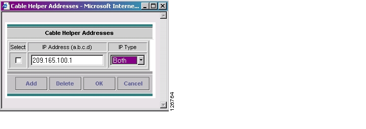
The Cable Helper Addresses window appears as shown in Figure 10-7.
Figure 10-7 Cable Helper Addresses
Step 13
Cable Modems and their attached CPE devices (hosts) will broadcast DHCP packets to the destination IP address, and this destination IP address is the configured cable helper address. So, from configured cable helper address, cable modems and their attached CPE (hosts) will receive their (CM and CPE) IP address.
IP Type can have the following values:
•
•
•
Step 14
The MPLS Link Attribute Editor reappears.
Step 15
The MPLS Link Attribute Editor - IP Address Scheme appears.
Step 16
The following routing protocol options are supported:
•
•
•
•
•
Because the service policy used for this service specified the routing protocol as editable, you can change the routing protocol for this service request as needed.
Step 17
The MPLS Link Attribute Editor for the VRF and VPN attributes appears. The field values displayed in this dialog box reflect the values specified in the service policy associated with this service.
Note
Step 18
Step 19
You return to the MPLS Service Request Editor.
Note
Step 20
You return to the Service Requests dialog box, where the information for the link you just defined is now displayed.
Creating Cable Link Service Requests
To create a cable link service request, perform the following steps:
Step 1
The Service Requests dialog box appears.
Step 2
A drop-down list is displayed, showing the types of service requests you can create.
Step 3
The Select MPLS Policy dialog box appears, as shown in Figure 10-8. This dialog box displays the list of all the MPLS service policies that have been defined in ISC.
Figure 10-8 Selecting the Cable Link Policy for This Service
Step 4
The MPLS Service Request Editor appears.
Step 5
The MPLS Service Request Editor now displays a set of fields, as shown in Figure 10-9. Note that in the PE column, the Select PE option is now enabled.
Figure 10-9 MPLS Service Request Editor
Step 6
The Select PE Device dialog box is displayed, as shown in Figure 10-10.
Figure 10-10 Selecting the PE for the MPLS Link
Step 7
You return to the Service Request Editor window, where the name of the selected PE is now displayed in the PE column.
Step 8
Figure 10-11 PE and PE Interface Fields Defined
Note that the Link Attribute Add option is now enabled.
Step 9
The MPLS Link Attribute Editor is displayed, showing the fields for the interface parameters, as shown in Figure 10-12.
Figure 10-12 Specifying the MPLS Link Interface Attributes
Note
Step 10
The Cable Helper Addresses window appears.
Step 11
The Cable Helper Addresses window appears as shown in Figure 10-13.
Figure 10-13 Cable Helper Addresses
Step 12
Cable Modems and their attached CPE devices (hosts) will broadcast DHCP packets to the destination IP address, and this destination IP address is the configured cable helper address. So, from configured cable helper address, cable modems and their attached CPE (hosts) will receive their (CM and CPE) IP address.
IP Type can have the following values:
•
•
•
Step 13
The MPLS Link Attribute Editor reappears.
Step 14
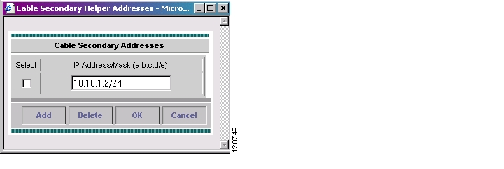
The Cable Secondary Addresses window appears. The secondary IP address enables CPE devices (hosts) attached to cable modem to talk to CMTS. (Usually this is a public IP address so that PCs can go to internet.)
Figure 10-14 Cable Secondary Addresses
Step 15
The MPLS Link Attribute Editor reappears.
Step 16
Step 17
Step 18
The MPLS Link Attribute Editor for Routing Information appears.
Step 19
The MPLS Link Attribute Editor for the VRF and VPN attributes appears. The field values displayed in this dialog box reflect the values specified in the service policy associated with this service.
Note
Step 20
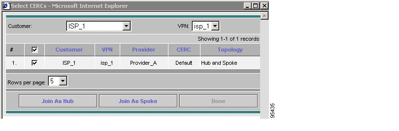
Step 21
The Select CERCs/VPN dialog box appears.
Figure 10-15 Choose CERCs
Step 22
Step 23
The MPLS Link Attribute Editor for the VRF and VPN attributes appears.
Step 24
You return to the MPLS Service Request Editor.
Note
Step 25
You return to the Service Requests dialog box, where the information for the link you just defined is now displayed.
Figure 10-16 Service Request for an MPLS Link Completed
Step 26
![]()
![]()
![]()
![]()
![]()
![]()
![]()
![]()
Posted: Mon Feb 18 15:03:36 PST 2008
All contents are Copyright © 1992--2008 Cisco Systems, Inc. All rights reserved.
Important Notices and Privacy Statement.