|
|

Table Of Contents
Provisioning Carrier Supporting Carrier
Carrier Supporting Carrier Overview
Backbone Network with ISP Customer Carrier
Backbone Network with BGP/MPLS VPN Service Provider Customer Carrier
Provisioning CSC Service Requests
Provisioning Carrier Supporting Carrier
This chapter describes how to configure the carrier supporting carrier (CSC) feature using the IP Solution Center (ISC) provisioning process. It contains the following sections:
•
Carrier Supporting Carrier Overview
•
•
Carrier Supporting Carrier Overview
The carrier supporting carrier feature enables one MPLS VPN-based service provider to allow other service providers to use a segment of its backbone network. The service provider that provides the segment of the backbone network to the other provider is called the backbone carrier. The service provider that uses the segment of the backbone network is called the customer carrier.
This documentation focuses on a backbone carrier that offers Border Gateway Protocol and Multiprotocol Label Switching (BGP/MPLS) VPN services. There can be two types of customer carriers:
•
•
This documentation describes both types of customer carrier.
It is transparent to the backbone provider when either scenario is in use, after the required functionality for basic MPLS VPN CSC is implemented in the backbone network.
Backbone Network with ISP Customer Carrier
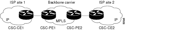
In this network configuration, the customer carrier has two sites, each of which is a point of presence (POP). The customer carrier connects these sites using a VPN service provided by a backbone carrier, who uses MPLS. The ISP sites use IP. To enable packet transfer between the ISP sites and the backbone carrier, the CSC-CE routers that connect the ISPs to the backbone carrier run MPLS.
Figure 11-1 shows a carrier supporting carrier network configuration where the customer carrier is an ISP. The customer carrier has two sites, each of which is a point of presence (POP). The customer carrier connects these sites using a VPN service provided by the backbone carrier. The backbone carrier uses MPLS. The ISP sites use IP. To enable packet transfer between the ISP sites and the backbone carrier, the CSC-CE routers that connect the ISPs to the backbone carrier run MPLS.
Figure 11-1 Carrier Supporting Carrier Network with an ISP Customer Carrier
In this example, only the backbone carrier uses MPLS. The customer carrier (ISP) uses only IP. As a result, the backbone carrier must carry all the Internet routes of the customer carrier, which could be as many as 100,000 routes. This poses a scalability problem for the backbone carrier. To solve the scalability problem, the backbone carrier is configured as follows:
•
•
Internal and external routes are differentiated this way:
•
•
The number of internal routes is much smaller than the number of external routes. Restricting the routes between the CSC-CE routers of the customer carrier and the CSC-PE routers of the backbone carrier significantly reduces the number of routes that the CSC-PE router needs to maintain.
Since the CSC-PE routers do not have to carry external routes in the VRF routing table, they can use the incoming label in the packet to forward the customer carrier Internet traffic. Adding MPLS to the routers provides a consistent method of transporting packets from the customer carrier to the backbone carrier. MPLS allows the exchange of an MPLS label between the CSC-PE and the CSC-CE routers for every internal customer carrier route. The routers in the customer carrier have all the external routes either through IBGP or route redistribution to provide Internet connectivity.
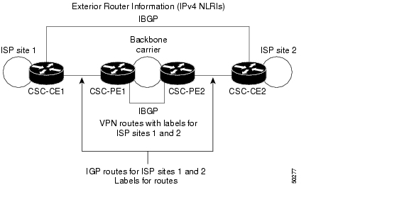
Figure 11-2 shows how information is exchanged when the network is configured in this manner.
Figure 11-2 Backbone Carrier Exchanging Routing Information with a Customer Carrier Who Is an ISP
Backbone Network with BGP/MPLS VPN Service Provider Customer Carrier
When a backbone carrier and the customer carrier both provide BGP/MPLS VPN services, the method of transporting data is different from when a customer carrier provides only ISP services. The following list highlights those differences.
•
•
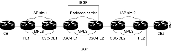
Figure 11-3 figure shows a carrier supporting carrier network configuration where the customer carrier is an MPLS VPN provider. The customer carrier has two sites. The backbone carrier and the customer carrier use MPLS. The IBGP sessions exchange the external routing information of the ISP.
Figure 11-3 Carrier Supporting Carrier Network with a Customer Carrier Who Is an MPLS VPN Provider
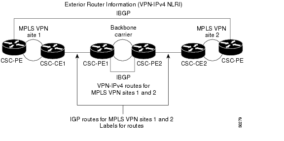
Figure 11-3 figure shows exchanging information with a customer carrier who is an MPLS VPN service provider.
Figure 11-4 Backbone Carrier Exchanging Information with a Customer Carrier Who Is an MPLS VPN Service Provider
ISC Configuration Options
To configure the CSC network to exchange routes and carry labels between the backbone carrier provider edge (CSC-PE) routers and the customer carrier customer edge (CSC-CE) routers, use Label Distribution Protocol (LDP) to carry the labels and an Internal Gateway Protocol (IGP) to carry the routes.
LDP/IGP
A routing protocol is required between the CSC-PE and CSC-CE routers that connect the backbone carrier to the customer carrier. The routing protocol enables the customer carrier to exchange IGP routing information with the backbone carrier. RIP, OSPF, or static routing as the routing protocol can be selected.
Label distribution protocol (LDP) is required between the CSC-PE and CSC-CE routers that connect the backbone carrier to the customer carrier. LDP is also required on the CSC-PE to CSC-CE interface for VPN routing/forwarding (VRF).
IPv4 BGP Label Distribution
BGP takes the place of an IGP and LDP in a VPN forwarding/routing instance (VRF) table. You can use BGP to distribute routes and MPLS labels. Using a single protocol instead of two simplifies the configuration and troubleshooting.
BGP is the preferred routing protocol for connecting two ISPs, mainly because of its routing policies and ability to scale. ISPs commonly use BGP between two providers. This feature enables those ISPs to use BGP.
When BGP (both EBGP and IBGP) distributes a route, it can also distribute an MPLS label that is mapped to that route. The MPLS label mapping information for the route is carried in the BGP update message that contains the information about the route. If the next hop is not changed, the label is preserved.
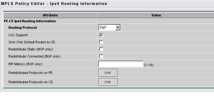
Defining CSC Service Policies
To define a Service Policy with CSC, choose the CSC Support check box from the MPLS Policy Editor - Routing Information, as shown in Figure 11-5.
Figure 11-5 CSC Service Policy
When CSC Support is checked, the CSC functionality is enabled to the MPLS VPN service.
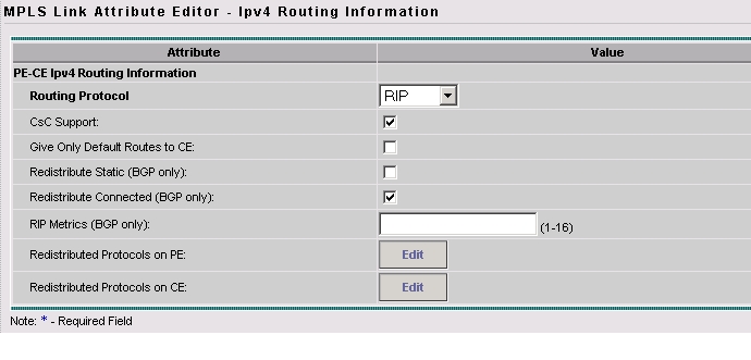
Provisioning CSC Service Requests
To provision a Service Request with CSC, choose the CSC Support check box from the MPLS Link Attribute Editor - Routing Information, as shown in Figure 11-6.
Figure 11-6 CSC Service Request
When CSC Support is checked, the CSC functionality is enabled for the MPLS VPN service.
![]()
![]()
![]()
![]()
![]()
![]()
![]()
![]()
Posted: Mon Feb 18 15:01:47 PST 2008
All contents are Copyright © 1992--2008 Cisco Systems, Inc. All rights reserved.
Important Notices and Privacy Statement.