This appendix describes how to identify faults (events or alarms) that a Cisco DSLAM generates on the network. When a fault occurs on a managed object in the network, CDM receives immediate notification. When you open the Cisco EMF Event Browser from the launchpad, a color next to the network object indicates the presence of an alarm.
SNMP traps raise alarms on CDM. You can detect the source of an alarm by using the Event Browser to navigate through the network object hierarchy to the affected object. Alarms are propagated up the element hierarchy according to severity (see Table A-2). All alarms are stored within the Event Browser, which displays both current and historical data. For further information on the Event Browser, refer to the Cisco Element Management Framework User Guide.
You can detect the source of an alarm by using the Event Browser window, or Event Browser, to navigate through the network object hierarchy to the affected object. Alarms propagate up the element hierarchy according to severity. The Event Browser displays events that the system flags.
The Event Browser stores all alarms and displays current as well as historical data. You can detect the presence of an alarm by the color that Cisco EMF uses to represent network objects. The color of an alarm indicates its severity. SNMP traps raise alarms on CDM.
For further information on the Event Browser, refer to the Cisco Element Manager Framework User Guide.
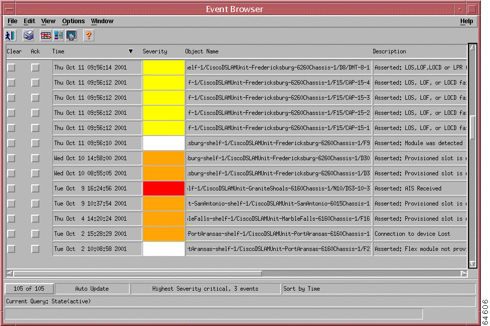
The Event Browser window displays the following information in a table format:
In the Time column, the time and date when the system reports an event
In the Severity column, the level of severity, indicated by the color
In the Object Name column, the name of the object that is affected by the event
In the Description column, a description of the event
Note Use the scroll bars to view all of the columns and all of the alarms.
You can navigate directly from a single event to the affected object to perform detailed configuration activities.
To view events in the Event Browser window, follow these steps:
Step 1 Open the Event Browser window by using one of the following methods:
Choose Event Browser from the Window menu in the CDM Map Viewer window.
Right-click the object on the relevant chassis in the Map Viewer window.
Right-click the object on a map node.
Click the Events icon on the Cisco EMF Launchpad. (See Figure A-2.)
Figure A-2 Events Icon
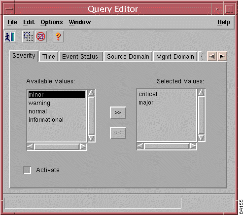
If you click the Events icon, the Event Browser can display events for all of the DSLAMs being managed. Clicking the Events icon opens the Query Editor window (see Figure A-3). Through this window you can specify the severity of the alarms you want to view. (Once the Event Browser is open, you can open the Query Editor again by choosing Query Setup from the Edit menu.)
Figure A-3 Query Editor Window
Step 2 Set your query criteria on the window.
The Query Editor contains the following tabs that you can use to define and refine your alarm search criteria:
Severity
Time
Event Status
Source Domain
Mgmt Domain
User
Event Class
Object Scope
Object Class
Object Attribute Presence
Object Attribute Value
Step 3 Use the >> or << arrows to select or deselect the choices in the Available Values column:
critical
major
minor
warning
normal
informational
Step 4 Always click Activate after you specify the values for the alarms that you want to view.
The Event Browser displays all alarms that match your query criteria.
Note Refer to the Cisco Element Manager Framework User Guide for more detailed information about using
the Query Editor.
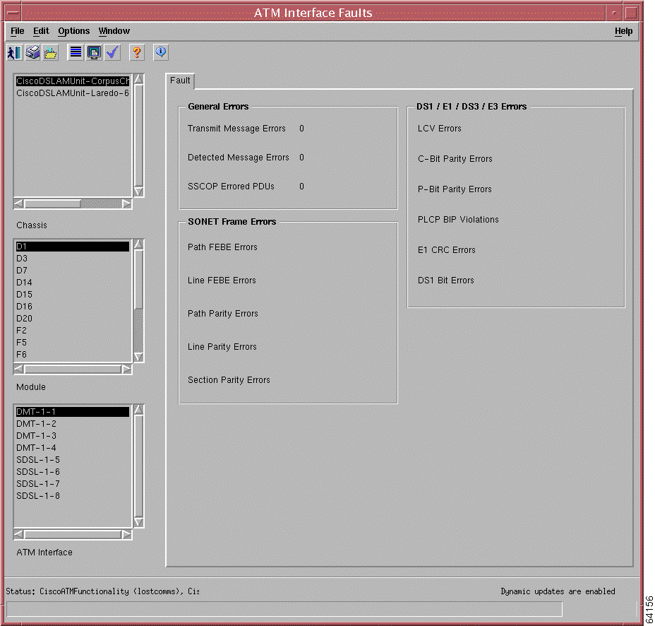
Viewing ATM Interface Faults
You can view faults on ATM interfaces for a specified interface. Complete the following steps to view ATM interface faults:
Step 1 From the Map Viewer window, in the Component Managed view, right-click the chassis object for which you want to view ATM interface faults to access the object menu.
Table A-1 ATM Interface Window—Fault Tab Field Description
Field
Description
General Errors
Transmitted Message Errors
Specifies the number of Incorrect Messages transmitted on the interface. The Incorrect Messages counter reflects any sort of incorrect information in a message.
Detected Message Errors
Identifies the number of Incorrect Messages detected on the interface. The Incorrect Messages counter reflects any sort of incorrect information in a message.
SSCOP Errored PDUs
Calculates the sum of the following errors—Invalid PDUs are defined in SSCOP and consist of PDUs with incorrect length (MAA-ERROR code U); undefined PDU type code; or not 32-bit aligned. PDUs that result in MAA error codes are discarded.
SONET Frame Errors
This area not used.
DS1/E1/DS3/E3 Errors
This area not used.
Determining Alarm Severity
The possible alarm colors and the alarm severity that each color represents is described in Table A-2.
Table A-2 Severity Colors
Color
Severity of Alarms
Red
Critical
Orange
Major
Brown
Moderate
Yellow
Minor
Cyan
Warning
Green
No alarms (normal)
Blue
Card decommissioned or not installed
White
Informational
Dark Green
Preprovisioned
Identifying CDM Alarms
The tables in this section list the alarms that are related to the Cisco Entity Alarm MIB.
Table A-3 describes alarms specific to the Cisco 6100 DSLAM.
Table A-3 Cisco 6100 Alarms
Alarm Severity
Description
Asserted
Cleared
Major
Chassis temperature too high
When the chassis inlet temperature is greater than or equal to 50° C, or when the chassis outlet temperature is greater than or equal to 65° C
When the chassis inlet temperature is less than 50° C, or when the chassis outlet temperature is less than 65° C
Major
Chassis temperature too low
When the chassis inlet temperature is less than or equal to -40° C, or when the chassis outlet temperature is less than or equal to -40°
When the chassis inlet temperature is greater than -40° C, or when the chassis outlet temperature is greater than -40° C
Major
Temperature rating mismatch
When a chassis contains at least one industrial temperature component and at least one commercial temperature component
When all components in a chassis are industrial temperature, or when all components in a chassis are commercial temperature
Major
Fan tray missing or failed
When the fan is missing or has failed
When the fan in functioning properly
Cisco 6015 Alarms
Table A-4 describes alarms specific to the Cisco 6015 DSLAM.
Table A-4 Cisco 6015 Alarms
Alarm Severity
Description
Asserted
Cleared
Major
Chassis temperature too high
When the chassis inlet temperature is greater than or equal to 50° C, or when the chassis outlet temperature is greater than or equal to 65° C
When the chassis inlet temperature is less than 50° C, or when the chassis outlet temperature is less than 65° C
Major
Chassis temperature too low
When the chassis inlet temperature is less than or equal to -40° C, or when the chassis outlet temperature is less than or equal to -40°
When the chassis inlet temperature is greater than -40° C, or when the chassis outlet temperature is greater than -40° C
Major
Temperature rating mismatch
When a chassis contains at least one industrial temperature component and at least one commercial temperature component
When all components in a chassis are industrial temperature, or when all components in a chassis are commercial temperature
Major
Fan Slot not detected or missing
When the agent does not detect the presence of a fan tray in the corresponding fan tray slot
When the agent detects the presence of a fan tray in the corresponding fan tray slot
Major
Multiple fan failures
When more than one fan contained by the fan tray has failed
When all fans contained by the fan tray are functioning properly or when a single fan contained by the fan tray has failed
Minor
Single fan failure
When a single fan contained by the fan tray has failed
When all fans contained by the fan tray are functioning properly or when more than one fan contained by the fan tray has failed
Major
Input voltage out of range
When the input voltage is less than minimum (VAC) or when the input voltage is greater than maximum (VAC)
When the input voltage is greater than or equal to minimum (VAC) and less than or equal to maximum (VAC)
Major
Excessive current
When the product of the input voltage and input current is greater than 1050 W
When the product of the input voltage and the input current is less than or equal to 1050 W
Cisco 6130 Alarms
Table A-4 describes alarms specific to the Cisco 6130 DSLAM.
Table A-5 Cisco 6130 Alarms
Alarm Severity
Description
Asserted
Cleared
Critical
Fan module not detected
When the agent does not detect the presence of a fan module
When the agent detects the presence of a fan module
Critical
Fan tray missing or failed
When the agent does not detect the presence of a fan tray
When the agent detects the presence of a fan tray
Major
Chassis temperature too high
When the chassis inlet temperature is greater than or equal to 50° C, or when the chassis outlet temperature is greater than or equal to 65° C
When the chassis inlet temperature is less than 50° C, or when the chassis outlet temperature is less than 65° C
Major
Chassis temperature too low
When the chassis inlet temperature is less than or equal to -40° C, or when the chassis outlet temperature is less than or equal to -40°
When the chassis inlet temperature is greater than -40° C, or when the chassis outlet temperature is greater than -40° C
Major
Temperature rating mismatch
When a chassis contains at least one industrial temperature component and at least one commercial temperature component
When all components in a chassis are industrial temperature, or when all components in a chassis are commercial temperature
Major
Door open alarm
Alarm generated by equipment wired to connector P4 pin 0 on the I/O card
Alarm cleared by equipment wired to connector P4 pin 0 on the I/O card
Cisco 6160 Alarms
Table A-6 describes alarms specific to the Cisco 6160 DSLAM.
Table A-6 Cisco 6160 Alarms
Alarm Severity
Description
Asserted
Cleared
Major
Chassis temperature too high
When the chassis inlet temperature is greater than or equal to 50° C, or when the chassis outlet temperature is greater than or equal to 65° C
When the chassis inlet temperature is less than 50° C, or when the chassis outlet temperature is less than 65° C
Major
Chassis temperature too low
When the chassis inlet temperature is less than or equal to -40° C, or when the chassis outlet temperature is less than or equal to -40°
When the chassis inlet temperature is greater than -40° C, or when the chassis outlet temperature is greater than -40° C
Major
Temperature rating mismatch
When a chassis contains at least one industrial temperature component and at least one commercial temperature component
When all components in a chassis are industrial temperature, or when all components in a chassis are commercial temperature
Major
Door open alarm
Alarm generated by equipment wired to connector P4 pin 0 on the I/O card
Alarm cleared by equipment wired to connector P4 pin 0 on the I/O card
Major
Station alarm 1
Alarm generated by equipment wired to connector P5 pin 1 on the I/O card
Alarm cleared by equipment wired to connector P5 pin 1 on the I/O card
Major
Station alarm 2
Alarm generated by equipment wired to connector P5 pin 3 on the I/O card
Alarm cleared by equipment wired to connector P5 pin 3 on the I/O card
Major
Station alarm 3
Alarm generated by equipment wired to connector P5 pin 2 on the I/O card
Alarm cleared by equipment wired to connector P5 pin 2 on the I/O card
Major
Fan Slot not detected or missing
When the agent does not detect the presence of a fan tray in the corresponding fan tray slot
When the agent detects the presence of a fan tray in the corresponding fan tray slot
Major
Fan fault
When the fan inside the power supply indicates a fault
When the fan inside the power supply does not indicate a fault
Major
Power supply fault
When the power supply indicates a fault
When the power supply does not indicate a fault
Major
Temperature exceeds limit
When the internal power supply temperature is greater than or equal to 50° C or when the external power supply temperature is greater than or equal to 65° C
When the internal power supply temperature is less than 50°C and the external power supply temperature is less than 65°C
Major
Not detected or missing
When the agent does not detect the presence of a fan tray in the corresponding fan tray slot
When the agent detects the presence of a fan tray in the corresponding fan tray slot
Minor
Single fan failure
When a single fan contained by the fan tray has failed
When all fans contained by the fan tray are functioning properly or when more than one fan contained by the fan tray has failed
Major
Multiple fan failures
When more than one fan contained by the fan tray has failed
When all fans contained by the fan tray are functioning properly or when a single fan contained by the fan tray has failed
Minor
Not detected or missing
When the agent does not detect the presence of a fan tray in the corresponding power supply bay
When the agent detects the presence of a fan tray in the corresponding power supply bay
Cisco 6260 Alarms
Table A-7 describes alarms specific to the Cisco 6260 DSLAM.
Table A-7 Cisco 6260 Alarms
Alarm Severity
Description
Asserted
Cleared
Major
Chassis temperature too high
When the chassis inlet temperature is greater than or equal to 50° C, or when the chassis outlet temperature is greater than or equal to 65° C
When the chassis inlet temperature is less than 50° C, or when the chassis outlet temperature is less than 65° C
Major
Chassis temperature too low
When the chassis inlet temperature is less than or equal to -40° C, or when the chassis outlet temperature is less than or equal to -40° C
When the chassis inlet temperature is greater than -40° C, or when the chassis outlet temperature is greater than -40° C
Major
Temperature rating mismatch
When a chassis contains at least one industrial temperature component and at least one commercial temperature component
When all components in a chassis are industrial temperature, or when all components in a chassis are commercial temperature
Major
Door open alarm
Alarm generated by equipment wired to connector P4 pin 0 on the I/O card
Alarm cleared by equipment wired to connector P4 pin 0 on the I/O card
Major
Station alarm 1
Alarm generated by equipment wired to connector P5 pin 1 on the I/O card
Alarm cleared by equipment wired to connector P5 pin 1 on the I/O card
Major
Station alarm 2
Alarm generated by equipment wired to connector P5 pin 3 on the I/O card
Alarm cleared by equipment wired to connector P5 pin 3 on the I/O card
Major
Station alarm 3
Alarm generated by equipment wired to connector P5 pin 2 on the I/O card
Alarm cleared by equipment wired to connector P5 pin 2 on the I/O card
Major
Fan Slot not detected or missing
When the agent does not detect the presence of a fan tray in the corresponding fan tray slot
When the agent detects the presence of a fan tray in the corresponding fan tray slot
Major
Input voltage out of range
When the input voltage is less than minimum (VAC) or when the input voltage is greater than maximum (VAC)
When the input voltage is greater than or equal to minimum (VAC) and less than or equal to maximum (VAC)
Major
Excessive current
When the product of the input voltage and input current is greater than 1050 W
When the product of the input voltage and the input current is less than or equal to 1050 W
Major
Fan voltage out of range
When the fan voltage is less than minimum VDC or when the fan voltage is greater than maximum VDC
When the fan voltage is greater than or equal to minimum VDC and less than or equal to maximum VDC
Major
Power supply fault
When the power supply indicates a fault
When the power supply does not indicate a fault
Major
Temperature exceeds limit
When the internal power supply temperature is greater than or equal to 50°C, or when the external power supply temperature is greater than or equal to 65°C
When the internal power supply temperature is less than 50°C and the external power supply temperature is less than 65°C
Minor
Single fan failure
When a single fan contained by the fan tray has failed
When all fans contained by the fan tray are functioning properly or when more than one fan contained by the fan tray has failed
Major
Multiple fan failures
When more than one fan contained by the fan tray has failed
When all fans contained by the fan tray are functioning properly or when a single fan contained by the fan tray has failed
Minor
Fan tray not detected or missing
When the agent does not detect the presence of a fan tray in the corresponding power supply bay
When the agent detects the presence of a fan tray in the corresponding power supply bay
ADSL-CAP Alarms
Table A-8 describes alarms specific to ADSL-CAP cards.
Table A-8 ADSL-CAP Alarms
Alarm Severity
Description
Asserted
Cleared
Minor
SNR margin below config value
When the actual SNR margin is less than the SNR margin threshold
When the actual SNR margin is greater than or equal to the SNR margin threshold
Minor
Upstream rate below minimum rate
When the actual upstream rate is less than the provisioned minimum upstream rate
When the actual upstream rate is greater than or equal to the provisioned minimum upstream rate
Minor
Downstream rate below minimum rate
When the actual downstream rate is less than the provisioned minimum downstream rate
When the actual downstream rate is greater than or equal to the provisioned minimum downstream rate
Minor
CPE signature below config value
When the actual CPE signature is less than the provisioned CPE signature
When the actual CPE signature is greater than or equal to the provisioned CPE signature
Minor
LOS, LOF, or LOCD failure
When the ADSL CAP line interface experiences one of the following defects: LOS, LOF, LOCD
When the ADSL CAP line interface experiences none of the following defects: LOS, LOF, LOCD
ADSL-DMT Alarms
Table A-9 describes alarms specific to ADSL-DMT cards.
Table A-9 ADSL-DMT Alarms
Alarm Severity
Description
Asserted
Cleared
Minor
ATU-C port failure
When the ATU-C can not communicate with the chip set implementing the port
When the ATU-C can communicate with the chip set implementing the port
Minor
Upstream rate below minimum rate
When the interleaved channel's actual upstream rate is less than the provisioned minimum upstream rate or when the fast channel's actual upstream rate is less than the provisioned minimum upstream rate
When the both the interleaved channel's actual upstream rate is greater than or equal to the provisioned minimum upstream rate, and the fast channel's actual upstream rate is greater than or equal to the provisioned minimum upstream rate
Minor
Downstream rate below minimum rate
When the interleaved channel's actual downstream rate is less than the provisioned minimum downstream rate or when the fast channel's actual downstream rate is less than the provisioned minimum downstream rate
When the both the interleaved channel's actual downstream rate is greater than or equal to the provisioned minimum downstream rate, and the fast channel's actual downstream rate is greater than or equal to the provisioned minimum downstream rate
Minor
LOS, LOF, LOCD or LPR failure
When the ADSL DMT line interface experiences one of the following defects: LOS, LOF, LOCD, or far-end LPR
When the ADSL DMT line interface experiences none of the following defects: LOS, LOF, LOCD, or far-end LPR
SDSL Alarms
Table A-10 describes alarms specific to SDSL cards.
Table A-10 SDSL Alarms
Alarm Severity
Description
Asserted
Cleared
Minor
STUC port failure
When the line is configured to be administratively up, but it is operationally down; in other words, there is no physical layer connectivity with the CPE
When the line has physical layer connectivity with the CPE Or when the line is administratively down
Minor
SNR margin below config value
When the actual SNR margin is less than the SNR margin threshold
When the actual SNR margin is greater than or equal to the SNR margin threshold
Minor
Bit rate below minimum rate
When the actual rate is less than the provisioned minimum rate
When the actual rate is greater than or equal to the provisioned minimum rate
G. SHDSL Alarms
Table A-11 describes alarms specific to G.SHDSL cards.
Table A-11 SHDSL Alarms
Alarm Severity
Description
Asserted
Cleared
Minor
STUC port failure
When the line is configured to be administratively up, but it is operationally down; in other words, when there is no physical layer connectivity with the CPE
When the line has physical layer connectivity with the CPE or when the line is administratively down
Minor
SNR margin below config value
When the actual SNR margin is less than the SNR margin threshold
When the actual SNR margin is greater than or equal to the SNR margin threshold
Minor
Bit rate below minimum rate
When the actual rate is less than the provisioned minimum rate.
When the actual rate is greater than or equal to the provisioned minimum rate.
Minor
Oversubscription
When the total provisioned bit rates on odd or even ports are less than 5 Mbps.
When the total provisioned bit rates on odd or even ports are greater than or equal to 5 Mbps
DS3/DS3 NI-2 Alarms
Table A-12 describes alarms specific to DS3/DS3 NI-2 configurations.
Table A-12 Alarms Specific to DS3/DS3 NI2 Configurations
Alarm Severity
Description
Asserted
Cleared
Critical
RAI Received
When the DS3 interface experiences an RAI defect
When the DS3 interface is not experiencing an RAI defect
Critical
Yellow Alarm Received
When the DS3 interface experiences a yellow alarm
When the DS3 interface is not experiencing a yellow alarm
Critical
AIS Received
When the DS3 interface experiences an AIS defect
When the DS3 interface is not experiencing an AIS defect
Critical
OOF Received
When the DS3 interface experiences an OOF defect
When the DS3 interface is not experiencing an OOF defect
Critical
LOS Detected
When the DS3 interface experiences an LOS defect
When the DS3 interface is not experiencing an LOS defect
Critical
PLCP LOF Detected
When the DS3 interface experiences a PLCP LOF defect
When the DS3 interface is not experiencing a PLCP LOF defect
Critical
FERF Received
When the DS3 interface experiences an FERF defect
When the DS3 interface is not experiencing an FERF defect
Critical
FEBE Received
When the DS3 interface experiences an FEBE defect
When the DS3 interface is not experiencing an FEBE defect
Critical
RAI Received
When the DS3 interface experiences an RAI defect
When the DS3 interface is not experiencing an RAI defect
Critical
Yellow Alarm Received
When the DS3 interface experiences a yellow alarm
When the DS3 interface is not experiencing a yellow alarm
Critical
AIS Received
When the DS3 interface experiences an AIS defect
When the DS3 interface is not experiencing an AIS defect
Critical
OOF Received
When the DS3 interface experiences an OOF defect
When the DS3 interface is not experiencing an OOF defect
Critical
LOS Detected
When the DS3 interface experiences an LOS defect
When the DS3 interface is not experiencing an LOS defect
Critical
PLCP LOF Detected
When the DS3 interface experiences an PLCP LOF defect
When the DS3 interface is not experiencing an PLCP LOF defect
Critical
Subtend Port Configured as Trunk
Subtend port configured as trunk
Subtend port not configured as trunk
DS3/T1E1 NI-2 Alarms
Table A-13 describes alarms specific to DS3/T1E1 NI-2 configurations.
Table A-13 Alarms Specific to DS3/T1E1 NI2 Configurations
Alarm Severity
Description
Asserted
Cleared
Critical
Loss of Cell Delineation
When the DS3 interface experiences an LOCD defect
When the DS3 interface is not experiencing an LOCD defect
Critical
Loss of Cell Delineation
When the DS3 interface experiences an LOCD defect
When the DS3 interface is not experiencing an LOCD defect
E1 IMA Group Alarms
Table A-14 describes alarms specific to E1 IMA groups.
Table A-14 E1 IMA Group Alarms
Alarm Severity
Description
Asserted
Cleared
Critical
Configuration Abort
When the FE tries to use unacceptable configuration parameters
When the FE tries to use acceptable configuration parameters
Critical
Configuration Abort - FE
When the FE reports unacceptable configuration parameters
When the FE reports acceptable configuration parameters
Critical
Insufficient Links
When less than P(Tx) transmit or P(Rx) receive links are active
When at least P(Tx) transmit or P(Rx) receive links are active
Critical
Insufficient Links - FE
When the FE reports that fewer than P(Tx) transmit or P(Rx) receive links are active
When the FE reports that at least P(Tx) transmit or P(Rx) receive links are active
Critical
Blocked - FE
When the FE reports that it is blocked
When the FE reports that it is not blocked
Critical
Timing Mismatch
When the FE transmit clock mode is different from the NE transmit clock mode
When the FE transmit clock mode is the same as the NE transmit clock mode
E1 IMA Link Alarms
Table A-15 describes alarms specific to E1 IMA Links.
Table A-15 E1 IMA Link Alarms
Alarm Severity
Description
Asserted
Cleared
Critical
Alarm Indication Signal
When the IMA interface experiences an AIS defect
When the IMA interface is not experiencing an AIS defect
Critical
Remote Alarm Indication
When the IMA interface experiences an RAI defect
When the IMA interface is not experiencing a RAI defect
Critical
Loss of Cell Delineation
When the IMA interface experiences an LOCD defect
When the IMA interface is not experiencing an LOCD defect
Critical
Loss of IMA Frame
Persistence of a LIF defect at the NE
No persistence of an LIF defect at the NE
Critical
Link Out of Delay Sync
Persistence of a LODS defect at the NE
No persistence of an LODS defect at the NE
Critical
Tx Link Misconnected
When the Tx link is detected as misconnected. This is reported when the IMA unit has determined that the Tx link is not connected to the same FE IMA unit as the other Tx links in the group. The detection is implementation-specific.
When the Tx link is not detected as misconnected
Critical
Rx Link Misconnected
When the Rx link is detected as misconnected. This is reported when the IMA unit has determined that the Rx link is not connected to the same FE IMA unit as the other Rx links in the group. The detection is implementation-specific.
When the Rx link is not detected as misconnected
Critical
Rx Fault
Implementation-specific Rx fault declared at the NE
Implementation specific Rx fault not declared at the NE
Critical
Tx Fault
Implementation-specific Tx fault declared at the NE
Implementation specific Tx fault not declared at the NE
Critical
Tx Link Unusable - FE
When the FE reports Tx-Unusable
When the FE does not report Tx-Unusable
Critical
Rx Link Unusable - FE
When the FE reports Rx-Unusable
When the FE does not report Rx-Unusable
T1 IMA Group Alarms
Table A-16 describes alarms specific to T1 IMA Groups.
Table A-16 T1 IMA Group Alarms
Alarm Severity
Description
Asserted
Cleared
Critical
Configuration Abort
When the FE tries to use unacceptable configuration parameters
When the FE tries to use acceptable configuration parameters
Critical
Configuration Abort - FE
When the FE reports unacceptable configuration parameters
When the FE reports acceptable configuration parameters
Critical
Insufficient Links
When less than P(Tx) transmit or P(Rx) receive links are Active
When at least P(Tx) transmit or P(Rx) receive links are Active
Critical
Insufficient Links - FE
When the FE reports that less than P(Tx) transmit or P(Rx) receive links are active
When the FE reports that at least P(Tx) transmit or P(Rx) receive links are active
Critical
Blocked - FE
When the FE reports that it is blocked
When the FE reports that it is not blocked
Critical
Timing Mismatch
When the FE transmit clock mode is different than the NE transmit clock mode
When the FE transmit clock mode is the same as the NE transmit clock mode
T1 IMA Link Alarms
Table A-17 describes alarms specific to T1 IMA Links.
Table A-17 T1 IMA Link Alarms
Alarm Severity
Description
Asserted
Cleared
Critical
Alarm Indication Signal
When the IMA interface experiences an AIS defect
When the IMA interface is not experiencing an AIS defect
Critical
Remote Alarm Indication
When the IMA interface experiences an RAI defect
When the IMA interface is not experiencing an RAI defect
Critical
Loss of Cell Delineation
When the IMA interface experiences an LOCD defect
When the IMA interface is not experiencing an LOCD defect
Critical
Loss of IMA Frame
Persistence of an LIF defect at the NE
No persistence of an LIF defect at the NE
Critical
Link Out of Delay Sync
Persistence of an LODS defect at the NE
No persistence of an LODS defect at theNE
Critical
Tx Link Misconnected
When the Tx link is detected as mis-connected. This is reported when the IMA unit has determined that the Tx link is not connected to the same FE IMA unit as the other Tx links in the group. The detection is implementation-specific.
When the Tx link is not detected as misconnected
Critical
Rx Link Misconnected
When the Rx link is detected as misconnected. This is reported when the IMA unit has determined that the Rx link is not connected to the same FE IMA unit as the other Rx links in the group. The detection is implementation-specific.
When the Rx link is not detected as misconnected
Critical
Rx Fault
Implementation-specific Rx fault declared at the NE
Implementation specific Rx fault not declared at the NE
Critical
Tx Fault
Implementation-specific Tx fault declared at the NE
Implementation specific Tx fault not declared at the NE
Critical
Tx Link Unusable - FE
When the FE reports Tx-Unusable
When the FE does not report Tx-Unusable
Critical
Rx Link Unusable - FE
When the FE reports Rx-Unusable
When the FE does not report Rx-Unusable
OC-3 Alarms
Table A-18 describes alarms specific to OC-3 cards.
Table A-18 OC3 Alarms
Alarm Severity
Description
Asserted
Cleared
Critical
Loss of Cell Delineation
When the ATM interface associated with the SONET/SDH interface experiences an LOCD defect
When the ATM interface associated with the SONET/SDH interface is not experiencing LOCD defect
Minor
Signal Label Mismatch
When the SONET/SDH path experiences a signal mismatch defect
When the SONET/SDH path is not experiencing a signal mismatch defect
Critical
Path RDI Received
When the SONET/SDH path experiences a RDI defect
When the SONET/SDH path is not experiencing an RDI defect
Critical
Path AIS Received
When the SONET/SDH path experiences an AIS defect
When the SONET/SDH path is not experiencing an AIS defect
Critical
Loss of Pointer
When the SONET/SDH path experiences an LOP defect
When the SONET/SDH path is not experiencing an LOP defect
Critical
Line RDI
When the SONET/SDH line experiences an RDI defect
When the SONET/SDH line is not experiencing an RDI defect
Critical
Line AIS Received
When the SONET/SDH line experiences an AIS defect
When the SONET/SDH line is not experiencing an AIS defect
Critical
Loss of Frame
When the SONET/SDH section experiences an LOF defect
When the SONET/SDH section is not experiencing an LOF defect
Critical
Loss of Signal
When the SONET/SDH section experiences an LOS defect
When the SONET/SDH section is not experiencing an LOS defect