|
|

Table Of Contents
Cisco Access Router Manager Chassis
Physical Interfaces and Logical Interface Technologies
Concepts
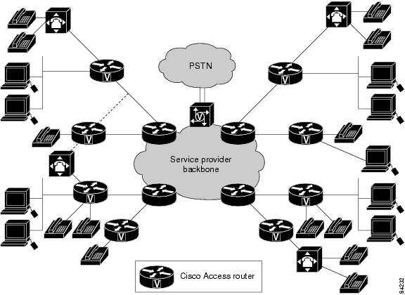
The Cisco Access Router Manager routers are a multifunctioning platform that combines dial access, routing and LAN-to-LAN services, and multiservice integration of voice, video and data in the same device.
The Cisco Access Router Manager supports the following modular access routers:
•
Cisco 2610, 2610-DC, 2610-RPS, 2610XM, 2610XM-DC, and 2610XM-RPS
•
•
•
•
•
•
•
•
•
•
•
•
•
The following figure shows a typical Cisco Access Router Manager deployment.
Figure 1-1 Typical Cisco Access Router Manager Deployment
The Concepts chapter describes EM concepts and covers the following information:
•
EM Documentation Set
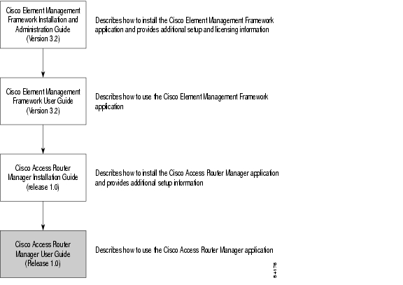
This guide is one part of the Cisco Access Router Manager EM documentation set. The following figure displays all of the guides in the EM documentation set and details the contents of each.
Figure 1-2 EM Documentation Set
The guides identified in the preceding figure are available from Cisco Systems. For further information on obtaining Cisco documentation, see the "Obtaining Documentation" section on page -xvii.
Hardware Support
This section contains the following information:
•
•
Cisco Access Router Manager Chassis
The following table lists the Cisco Access Router Manager routers that are supported, including the different power supply options for each.
In the preceding table, "Yes" indicates that the power supply type or option is supported by the router and "N/A" indicates that the power supply type or option is supported not by the router.
The Cisco 2600 series routers which the Cisco Access Router Manager supports accommodate one network module, one internal flash SIMM slot, and two internal DRAM slots. The Cisco 2600 series consists of modular multiservice access routers which provide flexible LAN and WAN configurations, multiple security options, and a range of high performance processors. The latest additions to the Cisco 2600 series of modular routers include the Cisco 2600XM models. These new models deliver extended performance, higher density, enhanced security performance, and increased concurrent application support.
The following table describes the Cisco 2600 series routers supported. Because more than one router may support similar features, routers are grouped and varying support is indicated within the table where applicable.
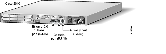
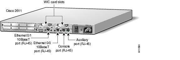
The following figures provide examples of the Cisco 2600 series chassis.
Figure 1-3 Cisco 2610 Chassis
Figure 1-4 Cisco 2610XM Chassis Example
Figure 1-5 Cisco 2611 Chassis
Figure 1-6 Cisco 2611XM Chassis Example
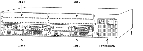
Figure 1-7 Cisco 2612 Chassis
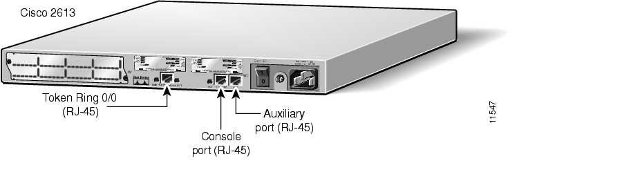
Figure 1-8 Cisco 2613 Chassis
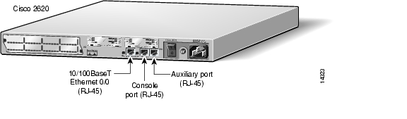
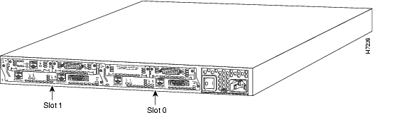
Figure 1-9 Cisco 2620 Chassis
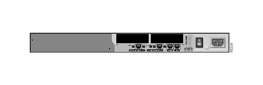
Figure 1-10 Cisco 2620XM Chassis Example
Figure 1-11 Cisco 2621 Chassis
Figure 1-12 Cisco 2621XM Chassis Example
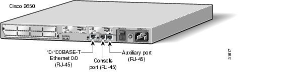
Figure 1-13 Cisco 2650 Chassis
Figure 1-14 Cisco 2650XM Chassis Example
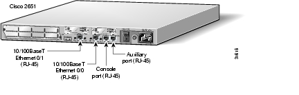
Figure 1-15 Cisco 2651 Chassis
Figure 1-16 Cisco 2651XM Chassis Example
The following table outlines the Cisco 3000 series routers supported.
The following figures provide examples of the Cisco 3000 series chassis.
Figure 1-17 Cisco 3620 Chassis
Figure 1-18 Cisco 3640 Chassis Example
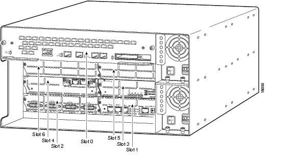
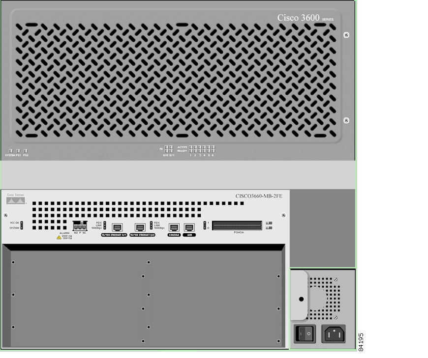
Figure 1-19 Cisco 3661/3662 Chassis
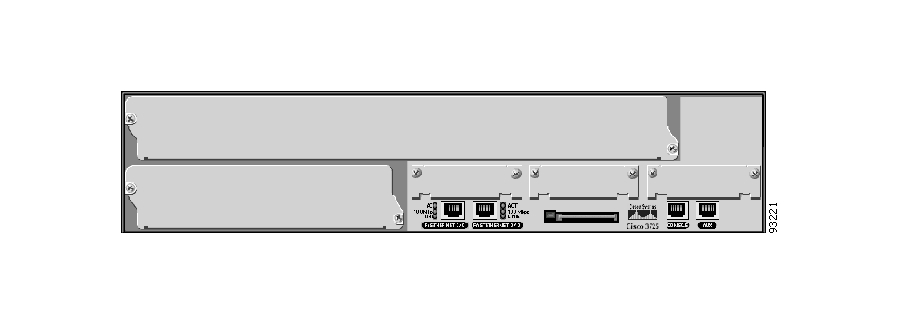
Figure 1-20 Cisco 3725 Chassis Example
Figure 1-21 Cisco 3745 Chassis Example
The Cisco 3660 routers provide online insertion and removal (OIR) capabilities for "like-to-like" network modules. OIR is restricted to "like-to-like" network modules due to the amount of available input/output (I/O) memory. If, for example, I/O memory is low, there is the risk of running out of memory if a high I/O memory module is inserted where a low I/O memory module once was. To help avoid memory issues, the Cisco 3600 routers reserve 750 KBs of memory per each empty network module slot at boot time.
Individual WICs and VICs, however, do not support OIR. Only entire network modules are hot swappable.
The Cisco 3700 Application Service Routers enable dramatically higher levels of application and service integration in enterprise branch offices. With on-board LAN/WAN connectivity, new high density service modules, and support for multiple AIMs, the Cisco 3700 series delivers new levels of branch office service density in a compact form factor.
The Cisco 3700 series offers a single, integrated platform that combines flexible routing and low density switching. The Cisco 3700 series can deliver internal inline power for the EtherSwitch ports, thus delivering a compelling single platform Branch Office IP Telephony and Voice Gateway solution which enables flexible, incremental, and scalable migration to a converged branch office network.
Supporting Modules
The EM supports the following types of supporting modules within a chassis. Some modules only apply to certain chassis types.
•
•
•
The EM does not provide for management of supporting modules such as fan trays. Power supply modules are available for management via the EM FCAPS windows.
Modules
The EM supports the following types of modules:
•
•
•
•
The supported Cisco Access Router Manager routers described within this section can accommodate between one and six network modules, depending on the chassis. Not all of the chassis supported, however, can accommodate every network module. The following table maps the supported chassis to the compatible network modules.
In the preceding table, "Yes" indicates that the network module is compatible with the router and "N/A" indicates that the network module is not compatible with the router.
The supported network modules described within this section can accommodate between one and four interface cards (e.g., WICs, VICs, VWICs), depending on the module. Not all of the network modules supported, however, can accommodate interface cards. The following table maps the voice/fax network modules to the compatible WIC, VIC, and VWIC interface cards.
In the preceding table, "Yes" indicates that the network module is compatible with the router and "N/A" indicates that the network module is not compatible with the router.
Cisco EMF Software Features
Cisco EMF provides a flexible framework which supports a variety of EMs, making it possible to manage multiple device types within a given network on a single system. Common network management functionality provides for complete management of the logical and physical components of the network. Using a solid base, Cisco EMF provides vital core functionality which allows for optimal network management when combined with EMs. Features include the following:
•
•
•
•
•
•
•
•
•
•
•
•
For further information on Cisco EMF and the tools it provides, see the following items:
•
The Cisco Element Management Framework User Guide Release 3.2 at the following URL:
http://www.cisco.com/en/US/partner/products/sw/netmgtsw/ps829/products_user_guide_book09186a00800ffd02.html•
EM Software Features
Installed with Cisco EMF, the EM allows for precise management of the device(s) it supports through custom GUI windows and modeling behavior. Invoked from the Cisco EMF Map Viewer application, the EM provides Fault, Configuration, Accounting, Performance, and Security (FCAPS) windows on chassis, module, interface, and connection levels as applicable. These windows provide the features which compliment the Cisco EMF capabilities to provide for complete, efficient network management.
Specifically, the Cisco Access Router Manager supports the related routers, as well as various modules including ATM, Ethernet, SONET, and IP modules. Element management capabilities for these items are provided in windows and wizards, eliminating the need for operators to have detailed Cisco IOS software and SNMP-based knowledge for individual interface or system parameter commands.
The following features highlight the capabilities of the EM:
•
•
•
–
–
•
•
•
–
•
•
•
•
EM Objects and Interfaces
The EM manages both physical and logical objects as follows:
•
•
Fault, Configuration, Accounting, Performance, and Security (FCAPS) windows are accessible on both physical and logical EM objects, in the form of FCAPS menu options that appear when you right-click on any object in the EM. FCAPS functionality provides a complete management interface to features of the router.
The EM uses Telecom Graphics Objects (TGO) in the Map Viewer application. TGO is a TeleManagement Forum (TMF) sponsored initiative to provide standard graphical representations for network topology maps.
A TGO displays additional information icons on top of the existing object icons displayed in Map Viewer. The additional icons indicate a variety of information (for example, information on the state of the object or event status information). The following figure provides an example of a TGO.
Figure 1-22 Sample Telecom Graphical Object
An object is a representation of a network element. For example, the object could be a node, a shelf, a shelf item, or a link. Each object shown in the right window provides pictorial cues which provide information about its associated network element. The information can be structural information; for example, a network element name or state and event information such as "out of service."
Each object can display the following information about its associated network element:
•
•
•
–
–
–
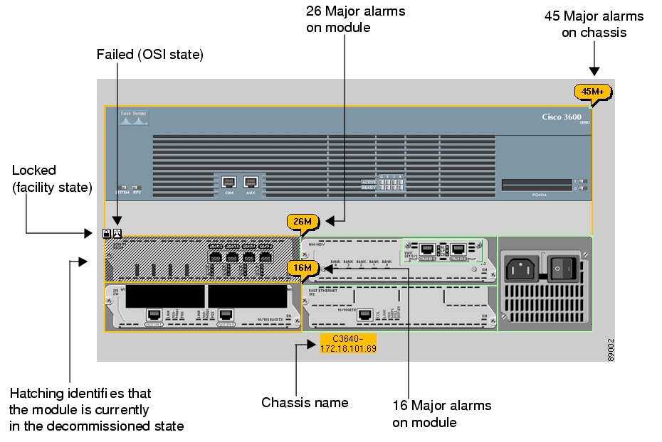
The following figure shows an example of a chassis map displaying a few of the TGO icons that could appear.
Figure 1-23 Sample Chassis Showing Telecom Graphical Objects
Note
This section covers the following areas:
•
Physical Objects
The following table lists all physical objects created in the EM and the management functions that can be performed on each object.
Table 1-10 Physical Objects and Management Functions
Chassis—The hardware frame of the Cisco Access Router Manager router, which houses all subchassis objects (modules)
Fault
Configuration
AccountingProcessor Cards—The Cisco Access Router Manager routers support router processor cards.
Fault
Configuration
Accounting
PerformanceModules—Modules may be either network modules or voice interface cards. There are various types of modules within a chassis (for example, ATM, Ethernet, and Generic). Each of these modules support a given number of physical interfaces (ports).
Fault
Configuration
Accounting
PerformancePhysical Interfaces—Each module (interface or port adapter) has at least one, if not multiple, physical interfaces (ports). The type of physical interface is equivalent to the type of module the interface resides on. Each different physical interface can support multiple technologies (for details, see the "Physical Interfaces and Logical Interface Technologies" section). The module type determines what technologies reside on the interfaces.
Fault
Configuration
PerformanceSupporting Modules—Additional subchassis cards and modules, including power supply module(s), processor module(s), and fan tray modules. The EM supports the management functions to the right on power supply and processor modules only.
Fault
Configuration
Performance
Accounting
The physical objects and interfaces in the preceding table are organized as follows:
•
•
For further details on hierarchies within Cisco EMF and the EM, see the "Views" section.
Tip
Physical Interfaces and Logical Interface Technologies
Physical interfaces and logical interface technologies are modeled as objects below a parent module. As mentioned before, the type of module characterizes the type of interface. Interface types further break down into two categories, physical interfaces and logical interface technologies.
Physical interfaces are the ports which exist on line cards. This EM supports the following physical interfaces:
•
•
The EM handles both SDH and SONET in the same manner. The routers support both SDH and SONET. For a comparison chart of SONET and SDH speeds, see "SONET/SDH Conversion Chart."
Logical interface technologies represent the communication between two network devices. Logical interface technologies allow for virtual connections, such as PVCs and SPVCs.
The Cisco Access Router Manager currently does not display or support the management of virtual connections, such as PVCs or SPVCs. This EM, however, supports the following logical interface technologies:
•
•
Physical interfaces and logical interface technologies are classified as "interfaces" within this EM, and, therefore, are referred to as such within this guide. Keep in mind the differences previously described as you manage the interfaces within your network.
Tip
The following table outlines each interface type and the applicable physical and logical interface technologies supported. Also included are the different FCAPS service windows that are applicable to each physical and logical interface technology. For example, if you want to configure an ATM interface type, look in the table under ATM, and you will notice that three physical interface and logical interface technologies apply: ATM, SONET, and IP. This means that to fully configure an ATM over SONET interface, for example, you should open and update the appropriate fields in all the physical and logical configuration windows to completely configure a SONET interface which supports ATM technology. Note that the shaded areas denote logical interface technologies.
Table 1-11 Physical Interfaces, Related Technologies and Windows
Although not technology-specific, physical or logical, generic support is available through Configuration, Status, and Performance windows for each of the interface types in the preceding table.
Views
Views are accessible by clicking the Viewer icon on the Cisco EMF launchpad. These views appear in the frame at the left of the window when you open the Map Viewer window (see the following figure for an example).
Views model hierarchical relationships between objects, both physical and logical. Objects are organized into different views and can exist in multiple views simultaneously by reference. Each object can have a number of parent and child objects. You can access EM objects by navigating through one of the views to find specific objects by expanding the text. Click on the plus sign (+) next to any object to expand the view. A minus sign (-) next to an object indicates there are no more levels to expand; you may, however, click on a minus sign (-) to collapse the view to the level of the specific object as necessary. Each view represents a different way of containing and grouping objects.
The EM adds specific views to the standard views supplied by Cisco EMF. The standard Cisco EMF views are the Physical and Network views.
Note
Figure 1-24 EM Views
The number in parenthesis next to a view indicates how many top-level objects are contained within the view.
The Views section covers the following areas:
•
You may or may not see all of these views using this EM (exceptions noted). These views all exist within EMs, however they are not all implemented. If multiple EMs are co-resident, the applicable views are displayed.
As the following sections detail, the views you will use to perform the majority of the EM capabilities are the Physical and Component Managed views. Both are similar in structure and allow you to initiate the EM windows. However it is recommended that you use the Physical view to perform most management functions within the EM. The Physical view provides a graphical representation of the chassis that the Component Managed view does not. It should, however, be noted that you must use the Component Managed view to see representative ATM connection objects within the EM as ATM connection objects are not available through the Physical view.
Component Managed View
The Component Managed view displays all objects within the Cisco EMF system. For example, say you have two different EMs installed in Cisco EMF: EM A and EM B. Information for both the EM A and EM B display within the Component Managed view. Additionally, the Component Managed view also displays ATM connections such as PVCs and SPVCs. Connection objects are not visible in any other view. However, it is not recommended to work within this view unless you have multiple EMs installed.
The Component Managed view and Physical view have the same basic hierarchy structure, as shown in the following figure. Note that the Physical view does not display logical ATM connections like the Component Managed view does.
Figure 1-25 Hierarchy of Component Managed and Physical Views
Note
Figure 1-26 shows an example of the menu structure of the Component Managed view.
Figure 1-26 Component Managed Menu Structure Example
Cisco Access Router Manager does not support ATM connection management, therefore logical ATM connection objects associated with the supported devices are not apparent in the Component Managed view.
Layer 3 QoS View
The Layer 3 QoS view displays only Layer 3 QoS objects within the EM, such as the following:
•
•
•
You can work within this view to create and configure Access Lists or CAR or WRED objects by accessing the respective EM menus.
This version of the EM does not provide Layer 3 QoS support. Neither the Layer 3 QoS view nor the respective menus are applicable.
Network View
This view displays all network devices within their relevant networks and subnets. The auto-discovery system of Cisco EMF uses this view to determine which devices exist on the system so that it does not try to discover the same device multiple times. For details on auto-discovery, see the "Automatically Discovering Chassis" section on page 3-2.
Physical View
Objects in the Physical view are ordered according to their relative physical location. The Physical view defines physical containment relationships, meaning that each object is defined according to which object it is contained within. For example, a site is located under the Physical view; a chassis is contained under a site; and sub modules and supporting modules are contained within a chassis.
See Figure 1-25 for an overview of the structure of the Physical view.
The Physical view also provides chassis maps, which are graphical representations of the chassis and its contents. You can access management menus on objects within chassis maps. To display a chassis map, simply click on the chassis object for the router you wish to view. Logical connection objects are not apparent under the Physical view.
Figure 1-27 Physical View Chassis Map
Figure 1-26 shows an example of the menu structure of the Physical view.
Figure 1-28 Physical View Menu Structure Example
RME View
All objects managed by the RME server display beneath the RME view. Objects are organized by RME server objects.
Note
http://www.cisco.com/en/US/products/sw/ciscowork/ps2073/products_user_guide_book09186a00800ca43b.html
Self Management View
This view allows you to monitor network elements which are part of the Cisco EMF system. The Self Management view is non-propagating.
Object States
Object states reflect the life cycle of an object. Whatever stage the object is in at any given time displays in the state type. The state of an object can change frequently, depending upon what actions take place on the object. All objects within the EM are in a specific state which appears at the bottom left corner of each FCAPS window. The following figure highlights an object's state.
Figure 1-29 EM Object States
The two most common object states are Normal and Decommissioned. For example, when you deploy a module in the EM, the initial state of the module is decommissioned. You can then commission the module to begin active management. (For instruction on how to commission a module, see the "Commissioning Modules" section on page 3-36 or on page 5-19.) When you commission the module, it passes through two transitory states: discovery, then commissioning. The commissioning process determines which state to move the object into (typically Normal). This example reflects the basic process of deploying and commissioning an object.
Certain states ripple down to objects below. For example, if you decommission a chassis, all subchassis objects also decommission. If you enable performance logging on a module, all interfaces under the module also enable.
By default, FCAPS windows refresh at a rate dependent upon the type of window. For example, inventory windows refresh at a lower rate than performance windows. The average refresh rate is every 30 seconds.
The following sections describe the possible states that an object may be in and provides a description of these states.
Normal State
The normal state indicates that an object is operational. When an object enters the normal state, the EM performs heartbeat polling on objects at varying intervals to determine their presence and current state. For instance, chassis presence polling occurs every minute while module and interface presence polling occurs every five minutes.
Decommissioned State
The decommissioned state indicates that an object is not managed. When you manually deploy an object, the object is normally put into the decommissioned state.
Tip
The following actions occur on a decommissioned object:
•
•
Decommission buttons are located in Chassis, Module, Interface, and Connection Configuration windows. When you decommission an object, any children of that object also change their state to decommissioned. For example, if you decommission a chassis, all objects within that chassis (modules, interfaces, and connections) also decommission. If you decommission a module, all interfaces and connections on that module decommission, and so on.
Errored
If the operational status of a module goes down, it moves into the errored state. In the errored state, performance polling (if active) stops; however, heartbeat polling (which polls an object every 5 minutes to verify its existence and current state) continues until the device responds positively to a heartbeat request. When the module responds positively to heartbeat requests, it moves back into the previously held state.
Performance Logging On
Enabling performance logging on for an object in the Normal state moves the object into the performance logging on state. This means that performance data collection for the object begins and is available for review in the Cisco EMF Performance Manager window. Regardless of whether performance logging is on or off for a particular object, current performance data is available in the EM Performance windows as Chapter 9, "Performance", describes.
You can enable performance logging on a global scale or on an individual object basis. Enabling global performance logging puts all subchassis objects into a performance logging on state.
Performance logging occurs every 15 minutes. This means that when you enable performance logging or global performance logging initially on an object, at least one 15-minute increment must pass before data displays in the Performance Manager.
Heartbeat polling occurs on objects in the performance logging on state. If the object moves into the errored state, it returns to the performance logging on state when the error is rectified. For example, if a module is in the performance logging on state and it goes down, it moves into the errored state. When heartbeat polling finds that the module is back up, it restores the module to the performance logging on state.
Lost Comms
The lost comms (lost communications) state indicates that the object is not responding to heartbeat polling. The EM can apply this state to a chassis, module, or interface. When an object is in the lost comms state, heartbeat polling occurs on the object. When the object responds to heartbeat polling, it moves out of the lost comms state. For example, say an ATM module in the EM was predeployed. When you perform device synchronization (commissioning a chassis), the ATM module is not yet physically present in the hardware. In this situation, the EM places the ATM module into the lost comms state, where it continues to poll for the presence of the module. When the ATM module is inserted into the chassis, the EM detects its presence and moves the module out of the lost comms state and into a respective state (typically normal).
Lost Comms No Poll
The lost comms (lost communications) no poll state occurs when the router is not contactable. When the EM loses connectivity with a device, the representative chassis object remains in the lost comms state so that heartbeat polling continues on the chassis. However, all modules and interfaces within that chassis move into a lost comms no poll state. There is no point in polling modules and interfaces within a device that is not contactable. If the connection with the device is down, all modules and interfaces will be down. When the device becomes contactable again, the chassis, modules, and interfaces are moved out of the lost comms no poll state.
Discovery Lost Comms
The discovery lost comms state occurs only during subchassis discovery. If, for example, you commission a chassis (which begins the process of subchassis discovery) and a module discovers with a faulty connection, the module goes into the discovery lost comms state. When connectivity establishes with the corresponding object in the device, subchassis discovery resumes, and the object moves out of the discovery lost comms state.
Mismatched
The mismatched state occurs when a mismatch is found between what hardware is in the device and that which is deployed in the EM. For example, assume a chassis has been deployed and commissioned. If the chassis cards are switched with a different card type, the EM finds a mismatch. The chassis is put into the mismatch state and a major alarm is raised.
To rectify a mismatch problem, first you must assess the source of the problem. If the operator was at fault and predeployed an incorrect module, the operator should delete the predeployed module and re-deploy the correct module. If the person who inserted the module is at fault because they inserted the wrong type of module into the chassis, the module should be removed. When you remove a module, the EM moves the module into a lost comms state. Inserting the correct module enables the EM to find the new module and download the correct pre-deployment and offline configuration information, then places the module into its respective state (typically normal).
Mismatch can also occur on a chassis. If, during deployment of a chassis, an incorrect IP address is entered, the EM cannot discover the chassis due to an erroneous IP address that was entered during the commissioning process. Because of this, discovery fails, a major alarm is raised against the chassis, and the chassis enters the mismatched state. To rectify this problem, you must either delete the predeployed chassis and deploy the correct one, or fix the IP address by re-entering the correct one in the chassis Management Information window.
Transient Object States
Certain states in the EM are temporary or transient, that is, they exist only for a short time while a process is underway. The following states are transient:
•
•
•
![]()
![]()
![]()
![]()
![]()
![]()
![]()
![]()
Posted: Mon Jun 7 16:35:52 PDT 2004
All contents are Copyright © 1992--2004 Cisco Systems, Inc. All rights reserved.
Important Notices and Privacy Statement.