|
|

Table Of Contents
Installing In a Lab Environment
Installing in a Lab Environment Using the GUI
Installing in a Lab Environment Using the CLI
Configuring Network Registrar and a CMTS
Installing In a Lab Environment
When you install BPR in a lab environment, the installation program installs all components on a single server. The lab installation program involves fewer steps than the component installation and automates much of the configuration. When you complete the installation, however, you need to perform some setup on a cable modem termination system (CMTS) and on Network Registrar.
The lab installation program is designed to keep the installation and configuration as simple as possible by using a predefined overall system configuration. This enables you to quickly set up BPR for basic evaluation purposes.
The lab installation program uses predefined default values for the installation that assume a specific network configuration. This configuration creates scopes, policies, client classes, and selection tags.
This chapter describes how to install Broadband Provisioning Registrar (BPR) in a lab environment or to demonstrate product functionality and how to configure a CMTS and Network Registrar to support BPR.
Installation Checklist
You can install BPR in a lab environment on a single computer running the Solaris 8 operating system. Before you run the installation program, use the following checklist to ensure that you are ready:
•
Verify the prerequisite system hardware and software requirements described in Chapter 1, "Overview."
•
•
•
•
Note
•
•
•
Installing in a Lab Environment Using the GUI
The lab installation prompts for the following information:
•
•
•
During a lab installation, a set of predetermined default values are used as a network configuration.
To install BPR in a lab environment, follow these steps:
Step 1
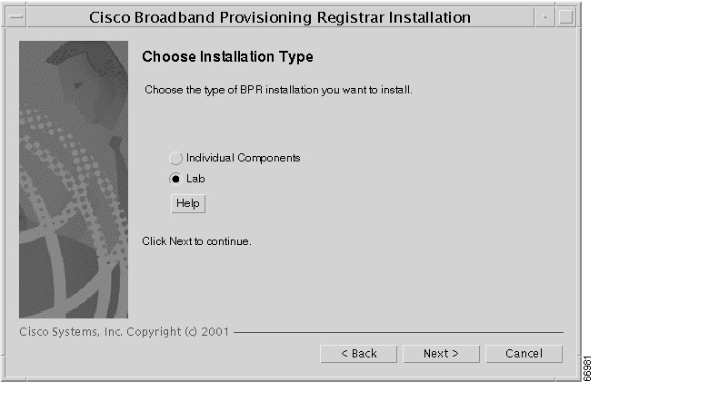
Step 2
Figure 4-1 Choose Installation Type Screen
Step 3
Caution
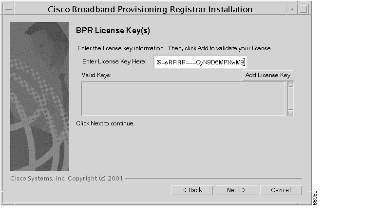
Provided that a TFTP server is not detected, the BPR License Key(s) screen appears ( Figure 4-2).
Figure 4-2 BPR License Key(s) Screen
Step 4
Note
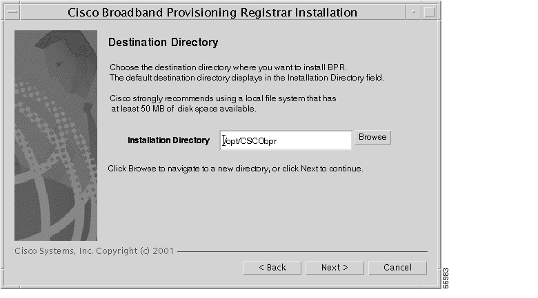
Step 5
Figure 4-3 Destination Directory Screen
Step 6
Step 7
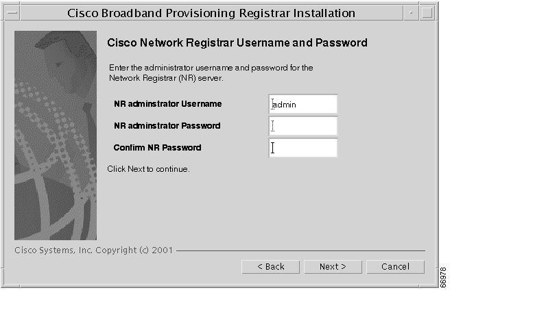
Figure 4-4 Network Registrar Username and Password Screen
Step 8
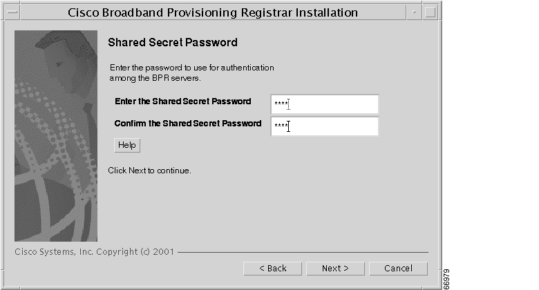
Step 9
Figure 4-5 Shared Secret Password Screen
Step 10
Step 11
a.
b.
c.
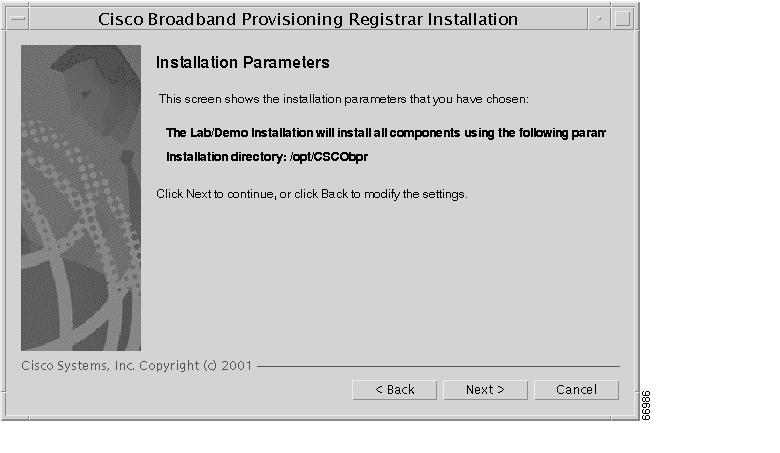
Figure 4-6 Lab Installation Parameters Screen
Step 12
Installing in a Lab Environment Using the CLI
The lab installation prompts for the following information:
•
•
•
To install BPR in a lab environment, complete the steps described in "Installing from the Command Line" section on page 2-7. Then, do the following:
Step 1
The program then prompts you to enter another license key.
Step 2
Validating LAB settings...The program then prompts you to enter the destination directory.
Step 3
Destination DirectoryDirectory path for BPR_HOMELocation BPR_HOMEInstallation Directory [/opt/CSCObpr]The program then asks you to confirm the directory.
Step 4
Step 5
a.
b.
For example:
Cisco Network Registrar Username and PasswordEnter the administrator username and password for the NR server.Enter the username and password for the NR server to be used in the labinstallation. You must confirm the NR password.Network Registrar adminstrator Username [admin] adminNetwork Registrar adminstrator Password [] changemeConfirm Network Registrar Password [] changemeThe program then redisplays the administrator username, password, and password confirmation. It then prompts you to confirm this information.
Step 6
Step 7
Shared Secret PasswordEnter the password to be used for authenticationamong the BPR servers.If you are performing a lab installation, then the password will be used forall the servers. If this is a component installation, then the password youenter must be the same as the components previously installed.Enter the Shared Secret Password [secret] secretThe program prompts you to confirm the password.
Step 8
Installation ParametersThis screen shows the installation parameters that you have chosen:========== Confirmation ==========The Lab/Demo Installation will install all components using the followingparameters:Installation directory:/opt/CSCObprIs this correct (y/n/q/?) [yes]Step 9
Configuring Network Registrar and a CMTS
For BPR to function in a lab environment you need to set up Network Registrar client-classes, policies, scopes, and selection tags. You also need to perform some configuration of CMTS devices.
To configure Network Registrar and CMTS devices, follow these steps:
Step 1
/opt/nwreg2/usrbin/nrcmd  -N <USER_NAME> -P <PASSWORD> -b  <
/opt/CSCObpr/cnr_ep/samples/bpr_cnr_hsd_sample_config.nrcmd > cnr_setup.out.
Note
Step 2
interface Cable3/0ip address 172.27.192.17 255.255.255.240 secondaryip address 172.27.192.33 255.255.255.240 secondaryip address 172.27.192.49 255.255.255.240 secondaryip address 172.27.192.1 255.255.255.240no ip directed-broadcastno keepalivecable downstream annex Bcable downstream modulation 64qamcable downstream interleave-depth 32cable downstream frequency 477000000cable upstream 0 frequency 26000000cable upstream 0 power-level 0no cable upstream 0 shutdowncable dhcp-giaddr primarycable helper-address <IP Address Of Your Network Registrar Server>Step 3
ip dhcp relay information optionThe default device detection logic in BPR uses DHCP option 82 information (relay-agent information) to detect devices.
Step 4
no ip dhcp relay information check
![]()
![]()
![]()
![]()
![]()
![]()
![]()
![]()
Posted: Tue Nov 30 14:32:09 PST 2004
All contents are Copyright © 1992--2004 Cisco Systems, Inc. All rights reserved.
Important Notices and Privacy Statement.