|
|

Table Of Contents
Threshold Performance Monitoring
Intermediate-Path Performance Monitoring
Optical Card Performance Monitoring
OC-48/STM16 and OC-192/STM64 Card Performance Monitoring Parameters
Performance Monitoring
Use performance monitoring (PM) parameters to gather, store, threshold, and report performance data for early detection of problems. This chapter defines PM parameters and concepts for CiscoONS15600SDH optical cards.
You can find additional PM information Telcordia GR-1230-CORE, GR-820-CORE, and GR-253 CORE, in ITU-T G.826, G.827, G.828, G.829, M2101, and M2102, and in the ANSI document titled Digital Hierarchy - Layer 1 In-Service Digital Transmission Performance Monitoring.
Chapter topics include:
•
Threshold Performance Monitoring
•
•
9.1 Threshold Performance Monitoring
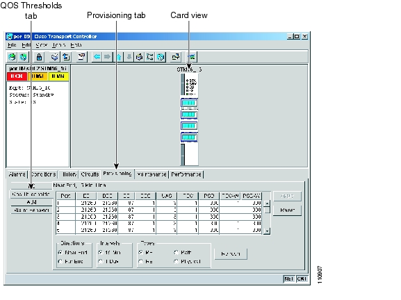
Thresholds are used to set error levels for each PM. You can program PM threshold ranges from the Provisioning > QoS Thresholds tabs on the Cisco Transport Controller (CTC) card view. To provision card thresholds, such as Regenerator Section, Multiplex Section, and High Order Path thresholds, refer to the Cisco ONS 15600 SDH Procedure Guide.
During the accumulation cycle, if the current value of a performance monitoring parameter reaches or exceeds its corresponding threshold value, a threshold crossing alert (TCA) is generated by the node and sent to CTC. TCAs provide early detection of performance degradation. When a threshold is crossed, the node continues to count the errors during a given accumulation period. If 0 is entered as the threshold value, the performance monitoring parameter is disabled. Figure9-1 shows the Provisioning > QoSThresholds tabs for an OC-48/STM-16 card.
Figure 9-1 QoS Thresholds Tab for Setting Threshold Values
Change the threshold if the default value does not satisfy your error monitoring needs. For example, customers with a critical VC4 installed for 911 calls must guarantee the best quality of service on the line; therefore, they lower all thresholds so that the slightest error raises a TCA.
9.2 Intermediate-Path Performance Monitoring
Intermediate-path performance monitoring (IPPM) allows a nonterminating node to transparently monitor a constituent channel of an incoming transmission signal. ONS15600SDH networks only use line terminating equipment (LTE), not path terminating equipment (PTE). Table9-1 shows ONS15600SDH cards that are considered LTE.
Table 9-1 Line Terminating Traffic Cards
OC48/STM16SR/SH 16Port1310
OC48/STM16LR/LH 16Port1550
OC192/STM64SR/SH 4Port1310
OC192/STM64LR/LH 4Port1550
Figure9-2 shows the Provisioning > AU4 tabs for an STM-16 card.
Figure 9-2 AU4 Tab for Enabling IPPM
Software Release 1.0 and later allows LTE cards to monitor near-end path PM data on individual VC4 payloads by enabling IPPM. After enabling IPPM on provisioned VC4 ports, service providers can monitor large amounts of VC4 traffic through intermediate nodes, thus making troubleshooting and maintenance activities more efficient.
IPPM occurs only on VC4 paths that have IPPM enabled, and TCAs are raised only for PM parameters on the selected IPPM paths. The monitored IPPMs are VC4 HP-EB, VC4 HP-ES, VC4 HP-SES, VC4HP-UAS, and VC4 HP-BBE. The following ratio parameters are provided: VC4HP-BBER, VC4HP-ESR, and VC4 HP-SESR. To enable IPPM, refer to the Cisco ONS 15600 Procedure Guide.
The ONS15600SDH performs IPPM by examining the overhead in the monitored path and reading all of the near-end path performance monitoring parameters in the incoming transmission direction. The IPPM process allows the path overhead to pass bidirectionally through the node completely unaltered.
For detailed information about specific performance monitoring parameters, see the "Optical Card Performance Monitoring" section .
9.3 Pointer Justification Count
Pointers are used to compensate for frequency and phase variations. Pointer justification counts indicate timing differences on SDH networks. When a network is not synchronized, frequency and phase variations occur on the transported signal. Excessive frequency and phase variations can cause terminating equipment to slip. These variations also cause slips at the SDH and plesiochronous digital hierarchy (PDH) boundaries.
Slips cause different effects in service. Voice service has intermittent audible clicks. Compressed voice technology has short transmission errors or dropped calls. Fax machines lose scanned lines or experience dropped calls. Digital video transmission has distorted pictures or frozen frames. Encryption service loses the encryption key, which causes data to be transmitted again.
Pointers align the phase variations in VC4 and TU payloads. The VC4 payload pointer is located in the H1 and H2 bytes of the line overhead. Clocking differences are measured by the offset in bytes from the pointer to the first byte of the VC4 Virtual Container (VC) called the J1 byte. A small number of pointer justification counts per day is not cause for concern. If the pointer justification count continues to rise or becomes large, action must be taken to correct the problem.
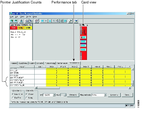
Figure9-3 shows pointer justification count parameters on the performance monitoring window. You can enable positive pointer justification count (PPJC) and negative pointer justification count (NPJC) performance monitoring parameters for LTE cards.
Figure 9-3 Viewing Pointer Justification Count Parameters
PPJC is a count of path-detected (PPJC-Pdet) or path-generated (PPJC-Pgen) positive pointer justifications depending on the specific PM name. NPJC is a count of path-detected (NPJC-Pdet) or path-generated (NPJC-Pgen) negative pointer justifications depending on the specific PM name.
A consistent pointer justification count indicates clock synchronization problems between nodes. A difference between the counts means the node transmitting the original pointer justification has timing variations with the node detecting and transmitting this count. Positive pointer adjustments occur when the frame rate of the VC is too slow in relation to the rate of the VC4.
For pointer justification count definitions, see the "Optical Card Performance Monitoring" section . In CTC, the PM count fields for PPJC and NPJC appear white and blank unless IPPM is enabled.
Note
9.4 Optical Card Performance Monitoring
The following sections define performance monitoring parameters for the OC-48/STM16 and OC-192/STM64 optical cards.
9.4.1 OC-48/STM16 and OC-192/STM64 Card Performance Monitoring Parameters
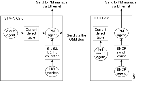
Figure9-4 shows where overhead bytes detected on the application-specific integrated circuits (ASICs) produce performance monitoring parameters for the OC-48/STM16 and OC-192/STM64 optical cards.
Figure 9-4 PM Read Points on the OC-48/STM16 and OC-192/STM64 Cards
Table9-2 defines the near-end regenerator section layer PMs.
Table 9-2 Near-End Regenerator Section Performance Monitoring Parameters for the OC-48/STM16
and OC-192/STM64 CardsRegenerator Section Errored Block (RS-EB) indicates that one or more bits are in error within the block.
10000 (15 Min)
100000 (1 Day)
Regenerator Section Background Block Error (RS-BBE) is an errored block not occurring as part of RS-SES.
10000 (15 Min)
100000 (1 Day)
Regenerator Section Errored Seconds (RS-ES) indicates the count of number of seconds when at least one RS-layer EDC (Error Detection Code) error was detected or a Loss Of Signal (LOS) defect was present.
500 (15 Min)
5000 (1 Day)
Regenerator Section Severely Errored Seconds (RS-SES) is a count of seconds where K or more EDC RS-layer errors were detected or an LOS defect was present.
500 (15 Min)
5000 (1 Day)
1 The default TCA value might vary depending your system configuration and specific requirements.
Table9-3 defines the near-end and far-end multiplex section layer PMs.
Table 9-3 Near-End and Far-End Multiplex Section Layer Performance Monitoring Parameters for the OC-48/STM16 and OC-192/STM64 Cards
Multiplex Section Errored Block (MS-EB).
Near-End MS-EB indicates that one or more bits are in error (EDC error) within a block.
Far-End MS-EB indicates that one or more MS-REI (Multiplex Section-Remote Error Indication) occurs in a block.
21260 (15 Min) STM16
85040 (15 Min) STM64
212600 (1 Day) STM16
850400 (1 Day) STM64
Multiplex Section Background Block Error (MS-BBE) is an errored block not occurring as part of an MS-SES.
21260 (15 Min) STM16
85040 (15 Min) STM64
212600 (1 Day) STM16
850400 (1 Day) STM64
Multiplex Section Errored Seconds (MS-ES).
A Near-End MS-ES indicates the count of the number of seconds when at lease one MS-layer EDC error was detected or one defect MS-AIS (Multiplex Section-Alarm Indication Signal) occurred.
A Far-End MS-ES indicates the count of the number of seconds when at least on MS-REI (Multiplex Section-Remote Error Indication) was detected or one MS-RDI (Multiplex Section Remote Defect Indication) occurred.
87 (15 Min
864 (1 Day)
Multiplex Section Severely Errored Seconds (MS-SES).
A Near-End MS-SES is a count of the number of seconds when K (see G.826-G.829 ITU-T) or more EDC MS-layer errors were detected or MS-AIS occurred. (See ITU-T G.829 for further details.)
A Far-End MS-SES is a count of the number of seconds when at least K EBs (Errored Blocks0 derived from MS-REI or MS-RDI occurred. (See ITU-T G.829 for further details.)
1 (15 Min)
4 (1 Day)
Near-End/Far-End Multiplex Section Unavailable Seconds (MS-UAS) is a count of the seconds when the section is unavailable. A section becomes unavailable when ten consecutive seconds occur that qualify as MS-SESs, and it continues to be unavailable until ten consecutive seconds occur that do not qualify as MS-SESs.
3 (15 Min)
10 (1 Day)
1 The default TCA value might vary depending your system configuration and specific requirements.
Table9-4 defines the near-end SDH Path H-Byte PMs.
Table 9-4 Near-End SDH Path H-Byte Performance Monitoring Parameters for the OC-48/STM16
and OC-192/STM64 CardsPositive Pointer Justification Count, VC4 Path Detected (PPJC-Pdet) is a count of the positive pointer justifications detected on a particular path on an incoming SDH signal.
60 (15 Min)
5760 (1 Day)
VC4 Path Detected (NPJC-Pdet) is a count of the negative pointer justifications detected on a particular path on an incoming SDH signal.
60 (15 Min)
5760 (1 Day)
Positive Pointer Justification Count, VC4 Path Generated (PPJC-Pgen) is a count of the positive pointer justifications generated for a particular path to reconcile the frequency of the VC with the local clock.
60 (15 Min)
5760 (1 Day)
Negative Pointer Justification Count, VC4 Path Generated (PPJC-Pgen) is a count of the negative pointer justifications generated for a particular path to reconcile the frequency of the VC with the local clock.
60 (15 Min)
5760 (1 Day)
1 The default TCA value might vary depending your system configuration and specific requirements.
For information about troubleshooting SNCP switch counts, refer to the Cisco ONS 15600 SDH Troubleshooting Guide. For information about creating circuits with protection switching, see Chapter6, "Circuits and Tunnels."
Table9-5 defines the near-end protection switching PMs.
Table 9-5 Near-End Protection Switching Performance Monitoring Parameters for the OC-48/STM16
and OC-192/STM64 CardsIn a 1 + 1 protection scheme for a working card, Multiplex Section Protection Switch Count (MS-PSC) is a count of the number of times service switches from a working card to a protection card plus the number of times service reverts to the working card.
For a protection card, MS-PSC is a count of the number of times service switches to a working card from a protection card plus the number of times service reverts to the protection card. The MS-PSC PM is only applicable if revertive line-level protection switching is used.
1 (15 Min)
5 (1 Day)
For an active protection line, Multiplex Section Protection Switch Duration (MS-PSD) is a count of the number of seconds that the protect line is carrying working traffic following the failure of the working line. MS-PSD counts on the active protect line.
300 (15 Min)
600 (1 Day)
For a working line in a two-fiber MS-SPRing, Multiplex Section Protection Switching Count-Working (MS-PSC-W) is a count of the number of times traffic switches away from the working capacity in the failed line and back to the working capacity after the failure is cleared. MS-PSC-W increments on the failed working line and MS-PSC increments on the active protect line.
1 (15 Min)
5 (1 Day)
For a working line in a two-fiber MS-SPRing, Multiplex Section Protection Switching Duration-Working (MS-PSD-W) is a count of the number of seconds that service was carried on the protection line. MS-PSD-W increments on the failed working line and MS-PSD increments on the active protect line.
300 (15 Min)
600 (1 Day)
1 The default TCA value might vary depending on your system configuration and specific requirements.
SDH path performance monitoring parameters increment only if IPPM is enabled. For additional information, see the "Intermediate-Path Performance Monitoring" section .
Table9-6 defines the near-end and far-end SDH high order path PMs.
Table 9-6 Near-End and Far-End SDH Path Performance Monitoring Parameters for the OC-48/STM16 and OC-192/STM64 Cards
High Order Path Errored Block (HP-EB).
Near-End HP-EB indicates that one or more bits are in error within a block.
Far-End HP-EB indicates that one or more HP-REI occurs in aa block.
25 (15 Min) VC4
75 (15 Min) VC4-4c and greater
250 (1 Day) VC4
750 (1 Day) VC4-4c and greater
High Order Path Background Block Error (HP-BBE).
A Near-End/Far-End HP-BBE indicates an errored block not occurring as part of an HP-SES.
25 (15 Min)
250 (1 Day)
High Order Path Errored Seconds (HP-ES)
A Near-End HP-ES indicates the count of the number of seconds when at least one path-layer EDC error was detected or one among AU-LOP (Administration Unit-Loss of Power), AU-AIS (Administration unit-Alarm Indication Signal, HP-TIM (High Order Path-Trace Identifier Mismatch), or HP-UNEQ (High Order Path-Unequipped) defects occurred. (See ITU-T G.826 for further details.)
A Far-End HP-ES indicates the count of the number of seconds when at least one HP-REI was detected or an HP-RDI (High Order Path-Remote Defect Indication) defect occurred.
20 (15 Min) VC4
60 (15 Min) VC4-4c and greater
200 (1 Day) VC4
600 (1 Day) VC4-4c and greater
High Order Path Severely Errored Seconds (HP-SES).
A Near-End HP-SES is a count of the seconds when K (2400) or more EDC HP-layer errors were detected or one among AU-LOP, AU-AIS, HP-TIM or HP-UNEQ defect occurred. (See ITU-T G.826 for further details.)
A Far-End HP-SES is a count of the seconds when at least K (2400) EBs (Errored Blocks) derived from HP-REI errors were detected or an HP-RDI defect occurred. (See ITU-T G.829 for further details.)
HP-SES is a subset of HP-ES.
3 (15 Min)
7 (1 Day)
Near-End/Far-End High Order Path Unavailable Seconds (VC4 HP-UAS) is a count of the seconds when the high order (HO) path (VC4) was unavailable. An HO path becomes unavailable when ten consecutive seconds occur that qualify as HP-SESs, and it continues to be unavailable until ten consecutive seconds occur that do not qualify as HP-SESs.
10 (15 Min)
10 (1 Day)
Near-End/Far-End High Order Path Errored Second Ratio (HP-ESR) is the ratio of errored seconds to total seconds in available time during a fixed measurement interval.
—
Near-End/Far-End High Order Path Severely Errored Second Ratio (HP-SESR) is the ratio of HP-SES to total seconds in available time during a fixed measurement interval.
—
Near-End/Far-End High Order Path Background Block Error Ratio (HP-BBER) is the ratio of Background Block Errors (HP-BBE) to total blocks in available time during a fixed measurement interval. The count of total blocks excludes all blocks during HP-SESs.
—
1 The default TCA value might vary depending your system configuration and specific requirements.
9.4.2 Physical Layer Parameters
The ONS15600SDH retrieves the optical power received (OPR), optical power transmitted (OPT), and laser bias current (LBC) from the line card and stores these values with the PM counts for the 15-minute and 1-day periods. You can retrieve current OPR, OPT, and LBC values for each port by displaying the card view in CTC and clicking the Maintenance > Transceiver tabs.
The physical layer performance parameters consist of normalized and nonnormalized values of LBC, OPT, and OPR. Table9-7 defines the nonnormalized values.
Table 9-7 Nonnormalized Transceiver Physical Optics for the OC-48/STM16 and OC-192/STM64 Cards
The actual operating value of laser bias current (mA) for the specified card port.
The actual operating value of optical power transmitted (dBm) for the specified card port.
Nonnormalized OPT (dBm)2
The actual operating value of optical power received (dBm) for the specified card port.
1 This value should be somewhat consistent from port to port and cannot be configured.
2 This value will vary from port to port because of received optical signal power differences. This value can be configured by calibrating the nominal value to the initial receive power level when the port is put in service.
The normalized physical layer performance parameters are represented as a percentage of the nominal operating value, with 100 representing the nominal value. Table9-8 defines the normalized physical layer performance parameters.
Table 9-8 Physical Optics Performance Monitoring Parameters for the OC-48/STM16 and OC-192/STM64 Cards
Laser bias current (LBC) is represented by the percentage of the normal (100%) laser bias current of the laser on the card port. The high laser bias current (LBC-HIGH) threshold is the percentage of the normal laser bias current when a high current TCA occurs. The low laser bias current (LBC-LOW) threshold is the percentage of the normal laser bias current when a low current TCA occurs.
200 (LBC-HIGH)
20 (LBC-LOW)
Optical power transmitted (OPT) is represented by the percentage of the normal (100%) optical transmit power of the laser on the card port. The high optical power transmitted (OPT-HIGH) threshold is the percentage of the normal transmit optical power when a high transmit power TCA occurs. The low optical power transmitted (OPT-LOW) threshold is the percentage of the normal transmit optical power when a low transmit power TCA occurs.
120 (OPT-HIGH)
80 (OPT-LOW)
Optical power received (OPR) is represented by the percentage of the normal optical receive power of the card port. The high optical power received (OPR-HIGH) threshold is the percentage of the calibrated receive optical power when a high receive power TCA occurs. The low optical power received (OPR-LOW) threshold is the percentage of the calibrated receive optical power when a low receive power TCA occurs.
200 (OPR-HIGH)
50 (OPR-LOW)
1 As stated in Telcordia GR-253-CORE, the LBC (TCA) PM value is not appropriate for use with some optical transmitter technologies. Such is the case for Cisco's uncooled SR optical transmitters. The default LBC TCA provides safe operating parameter for both of Cisco's cooled and uncooled transmitters.
To set the threshold values for LBC, OPT, and OPR, and to reset the OPR nominal value for future calculation, refer to the Cisco ONS 15600 SDH Procedure Guide.
![]()
![]()
![]()
![]()
![]()
![]()
![]()
![]()
Posted: Fri Feb 27 18:35:12 PST 2004
All contents are Copyright © 1992--2004 Cisco Systems, Inc. All rights reserved.
Important Notices and Privacy Statement.