|
|

Table Of Contents
Viewing Circuit Information on the Edit Circuit Window
Multiple Drops for Unidirectional Circuits
Bandwidth Allocation and Routing
Constraint-Based Circuit Routing
Circuit Bridge and Roll Restrictions
Circuits and Tunnels
This chapter explains CiscoONS15600SDH VC4 high-order circuits and data communications channel (DCC) tunnels. To provision circuits and tunnels, refer to the CiscoONS15600SDH Procedure Guide.
Chapter topics include:
•
Multiple Drops for Unidirectional Circuits
•
Note
6.1 Circuit Properties
The ONS15600SDH supports unidirectional and bidirectional circuits. Subnetwork connection protection (SNCP) or multiplex section-shared protection ring (MS-SPRing) circuits can be revertive or nonrevertive. Circuits will route automatically or you can manually route them. The autorange feature eliminates the need to build circuits of the same type individually; Cisco Transport Controller (CTC) can create up to five sequential circuits. You must specify the number of circuits that you need and build the first circuit.
You can provision circuits at either of the following points:
•
•
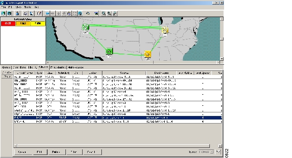
The ONS15600SDH Circuits window ( Figure6-1), which is available from network, node, and card view, is where you can view information about circuits, including:
•
•
•
•
•
•
•
•
•
•
•
Note
Figure 6-1 ONS 15600 SDH Circuit Window in Network View
6.1.1 Circuit Status
The circuit statuses that appear in the Circuit window Status column are generated by CTC based on an assessment of conditions along the circuit path. Table6-1 lists the statuses that can appear in the Status column.
Table 6-1 ONS 15600 SDH Circuit Status
CREATING
CTC is creating a circuit.
ACTIVE
CTC created a circuit. All components are in place and a complete path exists from circuit source to destination.
DELETING
CTC is deleting a circuit.
INCOMPLETE
A CTC-created circuit is missing a connection or circuit span (network link), a complete path from source to destination(s) does not exist, or a MAC address change occurred on one of the circuit nodes and the circuit is in need of repair. (In the ONS 15454 SDH, the MAC address resides on the alarm interface panel [AIP]; in the ONS15600SDH, the MAC address resides on the backplane EEPROM.)
In CTC, circuits are represented using cross-connects and network spans. If a network span is missing from a circuit, the circuit status is INCOMPLETE. However, an INCOMPLETE status does not necessarily mean a circuit traffic failure has occurred because traffic might be on a protect path.
Network spans are in one of two states: up or down. On CTC circuit and network maps, up spans appear as green lines ( Figure6-1) and down spans appear as gray lines. If a failure occurs on a network span during a CTC session, the span remains on the network map but its color changes to gray to indicate the span is down. If you restart your CTC session while the failure is active, the new CTC session cannot discover the span and its span line will not appear on the network map.
Subsequently, circuits routed on a network span that goes down will appear as ACTIVE during the current CTC session, but they will appear as INCOMPLETE to users who log in after the span failure.
UPGRADABLE
A TL1-created circuit or a TL1-like CTC-created circuit is complete and has upgradable cross-connects. A complete path from source to destination(s) exists. The circuit can be upgraded.
INCOMPLETE_UPGRADABLE
A TL1-created circuit or a TL1-like CTC-created circuit with upgradable cross-connects is missing a cross-connect or circuit span (network link), and a complete path from source to destination(s) does not exist. The circuit cannot be upgraded until missing components are in place.
NOT_UPGRADABLE
A TL1-created circuit or a TL1-like CTC-created circuit is complete but has at least one nonupgradable cross-connect. SNCP_HEAD, SNCP_EN, SNCP_DC, and SNCP_DROP connections are not upgradable so all unidirectional SNCP circuits created with TL1 are not upgradable.
INCOMPLETE_NOT_UPGRADABLE
A TL1-created circuit or a TL1-like CTC-created circuit with one or more nonupgradable cross-connects is missing a cross-connect or circuit span (network link); a complete path from source to destination(s) does not exist.
ROLL_PENDING
Roll is awaiting completion or cancellation. When a roll is in the ROLL PENDING state, you can complete a manual roll and cancel an automatic or manual roll.
6.1.2 Circuit Protection Types
The Protection column on the Circuit window shows the card (MS) and SDH topology (AU4) protection used for the entire circuit path. Table6-2 lists the protection type indicators that you will see in this column.
6.1.3 Viewing Circuit Information on the Edit Circuit Window
When Show Detailed Map is checked on the Edit Circuit window, you can view information about ONS15600SDH circuits. Routing information includes:
•
•
•
•
•
For MS-SPRings, the detailed map shows the number of MS-SPRing fibers and the MS-SPRing ring ID. For SNCPs, the map shows the active and standby paths from circuit source to destination, and it also shows the working and protect paths.
Alarms and states can also be viewed on the circuit map, including:
•
•
•
•
•
•
•
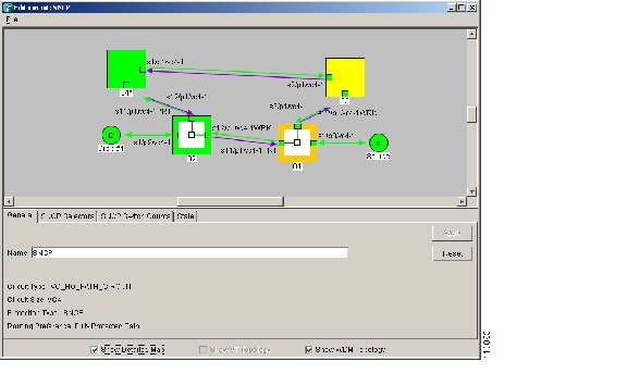
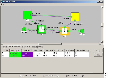
Figure6-2 shows a bidirectional VC4 circuit routed on an SNCP.
Figure 6-2 SNCP Circuit on the Edit Circuits Window
By default, the working path is indicated by a green, bidirectional arrow, and the protect path is indicated by a purple, bidirectional arrow. Source and destination ports are shown as circles with an S and D, respectively. Port status is indicated by colors, shown in Table6-3.
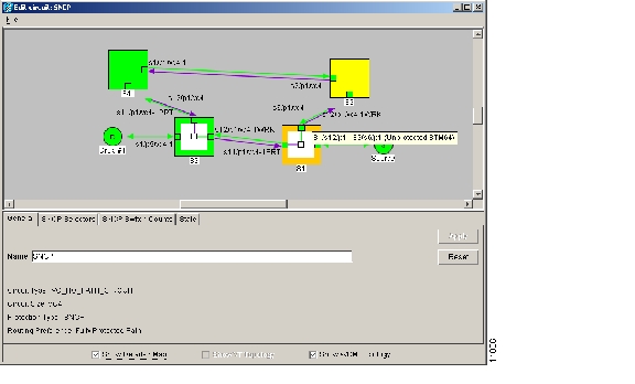
Figure6-3 shows a popup for an SNCP span. The detailed circuit map also provides popup span information for MS-SPRings.
Figure 6-3 Detailed Circuit Map Showing Span Information
In addition to providing circuit information, the detailed circuit map allows you to add a drop and initiate a path trace:
•
•
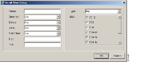
6.1.4 Circuit Filter
The ONS15600SDH will support up to 2048 VC4 circuits. The Circuit Filter feature allows you to reduce the number of circuits that appear on the Circuits window ( Figure6-4). You can specify certain filter criteria, such as name, direction, and state; only the circuits that match the criteria will appear on the Circuits window.
Figure 6-4 Filtering Circuits
6.2 DCC Tunnels
SDH provides four DCCs for network element Operation, Administration, Maintenance, and Provisioning (OAM&P): one on the SDH regenerator section (RS) layer (DCC1) and three on the SDH multiplex section (MS) layer (DCC2, DCC3, DCC4). The ONS15600SDH uses the RS DCC for ONS15600SDH management and provisioning.
You can use the three MS DCCs and the RS DCC (when not used for ONS15600SDH DCC terminations) to tunnel third-party SDH equipment across ONS15600SDH networks. A DCC tunnel endpoint is defined by slot, port, and DCC, where DCC can be either the RS DCC or one of the MSDCCs. You can link MS DCCs to MS DCCs and link RS DCCs to RS DCCs. You can also link a RSDCC to a MS DCC and a MS DCC to a RS DCC. To create a DCC tunnel, connect the tunnel endpoints from one ONS15600SDH optical port to another.
Table6-4 lists the DCC tunnels that you can create.
Table 6-4 DCC Tunnels
DCC1
RS
D1 to D3
DCC2
MS
D4 to D6
DCC3
MS
D7 to D9
DCC4
MS
D10 to D12
When you create DCC tunnels, keep the following guidelines in mind:
•
•
•
•
6.3 Multiple Drops for Unidirectional Circuits
Unidirectional circuits can have multiple drops for use in broadcast circuit schemes. In broadcast scenarios, one source transmits traffic to multiple destinations, but traffic is not returned to the source. The ONS15600SDH supports either of the following:
•
•
When you create a unidirectional circuit, the card that does not have its backplane receive (Rx) input terminated with a valid input signal generates a loss of service (LOS) alarm. To mask the alarm, create an alarm profile suppressing the LOS alarm and apply the profile to the port that does not have its Rx input terminated.
6.4 SNCP Circuits
Use the Edit Circuits window to change SNCP selectors and switch protection paths ( Figure6-5). In the SNCP Selectors tab, you can:
•
•
•
Figure 6-5 Editing SNCP Selectors
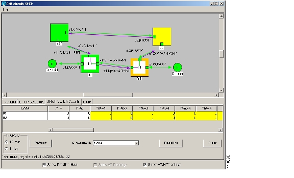
On the SNCP Switch Counts tab, you can view switch counts for the selectors ( Figure6-6).
Figure 6-6 Viewing SNCP Switch Counts
6.5 Path Trace
The SDH J1 Path Trace is a repeated, fixed-length string that includes 64 or 16 consecutive J1 bytes. You can use the string to monitor interruptions or changes to circuit traffic. Table6-5 lists the ONS15600SDH cards that support path trace. Cards not listed in the table do not support the J1 byte.
The J1 path trace transmits a repeated, fixed-length string. If the string received at a circuit drop port does not match the string the port expects to receive, an alarm is raised.
The ONS15600SDH supports manual J1 path trace monitoring to detect and report the contents of the 64-byte VC4 path trace message (nonterminated) for the designated VC4 path. You can also modify the expected path trace message. The ONS15600SDH does not support path trace auto mode or allow you to modify a transmitted path trace message.
The ONS15600SDH can also monitor a 16-byte ITU pattern.
6.6 Automatic Circuit Routing
If you select automatic routing during circuit creation, CTC routes the circuit by dividing the entire circuit route into segments based on protection schemes. For unprotected segments of protected circuits, CTC finds an alternate route to protect the segment in a virtual SNCP fashion. Each path segment is a separate protection scheme, and each protection scheme is protected in a specific fashion (virtual SNCP or 1+1).
The following list provides principles and characteristics of automatic circuit routing:
•
•
•
•
6.6.1 Bandwidth Allocation and Routing
Within a given network, CTC will route circuits on the shortest possible path between source and destination based on the circuit attributes, such as protection and type. CTC will consider using a link for the circuit only if the link meets the following requirements:
•
•
If CTC cannot find a link that meets these requirements, an error appears.
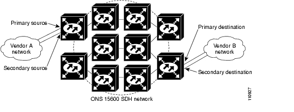
6.6.2 Secondary Sources and Drops
CTC supports secondary sources and drops. Secondary sources and drops typically interconnect two networks containing equipment from different vendors, as shown in Figure6-7. Traffic is protected while it traverses a network of ONS15600SDH nodes.
Figure 6-7 Secondary Sources and Drops
Several rules apply to secondary sources and drops:
•
•
•
•
For bidirectional circuits, CTC creates an SNCP connection at the source node that allows traffic to be selected from one of the two sources on the ONS15600SDH network. If you check the FullyPathProtected option during circuit creation, traffic is protected within the ONS15600SDH network. At the destination, another SNCP connection is created to bridge traffic from the ONS15600SDH network to the two destinations. A similar but opposite path exists for the reverse traffic flowing from the destinations to the sources.
For unidirectional circuits, an SNCP drop-and-continue connection is created at the source node.
6.7 Manual Circuit Routing
Routing circuits manually allows you to:
•
•
CTC imposes the following rules on manual routes:
•
•
•
If Fully Protected Path is chosen, CTC verifies that the route selection is protected at all segments. A route can have multiple protection schemes with each scheme protected by a different mechanism.
Table6-6 summarizes the available bidirectional connections. Any other combination is invalid and will generate an error.
Table6-7 summarizes the available unidirectional connections. Any other combination is invalid and will generate an error.
6.8 Constraint-Based Circuit Routing
When you create circuits, you can choose Fully Protected Path to protect the circuit from source to destination. The protection mechanism used depends on the path that CTC calculates for the circuit. If the network is comprised entirely of 1+1 links, or the path between source and destination can be entirely protected using 1+1 links, no Extended SNCP Mesh Networks protection is used.
If Extended SNCP Mesh Networks protection is needed to protect the path, set the level of node diversity for the Extended SNCP Mesh Networks portions of the complete path on the Circuit Creation dialog box:
•
•
•
When you choose automatic circuit routing during circuit creation, you have the option to require and/or exclude nodes and links in the calculated route. You can use this option to achieve the following results:
•
•
CTC considers required nodes and links to be an ordered set of elements. CTC treats the source nodes of every required link as required nodes. When CTC calculates the path, it makes sure the computed path traverses the required set of nodes and links and does not traverse excluded nodes and links.
The required-nodes-and-links constraint is used only during the primary path computation and only for Extended SNCP Mesh Networks segments. The alternate path is computed normally; CTC uses excluded nodes/links when finding all primary and alternate paths on Extended SNCP Mesh Networks.
6.9 Bridge and Roll
The Bridge and Roll wizard reroutes live traffic without interrupting service. The bridge process takes traffic from a designated "roll from" facility and establishes a cross connect to the designated "roll to" facility. After the bridged signal at the receiving end point is verified, the roll process creates a new cross-connect to receive the new signal. After the roll completes, the original cross-connects are released. You can use the bridge and roll feature for maintenance functions such as card or facility replacement, or for load balancing.
Note
6.9.1 Roll States
Table6-8 lists the roll states.
Table 6-8 Roll States
ROLL_PENDING
Roll is awaiting completion or cancellation.
ROLL_CANCELLED
Roll has been canceled.
Note
6.9.2 Roll Window
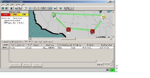
The Rolls window lists information about a rolled circuit before the roll process is complete. You can access the Rolls window by clicking the Circuits > Rolls tabs in either network or node view. Figure6-8 shows the Rolls window.
Figure 6-8 Rolls Window
The Rolls window options include:
•
•
•
•
–
–
•
•
•
•
•
•
6.9.3 Single and Dual Rolls
Circuits have an additional layer of roll types, single and dual. A single roll on a circuit is a roll on one of its cross-connections. Use a single roll to:
•
•
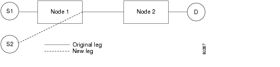
In Figure6-9, you can select any available VC4 on Node 1 for a new source.
Figure 6-9 Single Source Roll
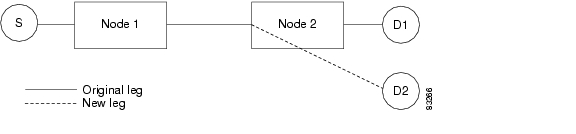
In Figure6-10, you can select any available VC4 on Node 2 for a new destination.
Figure 6-10 Single Destination Roll
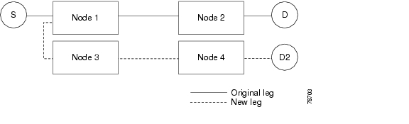
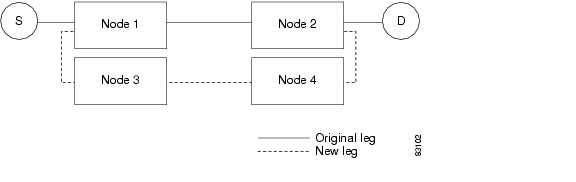
Figure6-11 shows one circuit rolling onto another circuit. The new circuit has cross-connections on Node 1, Node 3, and Node 4. CTC deletes the cross-connection on Node 2 after the roll.
Figure 6-11 Single Roll from One Circuit to Another Circuit
A dual roll involves two cross-connections. It allows you to reroute intermediate segments of a circuit, but keep the original source and destination. You can perform a dual roll on a single circuit or two circuits. When rolling two cross-connections using the CTC Bridge and Roll wizard, you can choose an existing circuit or create a new circuit. The created circuit is designated with the same name as the original circuit with the suffix _ROLL**.
Several constraints exist for dual rolls:
•
•
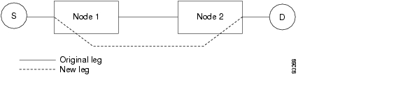
Figure6-12 illustrates a dual roll on the same circuit.
Figure 6-12 Dual Roll on the Same Circuit
Figure6-13 illustrates a dual roll involving two circuits.
Figure 6-13 Dual Roll on Two Circuits
6.9.4 Circuit Bridge and Roll Restrictions
Several restrictions apply when using the bridge and roll feature to reroute traffic using two circuits:
•
•
•
•
6.9.5 Protected Circuits
CTC allows you to roll the working or protect path regardless of which is active. You can upgrade an unprotected circuit to a fully protected circuit or downgrade a 1+1-protected circuit to an unprotected circuit.
When using bridge and roll on SNCP circuits, you can roll the source or destination or both path selectors in a dual roll. However, you cannot roll a single path selector.
You can also perform bridge and roll on MS-SPRing circuits.
![]()
![]()
![]()
![]()
![]()
![]()
![]()
![]()
Posted: Thu Feb 26 17:31:40 PST 2004
All contents are Copyright © 1992--2004 Cisco Systems, Inc. All rights reserved.
Important Notices and Privacy Statement.