|
|

Table Of Contents
ONS 15600 SDH IP Addressing Scenarios
Scenario 1: CTC and ONS 15600 SDH Nodes in the Same Subnet
Scenario 2: CTC and ONS 15600 SDH Nodes Connected to Router
Scenario 3: Using Proxy ARP to Enable an ONS 15600 SDH Gateway
Scenario 4: Default Gateway on CTC Computer
Scenario 5: Using Static Routes to Connect to LANs
Scenario 7: Provisioning the ONS 15600 SDH Proxy Server
IP Networking
This chapter provides seven scenarios showing CiscoONS15600SDH nodes in common IP network configurations. The chapter does not provide a comprehensive explanation of IP networking concepts and procedures.
For IP setup instructions, refer to the CiscoONS15600SDH Procedure Guide.
Chapter topics include:
•
ONS15600SDH IP Addressing Scenarios
Note
8.1 IP Networking Overview
ONS15600SDH nodes can be connected in many different ways within an IP environment:
•
•
•
•
•
8.2 ONS 15600 SDH IP Addressing Scenarios
ONS15600SDH IP addressing generally has seven common scenarios or configurations. Use the scenarios as building blocks for more complex network configurations. Table8-1 provides a general list of items to check when setting up ONS15600SDH nodes in IP networks.
8.2.1 Scenario 1: CTC and ONS 15600 SDH Nodes in the Same Subnet
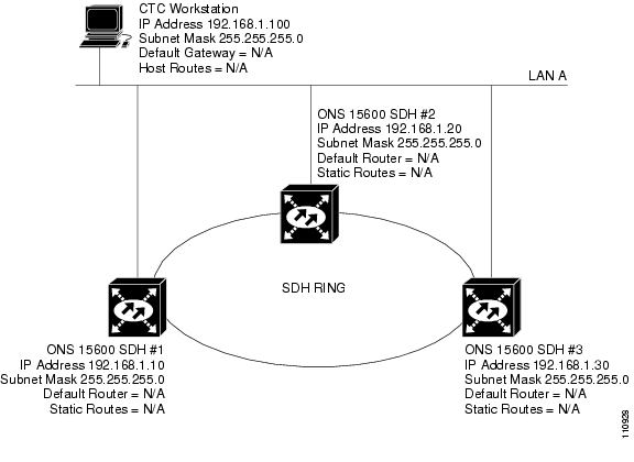
Scenario 1 shows a basic ONS15600SDH LAN configuration ( Figure8-1). The ONS15600SDH nodes and CTC computer reside on the same subnet. All ONS15600SDH nodes connect to LAN A, and all ONS15600SDH nodes have DCC connections.
Figure 8-1 Scenario 1: CTC and ONS 15600 SDH Nodes on Same Subnet
8.2.2 Scenario 2: CTC and ONS 15600 SDH Nodes Connected to Router
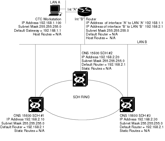
In Scenario 2, the CTC computer resides on a subnet (192.168.1.0) and attaches to LAN A ( Figure8-2). The ONS15600SDH nodes reside on a different subnet (192.168.2.0) and attach to LAN B. A router connects LAN A to LAN B. The IP address of router interface A is set to LAN A (192.168.1.1), and the IP address of router interface B is set to LAN B (192.168.2.1).
On the CTC computer, the default gateway is set to router interface A. If the LAN uses Dynamic Host Configuration Protocol (DHCP), the default gateway and IP address are assigned automatically. In the Figure8-2 example, a DHCP server is not available.
Figure 8-2 Scenario 2: CTC and ONS 15600 SDH Nodes Connected to Router
8.2.3 Scenario 3: Using Proxy ARP to Enable an ONS 15600 SDH Gateway
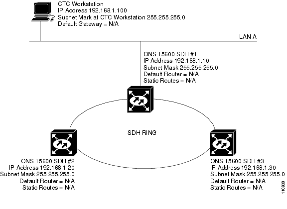
Scenario 3 is similar to Scenario 1, but only one ONS15600SDH (Node 1) connects to the LAN ( Figure8-3). Two ONS15600SDH nodes (Nodes 2 and 3) connect to Node 1 through the SDH DCC. Because all three ONS15600SDH nodes are on the same subnet, Proxy ARP enables Node 1 to serve as a gateway for Nodes 2 and 3.
Note
Figure 8-3 Scenario 3: Using Proxy ARP
ARP matches higher-level IP addresses to the physical addresses of the destination host. It uses a lookup table (called the ARP cache) to perform the translation. When the address is not found in the ARP cache, a broadcast is sent out on the network with a special format called the ARP request. If one of the machines on the network recognizes its own IP address in the request, it sends an ARP reply back to the requesting host. The reply contains the physical hardware address of the receiving host. The requesting host stores this address in its ARP cache so that all subsequent datagrams (packets) to this destination IP address can be translated to a physical address.
Proxy ARP enables one LAN-connected ONS15600SDH to respond to the ARP request for ONS15600SDH nodes that are not connected to the LAN. (ONS15600SDH Proxy ARP requires no user configuration.) For this response to occur, the DCC-connected ONS15600SDH nodes must reside on the same subnet. When a LAN device sends an ARP request to an ONS15600SDH that is not connected to the LAN, the gateway ONS15600SDH returns its MAC address to the LAN device. The LAN device then sends the datagram for the remote ONS15600SDH to the MAC address of the proxy ONS15600SDH. The proxy ONS15600SDH uses its routing table to forward the datagram to the non-LAN ONS15600SDH.
8.2.4 Scenario 4: Default Gateway on CTC Computer
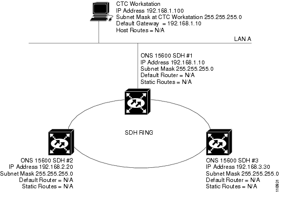
Scenario 4 is similar to Scenario 3, but Nodes 2 and 3 reside on different subnets, 192.168.2.0 and 192.168.3.0, respectively ( Figure8-4). Node 1 and the CTC computer are on subnet 192.168.1.0. For the CTC computer to communicate with Nodes 2 and 3, you would enter Node 1 as the default gateway on the CTC computer.
Figure 8-4 Scenario 4: Default Gateway on a CTC Computer
8.2.5 Scenario 5: Using Static Routes to Connect to LANs
Use static routes for the following two reasons:
•
•
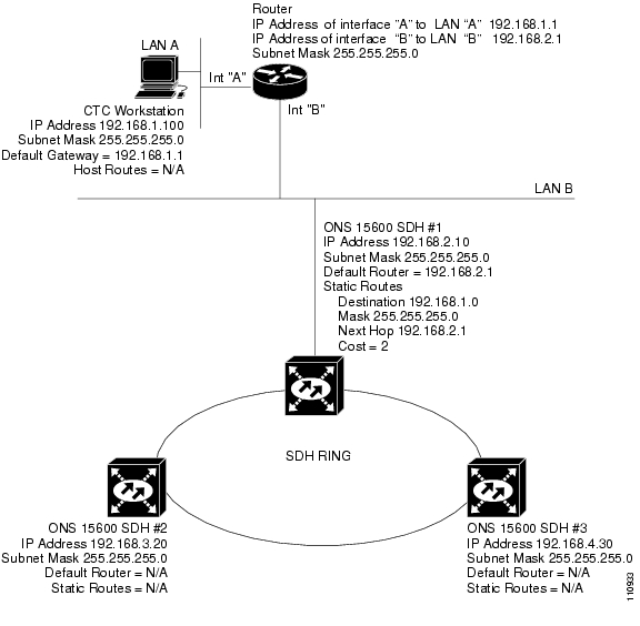
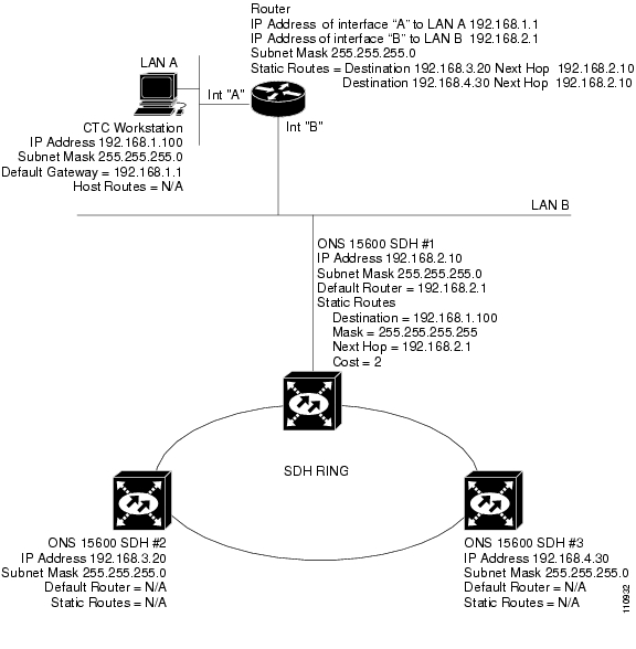
In Figure8-5, one CTC residing on subnet 192.168.1.0 connects to a router through interface A. (The router is not set up with OSPF.) ONS15600SDH nodes residing on subnet 192.168.2.0 are connected through Node 1 to the router through interface B. To connect to CTC computers on LAN A, you would create a static route on Node 1.
Figure 8-5 Scenario 5: Static Route with One CTC Computer Used as a Destination
The destination and subnet mask entries control access to the ONS15600SDH nodes:
•
•
•
The IP address of router interface B is entered as the next hop (the next router that a packet traverses to reach its destination), and the cost (number of hops from source to destination) is 2.
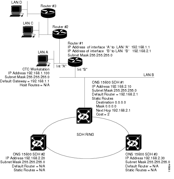
Figure 8-6 Scenario 5: Static Route with Multiple LAN Destinations
8.2.6 Scenario 6: Using OSPF
OSPF is a link state Internet routing protocol. Link state protocols use a hello protocol to monitor their links with adjacent routers and to test their links with their neighbors. Link state protocols advertise their directly connected networks and their active links. Each link state router captures the link state advertisements (LSAs) and puts them together to create a topology of the entire network or area. From this database, the router calculates a routing table by constructing a shortest path tree. The router continuously recalculates to capture ongoing topology changes.
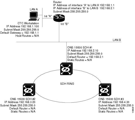
ONS15600SDH nodes use the OSPF protocol in internal ONS15600SDH networks for node discovery, circuit routing, and node management. You can enable OSPF on the ONS15600SDH nodes so that the ONS15600SDH topology is sent to OSPF routers on a LAN. Advertising the ONS15600SDH network topology to LAN routers means you do not need to manually enter static routes for ONS15600SDH subnetworks. Figure8-7 shows the same network enabled for OSPF. When you are logged into an ONS15600SDH node, CTC does not allow both a DCC interface and a LAN interface in the same nonzero OSPF area.
Figure 8-7 Scenario 6: OSPF Enabled
Figure8-8 shows the same network without OSPF. Static routes must be manually added to the router in order for CTC computers on LAN A to communicate with Nodes 2 and 3 because these nodes reside on different subnets.
Figure 8-8 Scenario 6: OSPF Not Enabled
OSPF divides networks into smaller regions, called areas. An area is a collection of networked end systems, routers, and transmission facilities organized by traffic patterns. Each OSPF area has a unique ID number, known as the area ID, that can range from 0 to 4,294,967,295. Every OSPF network has one backbone area called "area 0." All other OSPF areas must connect to area 0.
When you enable ONS15600SDH OSPF topology for advertising to an OSPF network, you must assign an OSPF area ID in decimal format to the ONS15600SDH network. Coordinate the area ID number assignment with your LAN administrator. All DCC-connected ONS15600SDH nodes should be assigned the same OSPF area ID.
The ONS15600SDH supports the multiple OSPF area feature, which allows the ability to configure and support multiple OSPF areas in each DCC-connected topology. A node is in a single OSPF area if all of its DCC or LAN interfaces are in the same OSPF area, while a node is in multiple OSPF areas if it has DCC or LAN interfaces in two or more OSPF areas. If the 15600SDH has interfaces (DCC or LAN) in multiple OSPF areas, at least one ONS15600SDH interface (DCC or LAN) must be in the backbone area 0.
If multiple ONS15600SDH nodes and routers are connected to the same LAN in OSPF backbone area0 and a link between two routers breaks, the backbone OSPF area 0 could divide into multiple gateway network elements (GNEs). If this occurs, the CTC session connected to Router 1 will not be able to communicate with the ONS15600SDH connected to Router 2. To resolve, you must repair the link between the routers or provide another form of redundancy in the network. This is standard behavior for an OSPF network.
Note
Note
8.2.7 Scenario 7: Provisioning the ONS 15600 SDH Proxy Server
The ONS15600SDH proxy server is a set of functions that allows you to configure ONS15600SDH nodes in environments where visibility and accessibility between ONS15600SDH nodes and CTC computers must be restricted. For example, you can set up a network so that field technicians and network operating center (NOC) personnel can both access the same ONS15600SDH nodes while preventing the field technicians from accessing the NOC LAN. To do this, one ONS15600SDH is provisioned as a GNE and the other ONS15600SDH nodes are provisioned as ENEs. The GNE ONS15600SDH tunnels connections between CTC computers and ENE ONS15600SDH nodes, providing management capability while preventing access for non-ONS15600SDH management purposes.
The ONS15600SDH proxy server performs the following tasks:
•
•
•
•
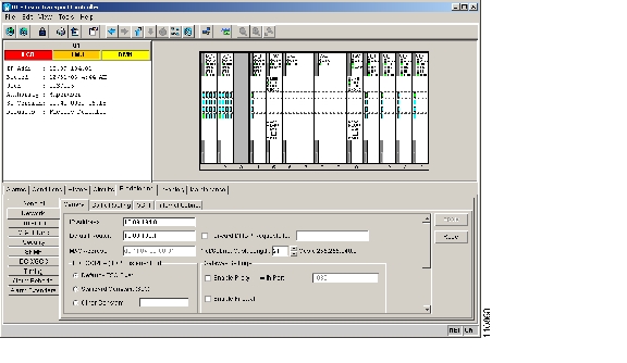
The ONS15600SDH proxy server is provisioned using three check boxes on the Provisioning > Network > General tab (see Figure8-9):
•
Note
•
•
Figure 8-9 Proxy Server Gateway Settings
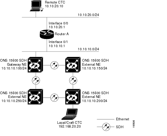
Figure8-10 shows an ONS15600SDH proxy server implementation. A GNE ONS15600 is connected to a central office LAN and to ENE ONS15600SDH nodes. The central office LAN is connected to a NOC LAN, which has CTC computers. The NOC CTC computer and craft technicians must both be able to access the ONS15600SDH ENEs. However, the craft technicians must be prevented from accessing or seeing the NOC or central office LANs.
In the example, the ONS15600SDH GNE is assigned an IP address within the central office LAN and is physically connected to the LAN through its LAN port. ONS15600SDH ENEs are assigned IP addresses that are outside the central office LAN and given private network IP addresses. If the ONS15600SDH ENEs are colocated, the craft LAN ports could be connected to a hub. However, the hub should have no other network connections.
Figure 8-10 Scenario 7: ONS 15600 SDH Proxy Server with GNE and ENEs on the Same Subnet
Table8-2 shows recommended settings for ONS15600SDH GNEs and ENEs in the configuration shown in Figure8-10.
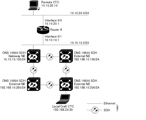
Figure8-11 shows the same proxy server implementation with ONS15600SDH ENEs on different subnets. The ONS15600SDH GNEs and ENEs are provisioned with the settings shown in Table8-2.
Figure 8-11 Scenario 7: ONS 15600 SDH Proxy Server with GNE and ENEs on Different Subnets
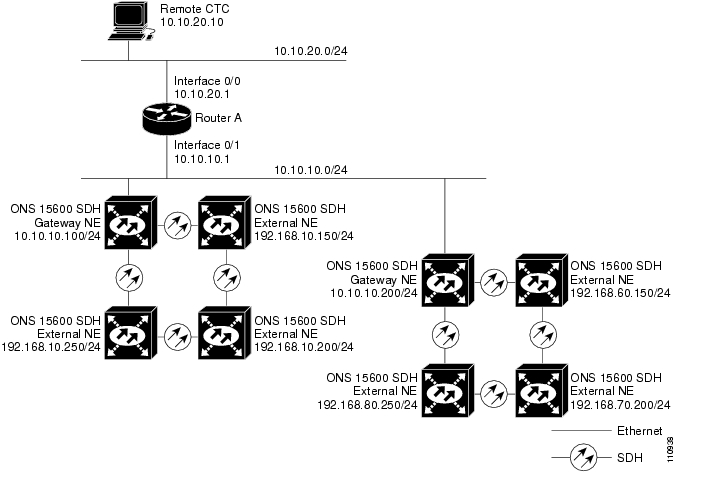
Figure8-12 shows the Figure8-11 implementation with ONS15600SDH ENEs in multiple rings. The ONS15600 GNEs and ENEs are provisioned with the settings shown in Table8-2.
Figure 8-12 Scenario 7: ONS 15600 SDH Proxy Server With ENEs on Multiple Rings
8.2.7.1 Firewall Enabled
Table8-3 shows the rules the ONS15600SDH users to filter packets when the firewall is enabled.
The rules in Table8-4 are applied if a packet is addressed to the ONS15600SDH. Rejected packets are discarded.
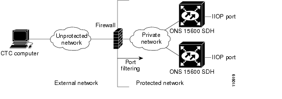
If an ONS15600SDH or CTC computer resides behind a firewall that uses port filtering, you must enable an Internet Inter-ORB Protocol (IIOP) port on the ONS15600SDH and/or CTC computer, depending on whether one or both devices reside behind a firewall. You can enable an IIOP port on the Provisioning>Network>General tabs in CTC.
Figure8-13 shows ONS15600SDH nodes in a protected network and the CTC computer in an external network. For the computer to access the ONS15600SDH nodes, you must provision the IIOP listener port specified by your firewall administrator on the ONS15600SDH. The ONS15600SDH sends the port number to the CTC computer during the initial contact between the devices using HTTP. After the CTC computer obtains the ONS15600SDH IIOP port, the computer opens a direct session with the node using the specified IIOP port.
Figure 8-13 Nodes Behind a Firewall
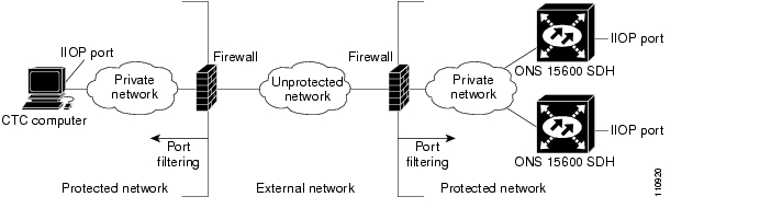
Figure8-14 shows a CTC computer and ONS15600SDH nodes behind firewalls. For the computer to access the ONS15600SDH, you must provision the IIOP port on the CTC computer and on the ONS15600SDH. Each firewall can use a different IIOP port. For example, if the CTC computer firewall uses IIOP port 4000 and the ONS15600SDH firewall uses IIOP port 5000, provision IIOP port 4000 for the CTC computer and provision IIOP port 5000 for the ONS15600SDH.
Figure 8-14 CTC Computer and ONS 15600 SDH Nodes Residing Behind Firewalls
8.2.7.2 Proxy Server Implementation Guidelines
If you implement the proxy server, keep the following cases in mind:
1.
2.
3.
4.
If nodes become unreachable in cases 1, 2, and 3, correct the setting by performing one of the following:
•
•
8.3 Routing Table
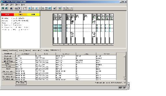
ONS15600SDH routing information appears on the Maintenance > Routing Table tabs ( Figure8-15). The routing table provides the following information:
•
•
•
•
•
–
–
–
–
–
–
Figure 8-15 Viewing the ONS 15600 SDH Routing Table
Table8-5 shows sample routing entries for an ONS15600SDH.
Entry 1 shows the following:
•
•
•
•
Entry 2 shows the following:
•
•
•
•
Entry 3 shows the following:
•
•
•
•
Entry 4 shows the following:
•
•
•
•
Entry 5 shows a DCC-connected node that is accessible through a node that is not directly connected:
•
•
•
•
![]()
![]()
![]()
![]()
![]()
![]()
![]()
![]()
Posted: Thu Feb 26 17:37:18 PST 2004
All contents are Copyright © 1992--2004 Cisco Systems, Inc. All rights reserved.
Important Notices and Privacy Statement.