This chapter provides procedures for connecting PCs and workstations to the Cisco ONS 15454 SDH and starting Cisco Transport Controller (CTC) sessions. It also includes general information about CTC features and functions. Table 2-1 lists procedures for starting CTC. Table 2-2 lists information about learning basic CTC functions. Table 2-3 lists basic CTC features.
CTC is a Java application downloaded from the ONS 15454 SDH Timing Communications and Control (TCC-I) card to your computer when you connect to an ONS 15454 SDH. Launched from a web browser, such as Netscape Navigator or Microsoft® Internet Explorer, CTC allows you to perform ONS 15454 SDH provisioning and administrative functions.
Every time you connect to an ONS 15454 SDH:
A CTC launcher applet downloads from the TCC-I to your browser.
The launcher verifies that your computer has a CTC version matching the version on the ONS 15454 SDH TCC-I.
If the computer does not have CTC, or if the installed version is older than the TCC-I version, the launcher downloads the CTC program files from the TCC-I.
The launcher then starts CTC as a separate application. Each ONS 15454 SDH can run up to four network-level CTC sessions (login node and its DCC-connected nodes) and one node-level session (login node only) at one time.
Note Performance may vary, depending upon the volume of activity in each session.
2.2 Checking Computer Requirements
Requirements for PCs and Solaris workstations are provided in Table 2-4 and Table 2-5.
2.2.1 Check Computer Hardware Requirements
The processor and RAM listed below represent the minimum computer requirements necessary to run CTC.
Table 2-4 Computer Hardware Requirements for CTC
Hardware
Requirements
Notes
Processor
Pentium II 300 MHz (minimum), UltraSPARC, or equivalent
300 Mhz is the recommended processor speed. You can use computers with less processor speed; however, you may experience longer response times and slower performance.
RAM
128 megabytes (minimum)
Hard Drive
2 GB
CTC application files are downloaded from the TCC-I to your computer's Temp directory. These files occupy 3-5 MB of hard drive space.
Operating System
PC: Windows 95, Windows 98, Windows NT, or Windows 2000
Workstation: Solaris 2.6 or 2.7
Cable
User-supplied Category 5 straight-through cable with RJ-45 connectors on each end to connect the computer to the ONS 15454 SDH directly or through a LAN
2.2.2 Check Computer Software Requirements
To use CTC SDH Software R3.3, your computer must have a web browser with the correct Java Runtime Environment (JRE) installed. Both JRE 1.2.2 and JRE 1.3.1_02 are compatible with ONS 15454 SDH Software R3.3, but JRE 1.3.1_02 is recommended.
From the ONS 15454 SDH software or documentation CD install: Netscape Communicator, the JRE, the required Java plug-in and modified java.policy file. See "Running the CTC Setup Wizard" section for detailed information about setting up your computer.
Table 2-5 Computer Software Requirements for CTC
Software
Requirements
Notes
Web browser
PC: Netscape Navigator 4.51 or higher, Netscape Communicator 4.61 or higher, or Internet Explorer 4.0 (service pack 2) or higher
Solaris: Netscape Navigator 4.76 or higher is recommended.
Netscape Communicator 4.73 (Windows) and 4.76 (Solaris) are installed by the CTC Setup Wizard included on the Cisco ONS 15454 SDH software and documentation CDs.
Java Runtime Environment
PC and Solaris:
JRE 1.2.2_05 with Java Plug-in 1.2.2 minimum
JRE 1.3.1_02 (PC and Solaris) recommended
JRE 1.3.1 is installed by the CTC Setup Wizard included on the Cisco ONS 15454 SDH software and documentation CDs.
Java.policy file
A java.policy file modified for CTC must be installed
A modified java.policy file is installed by the CTC Setup Wizard included on the Cisco ONS 15454 SDH software and documentation CDs.
PC mouse pointer scheme
PC: (Windows 95/98) Set to Windows Standard
PC: (Windows NT or Windows 2000) Set to None
To check the settings:
a. Choose Settings > Control Panel from the Windows Start menu.
b. Double-click the Mouse option.
c. From the Pointers tab of the Mouse Properties dialog box, select the Windows Standard (or "none" for NT or Windows 2000) mouse scheme.
d. Click OK.
2.3 Running the CTC Setup Wizard
Cisco ONS 15454 SDH Software R3.3 provides a setup wizard that installs the files needed to use CTC on PCs and Solaris workstations. You can start the setup wizard from the Cisco ONS 15454 SDH software CD or from the Cisco ONS 15454 SDH documentation CD. The wizard will install:
Netscape Communicator 4.73 (Windows) or 4.76 (Solaris)
JRE 1.3.1_02 (Windows & Solaris)
Cisco ONS 15454 SDH CTC online help
Modified java.policy file
For Solaris workstations, the JRE may require patches to operate properly. You can find the patch tar file in the Jre/Solaris directory on the CD. For information about installing the patches, see the Jre/Solaris/Solaris.txt file on the CD. After installing the patches, if necessary, perform the "Set Up the Java Runtime Environment for UNIX" procedure to set up JRE on the workstation. (In the procedures, [JRE] indicates the destination directory you selected for the JRE.).
Procedure: Run the CTC Installation Wizard for Windows
Purpose
Installs programs required to run CTC on Windows PCs: Netscape 4.73, JRE 1.3.1_02, and CTC online help. It also modifies the Java Runtime Environment (JRE) policy file so CTC files can be downloaded to your computer when you connect to an ONS 15454 SDH.
Tools/Equipment
Cisco ONS 15454 SDH R3.3 software or documentation CD
Prerequisite Procedures
None
Onsite/Remote
Onsite or remote
Step 1 Verify that your computer has the following:
Processor—Pentium II, 300 Mhz or faster
RAM—128 MB (minimum)
Hard drive—2 GB is recommended. 50 MB of space must be available.
Operating System—Windows 95, Windows 98, Windows NT 4.0, or Windows 2000
Note These requirements are guidelines. CTC performance will be faster if your computer has a
faster processor and more RAM.
Step 2 Insert the Cisco ONS 15454 SDH R3.3 software or documentation CD into your computer CD drive. The installation program begins running automatically. If it does not start, navigate to your computer's CD directory and double-click setup.exe.
The Cisco Transport Controller Installation Wizard displays the components that will be installed on your computer (Figure 2-1).
Figure 2-1 Starting the Cisco Transport Controller Installation Wizard
Step 3 Click Next.
Step 4 For installation type, choose Typical to install all the components, or choose Custom if you only want to install some of the components.
Step 5 Click Next.
Step 6 If you selected Custom in Step 4, select the CTC components you want to install by checking or unchecking the boxes, then click Next. If you selected Typical, skip this step.
Step 7 The directory where the installation wizard will install CTC online help is displayed. The default is C:\Program Files\Cisco\CTC\Documentation.
Step 8 If you wish to change the CTC online help directory, type the new directory path in the Directory Name field, or click Browse to navigate to the directory. If you do not wish to change the directory, skip this step.
Step 9 Click Next.
Step 10 Review the components that will be installed. If you wish to change them, click Back. If you have an active CTC session (for example, you are running the setup program to install additional components), close CTC before going to the next step.
Step 11 Click Next. The InstallShield program begins the Netscape Communicator 4.73 Setup program.
Step 12 Complete the Netscape installation:
a. On the Netscape Communicator 4.73 Setup dialog box, click Next.
b. On the Software License Agreement dialog box, click Yes.
c. On the Setup Type dialog box, click Typical.
Note If the Netscape installation hangs when installing RealPlayer G2, restart the CTC
installation. When the Netscape installation begins, select Custom at Step
c, then deselect RealPlayer,
then continue.
d. On the Netscape Desktop Preferences dialog box, check the boxes that apply, then click Next.
e. On the Program Folder dialog box, click Next.
f. On the Start Copying Files dialog box, click Install. The program begins the Netscape installation.
g. On the Question dialog box, click No.
h. On the Restart Windows dialog box, click No, I will restart later, then click OK. The Cisco Transport Controller Installation Wizard dialog box is displayed.
a. On the Software License Agreement dialog box, click Yes.
b. On the Choose Destination Location dialog box, click Next.
c. On the Select Browser dialog box, click the Microsoft Internet Explorer and Netscape 6 checkboxes, then click Next.
When JRE installation is complete, the Cisco Transport Controller Installation Wizard dialog box is displayed.
Step 15 Click Next. The CTC online help is installed. When installed, the policy file selection is displayed.
Step 16 Choose the JRE policy file to modify:
Choose User Policy File (default) to modify the policy file that applies only to your user profile. This file will not be overwritten if you upgrade or reinstall the JRE. If you are the only user who will access an ONS 15454 SDH from the PC you are setting up, choose this option.
Select System Policy File to modify the system JRE policy file. This policy file applies to all computer users. If more than one individual will use this computer to access the ONS 15454 SDH, choose this option. However, if you reinstall or upgrade the JRE, the system policy file is overwritten and you will need to run the CTC Installation Setup program again to modify it.
Step 17 Click Next.
Step 18 If you selected System Policy File in Step 16, complete the following steps. If you selected User Policy File, proceed to the next step.
a. The System Policy File Update dialog box displays the default policy file location (C:\Program Files\JavaSoft\jre). If you installed the JRE in a different location, enter the new path in the Directory Name field. After entering the path, or if the default path is correct, click OK.
Procedure: Run the CTC Installation Wizard for UNIX
Purpose
This procedure installs programs required to run CTC on Solaris workstations: Netscape 4.76, JRE 1.3.1_02, and CTC online help. It also modifies the Java Runtime Environment (JRE) policy file to allow CTC files to be downloaded to your computer after you connect to an ONS 15454 SDH.
Tools/Equipment
Cisco ONS 15454 SDH R3.3 software or documentation CD
Prerequisite Procedures
None
Onsite/Remote
Onsite or remote
Step 1 Verify that your computer has the following:
RAM—128 MB (minimum)
Hard drive—Verify that 50 MB of space is available.
Operating System—Solaris 2.5.x or 2.6.x
Note These requirements are guidelines. CTC performance will be faster is your computer has a
faster processor and more RAM. Refer to the Cisco ONS 15454 SDH Troubleshooting and
Maintenance Guide for computer requirements needed for small, medium, and large ONS
15454 SDH networks.
Step 2 Change the directory, type:
cd /cdrom/cdrom0/
Step 3 From the techdoc454 CD directory, type:
./setup.bat
The Cisco Transport Controller Installation Wizard displays the components that will be installed on your computer:
Netscape Communicator 4.76
Java Runtime Environment 1.3.1_02
CTC Online Help
Modify Policy File—the JRE java.policy file is modified to enable CTC to download files needed to run the Cisco Transport Controller when you connect to an ONS 15454 SDH.
Step 4 Click Next.
Step 5 For installation type, choose Typical to install all components, or choose Custom if you do not want to install all of the components.
Step 6 Click Next.
Step 7 If you selected the Custom in Step 4, select the CTC components you want to install by checking or unchecking the boxes, then click Next. If you selected Typical, skip this step.
Step 8 The directory where the installation wizard will install CTC online help is displayed. The default is C:\Program Files\Cisco\CTC\Documentation. If you wish to change the CTC online help directory, type the new directory path in the Directory Name field, or click Browse to navigate to the directory.
Step 9 Click Next.
Step 10 Review the components that will be installed. If you wish to change them, click Back. If CTC is running (for example, you are reinstalling components) close CTC before going to the next step.
Step 11 Click Next. The InstallShield program begins the Netscape Communicator 4.76 Setup program.
Step 12 Complete the Netscape installation:
a. On the Netscape Communicator 4.73 Setup dialog box, click Next.
b. On the Software License Agreement dialog box, click Yes.
c. On the Setup Type dialog box, click Typical.
d. On the Netscape Desktop Preferences dialog box, check the boxes that apply, then click Next.
e. On the Program Folder, click Next.
f. On the Start Copying Files dialog box, click Install. The program begins the Netscape installation.
g. On the Question dialog box, click No.
Step 13 On the Cisco Transport Controller Installation Wizard dialog box, click Next. The Java 2 runtime environment installation begins.
Step 14 Complete the JRE installation:
a. On the Software License Agreement dialog box, click Yes.
b. On the Choose Destination Location dialog box, click Next.
c. On the Select Browser dialog box, click the Netscape 6 checkboxes, then click Next.
The JRE is installed. When installation is complete, the Cisco Transport Controller Set Wizard dialog box is displayed.
Step 15 Click Next. The CTC online help is installed. When installed, the policy file selection is displayed.
Step 16 Choose the JRE policy file to modify:
Choose User Policy File (default) to create a policy file that applies only to your user profile. This file will not be overwritten if you upgrade or reinstall the JRE. If you are the only computer user who will access an ONS 15454 SDH, choose this option.
Select System Policy File to modify the system JRE policy file. This policy file applies to all computer users. If more than one individual will use this computer to access the ONS 15454 SDH, choose this option. However, if you reinstall or upgrade the JRE, the system policy file is overwritten and you will need to run the CTC Installation Setup program again to modify it.
Step 17 Click Next, then click Finish.
Note Be sure to record the names of the directories you choose for Netscape, JRE, and the online
documentation.
Note The Java Runtime Environment (JRE) may require certain patches
to run properly. The patch tar file can be found in the JRE/Solaris directory on the CD. Please
read the JRE/Solaris/Solaris.txt file for more information. In addition to installing any
needed patches, follow the procedures below to set up JRE for use with Cisco Transport
Controller on your UNIX system.
Procedure: Set Up the Java Runtime Environment for UNIX
Purpose
Sets up the Java Runtime Environment for UNIX workstations.
Required if you installed the JRE during the CTC Installation Setup.
Onsite/Remote
Onsite or remote
Note In this procedure, [your JRE path] represents the destination directory you chose for the Java
Runtime Environment during JRE installation. For example, if your JRE destination directory is
/usr/bin/jre, substitute /usr/bin/jre, wherever [your JRE path] occurs. Also, in the following
procedures, [your Netscape path] refers to the destination directory you chose for Netscape, and
must be substituted with your actual Netscape destination directory path.
Note CTC requires that the location of xterm is also in your path. If you have, for some reason, moved
xterm from its default location, /usr/openwin/bin, you must change all occurrences of
/usr/openwin/bin in the procedures below to reflect the actual path where xterm exists on your
system.
Step 1 Set up the environment variable:
a. If you are using the csh shell, edit the .cshrc file in your home directory by appending the file with the lines:
Note If you are running multiple shells, before your new environment
variable will be set you may need to invoke the same shell for which you changed the
initialization file (for example, if you added the environment variable to the .cshrc file, you
must run your browser under the csh shell.
2.4 Setting Up the CTC Computer
Before you run CTC on your Windows PC or Solaris workstation, you need to set up the computer for the specific method you will use to connect to the ONS 15454 SDH. Table 2-6 lists the methods for connecting to the ONS 15454 SDH. Use the table to find the connection method you will use and check the Requirements column before performing the set up procedures.
Note For initial shelf turn up, you must use a direct connection to the ONS 15454 SDH.
Table 2-6 ONS 15454 SDH Connection Methods
Method
Description
Requirement
Local craft
Refers to onsite network connections between the CTC computer and the ONS 15454 SDH using:
The RJ-45 jack on the MIC-C/T/P FMEC, or
A hub or switch to which the ONS 15454 SDH is connected.
If you do not use DHCP, you will need to change the computer IP address, subnet mask, and default router.
Corporate LAN
Refers to a connection to the ONS 15454 SDH through a corporate or NOC LAN.
The ONS 15454 SDH must be provisioned for LAN connectivity, including IP address, subnet mask, default gateway.
The ONS 15454 SDH must be physically connected to the corporate LAN.
The CTC computer must be connected to the corporate LAN that has connectivity to the ONS 15454 SDH.
Remote
Refers to a connection made to the ONS 15454 SDH using a modem.
A modem must be connected to the ONS 15454 SDH.
The modem must be provisioned for ONS 15454 SDH. To run CTC, the modem must be provisioned for Ethernet access.
Based on the cable connection method you choose, select the appropriate procedure:
To set up your computer for local craft connections, choose a procedure from Table 2-7.
Step 1 Verify the operating system that is installed on your computer:
a. From the Windows Start menu, choose Settings > Control Panel.
b. On the Control Panel window, double-click the System icon.
c. On the General tab of the System Settings window, verify that the Windows operating system is one of the following: Windows 95, Windows 98, Windows 2000, or Windows NT 4.0.
Step 2 Complete the steps in Table 2-8 for the operating system installed on your PC.
Table 2-8 Set Up Windows PC for Craft ONS 15454 SDH Connections on the Same Subnet Using Static IP Addresses
For Windows 95/98:
For Windows NT:
For Windows 2000:
1. From the Windows Startmenu, choose Settings > Control Panel.
2. On the Control Panel dialog box, click the Network icon.
3. In the Network dialog box select TCP/IP for your PC Ethernet card, then click Properties.
4. On the TCP/IP Properties dialog box, click the DNS Configuration tab and choose Disable DNS.
5. Click the WINS Configuration tab and choose Disable WINS Resolution.
6. Click the IP Address tab.
7. In the IP Address window, click Specify an IP address.
8. In the IP Address field, enter an IP address that is identical to the ONS 15454 SDH IP address shown on the ONS 15454 SDH LCD except for the last three digits. The last three digits must be between 1 and 254.
9. In the Subnet Maskfield, type 255.255.255.0.
10. Click OK.
11. On the TCP/IP dialog box, click the Gateway tab.
12. In the New Gateway field, type the ONS 15454 SDH IP address. Click Add.
13. Verify that the IP address displays in the Installed Gateways field, then click OK.
14. When the prompt to restart your PC displays, click Yes.
1. From the Windows Startmenu, choose Settings > Control Panel.
2. On the Control Panel dialog box, click the Network icon.
3. In the Network dialog box click the Protocols tab, choose TCP/IP Protocol, then click Properties.
4. Click the IP Address tab.
5. In the IP Address window, click Specify an IP address.
6. In the IP Address field, enter an IP address that is identical to the ONS 15454 SDH IP address shown on the ONS 15454 SDH LCD except for the last three digits. The last three digits must be between 1 and 254.
7. In the Subnet Mask field, type 255.255.255.0.
8. Click the Advanced button.
9. Under the Gateways List, click Add. The TCP/IP Gateway Address dialog box is displayed.
10. Type the ONS 15454 SDH IP address in the Gateway Address field.
11. Click Add.
12. Click OK.
13. Click Apply.
14. In some cases, Windows NT will prompt you to reboot your PC. If you receive this prompt, click Yes.
1. From the Windows Start menu, choose Settings > Network and Dial-up Connections > Local Area Connection.
2. On the Local Area Connection Status dialog box, click Properties.
3. On the General tab, choose Internet Protocol (TCP/IP), then click Properties.
4. Click Use the following IP address.
5. In the IP Address field, enter an IP address that is identical to the ONS 15454 SDH IP address shown on the ONS 15454 SDH LCD except for the last three digits. The last three digits must be between 1 and 254.
6. In the Subnet Mask field, type 255.255.255.0.
7. In the Default Gateway field, type the ONS 15454 SDH IP address.
8. Click OK.
9. On the Local Area Connection Status dialog box, click Close.
10. On the Local Area Connection Properties dialog box, click OK.
Step 1 Verify the operating system that is installed on your computer:
a. From the Windows Start menu, choose Settings > Control Panel.
b. On the Control Panel window, double-click the System icon.
c. On the General tab of the System Settings window, verify that the Windows operating system is one of the following: Windows 95, Windows 98, Windows 2000, or Windows NT 4.0.
Step 2 Complete the steps in Table 2-9 for the operating system installed on your PC.
Table 2-9 Set Up Windows PC for Craft ONS 15454 SDH Connections Using DHCP
For Windows 95/98:
For Windows NT:
For Windows 2000:
1. From the Windows Startmenu, choose Settings > Control Panel.
2. On the Control Panel dialog box, click the Network icon.
3. In the Network dialog box select TCP/IP for your PC Ethernet card, then click Properties.
4. On the TCP/IP Properties dialog box, click the DNS Configuration tab and choose Disable DNS.
5. Click the WINS Configuration tab and choose Disable WINS Resolution.
6. Click the IP Address tab.
7. In the IP Address window, click Obtain an IP address from a DHCP Server.
8. Click OK.
9. When the prompt to restart your PC displays, click Yes.
1. From the Windows Startmenu, choose Settings > Control Panel.
2. On the Control Panel dialog box, click the Network icon.
3. In the Network dialog box click the Protocols tab, choose TCP/IP Protocol, then click Properties.
4. Click the IP Address tab.
5. In the IP Address window, click Obtain an IP address from a DHCP Server.
6. Click OK.
7. Click Apply.
8. If Windows prompts you to restart your PC, click Yes.
1. From the Windows Start menu, choose Settings > Network and Dial-up Connections > Local Area Connection.
2. On the Local Area Connection Status dialog box, click Properties.
3. On the General tab, choose Internet Protocol (TCP/IP), then click Properties.
4. Click Obtain an IP address from a DHCP Server.
5. Click OK.
6. On the Local Area Connection Status dialog box, click Close.
7. On the Local Area Connection Properties dialog box, click OK.
Note This procedure employs the ONS 15454 SDH automatic host detection to allow you to directly
connect to multiple ONS 15454 SDHs successively without reconfiguring your computer's IP
address. However, if proxy server is not enabled on the ONS 15454 SDH, DCC-connected nodes on
different subnets will not be visible. Refer to the
"Setting Up Network Information" section
on and the "Scenario 8:
Provisioning the ONS 15454 SDH Proxy Server" section for more information about
the proxy server.
Step 1 Verify the operating system that is installed on your computer:
a. From the Windows Start menu, choose Settings > Control Panel.
b. On the Control Panel window, double-click the System icon.
c. On the General tab of the System Settings window, verify that the Windows operating system is one of the following: Windows 95, Windows 98, Windows 2000, or Windows NT 4.0.
Step 2 Complete the steps in Table 2-10 for the operating system installed on your PC.
Table 2-10 Set Up Windows PC for Craft ONS 15454 SDH Connections Using Automatic Host Detection
For Windows 95/98:
For Windows NT:
For Windows 2000:
1. From the Windows Startmenu, choose Settings > Control Panel.
2. On the Control Panel dialog box, click the Network icon.
3. In the Network dialog box select TCP/IP for your PC Ethernet card, then click Properties.
4. On the TCP/IP Properties dialog box, click the DNS Configuration tab and choose Disable DNS.
5. Click the WINS Configuration tab and choose Disable WINS Resolution.
6. Click the IP Address tab.
7. In the IP Address window, click Specify an IP address.
8. In the IP Address field, enter a legitimate IP address. This is typically a private address not used by any host accessible to the PC.
9. In the Subnet Maskfield, type 255.255.255.0.
10. Click OK.
11. On the TCP/IP dialog box, click the Gateway tab.
12. In the New Gateway field, type PC IP address (the address entered in Step 8). Click Add.
13. Verify that the IP address displays in the Installed Gateways field, then click OK.
14. When the prompt to restart your PC displays, click Yes.
1. From the Windows Startmenu, choose Settings > Control Panel.
2. On the Control Panel dialog box, click the Network icon.
3. In the Network dialog box click the Protocols tab, choose TCP/IP Protocol, then click Properties.
4. Click the IP Address tab.
5. In the IP Address window, click Specify an IP address.
6. In the IP Address field, enter a legitimate IP address. This is typically a private address not used by any host accessible to the PC.
7. In the Subnet Mask field, type 255.255.255.0.
8. Click the Advanced button.
9. Under the Gateways List, click Add. The TCP/IP Gateway Address dialog box is displayed.
10. Type the IP address entered in Step 6 in the Gateway Address field.
11. Click Add.
12. Click OK.
13. Click Apply.
14. In some cases, Windows NT will prompt you to reboot your PC. If you receive this prompt, click Yes.
1. From the Windows Start menu, choose Settings > Network and Dial-up Connections > Local Area Connection.
2. On the Local Area Connection Status dialog box, click Properties.
3. On the General tab, choose Internet Protocol (TCP/IP), then click Properties.
4. Click Use the following IP address.
5. In the IP Address field, enter a legitimate IP address. This is typically a private address not used by any host accessible to the PC.
6. In the Subnet Mask field, type 255.255.255.0.
7. Type the IP address entered in Step 5 in the Gateway Address field.
8. Click OK.
9. On the Local Area Connection Status dialog box, click Close.
10. On the Local Area Connection Properties dialog box, click OK.
Procedure: Set up Solaris Workstations for a Direct Connection to an ONS 15454 SDH
A direct connection from a workstation to ONS 15454 SDH means your computer is physically connected to the ONS 15454 SDH. Set up Solaris to connect directly to an ONS 15454 SDH when it is not connected to a LAN.
Purpose
Connect your workstation directly to the ONS 15454 SDH.
RJ-45 jack on the ONS 15454 SDH MIC-C/T/P FMEC: Attach a CAT-5 cable from the workstation's NIC card to the RJ-45 jack on the ONS 15454 SDH MIC-C/T/P FMEC.
Hub or switch: Attach a CAT-5 cable from the workstation's NIC card to the RJ-45 jack on a hub or switch to which the ONS 15454 SDH is physically connected.
Step 2 Log into the workstation as the root user.
Step 3 Check to see if the interface is plumbed by typing:
# ifconfig <device>
For example: # ifconfig hme1
a. If the interface is plumbed, a message similar to the following appears: hme1:flags=1000842<BROADCAST,RUNNING,MULTICAST,IPv4>mtu 1500 index 2 inet 0.0.0.0 netmask 0. Proceed to Step 4.
b. If the interface is not plumbed, a message similar to the following appears: ifconfig: status: SIOCGLIFFLAGS: hme1: no such interface. Plumb the interface by typing:
# if config <device> plumb
For example: ifconfig hme1 plumb
Step 4 Configure the IP address on the interface by typing:
#ifconfig <interface> <ip address> netmask <netmask> up
For example: #ifconfig hme0 10.20.30.40 netmask 255.255.255.0 up
Note Enter an IP address that is identical to the ONS 15454 SDH IP address except for the last
three digits. The last three digits must be between 1 and 254. In the Subnet Mask field, type
255.255.255.0.
Step 5 Test the connection:
a. Start Netscape Navigator or Internet Explorer.
b. Enter the Cisco ONS 15454 SDH IP address in the web address (URL) field. If the connection is established, a Java Console window, CTC caching messages, and the Cisco Transport Controller Login dialog box displays. If this occurs, proceed to Step 2 of "Run the CTC Installation Wizard for UNIX" procedure to complete the login. If the Login dialog box does not appear, complete Steps c and d.
c. At the prompt, type:
ping [ONS 15454 SDH IP address]
For example, you would type "ping 192.168.1.1" to connect to an ONS 15454 SDH with default IP address 192.168.1.1. If your workstation is connected to the ONS 15454 SDH, an "[IP address] is alive" message displays.
d. If CTC is not responding, a "Request timed out" message displays. Verify IP and submask information. Check that the cables connecting the workstation to the ONS 15454 SDH are securely attached. Check the Link Status by typing:
#ndd -set /dev/<device> instance 0
#ndd -get /dev/<device> link_status
For example:
#ndd -set /dev/hme instance 0
#ndd -get /dev/hme link_status
The result of 1 means the link is up. The result of 0 means the link is down.
Note Check the man page for ndd. For example: #man ndd
Procedure: Set Up a Computer for a Corporate LAN Connection
Purpose
Use this procedure to set up your computer to access the ONS 15454 SDH through a corporate LAN.
Step 1 If your computer is connected to the corporate LAN, proceed to Step 2. If you changed your computer's network settings for direct access to the ONS 15454 SDH, change the settings back to the corporate LAN access settings. This generally means:
Set the IP Address on the TCP/IP dialog box back to "Obtain an IP address automatically" (Windows 95/98) or "Obtain an IP address from a DHCP server" (Windows NT/2000).
If your LAN requires that DNS or WINS be enabled, change the setting on the DNS Configuration or WINS Configuration tab of the TCP/IP dialog box.
Step 2 If your computer is connected to a proxy server, disable proxy service or add the ONS 15454 SDH nodes as exceptions. To disable proxy service, complete the procedure for the web browser you use:
Procedure: Disable Proxy Service Using Internet Explorer (Windows)
Purpose
Disables proxy service for PCs running Internet Explorer.
Tools/Equipment
None
Prerequisite procedures
None
Onsite/Remote
Onsite or remote
Step 1 From the Start menu, select Settings > Control Panel.
Step 2 In the Control Panel window, choose Internet Options.
Step 3 From the Internet Properties dialog box, click Connections > LAN Settings.
Step 4 On the LAN Settings dialog box, either:
Deselect Use a proxy server to disable the service, or
Leave Use a proxy server selected and click Advanced. On the Proxy Setting dialog box under Exceptions, enter the IP addresses of ONS 15454 SDH nodes that you will access. Separate each address with a semicolon. You can insert an asterisk for the host number to include all the ONS 15454 SDHs on your network. Click OK to close each open dialog box.
Procedure: Disable Proxy Service Using Netscape (Windows and UNIX)
Purpose
Disables proxy service for PCs and UNIX workstations running Netscape.
Tools/Equipment
None
Prerequisite procedures
None
Onsite/Remote
Onsite or remote
Step 1 Open Netscape.
Step 2 From the Edit menu, choose Preferences.
Step 3 In the Preferences dialog box under Category, choose Advanced > Proxies.
Step 4 On the right side of the Preferences dialog box under Proxies, either:
Choose Direct connection to the Internet to bypass the proxy server
or
Choose Manual proxy configuration to add exceptions to the proxy server, then click View. On the Manual Proxy Configuration dialog box under Exceptions, enter the IP addresses of the ONS 15454 SDH nodes that you will access. Separate each address with a comma. Click OK to close each open dialog box.
Procedure: Provision Remote Access to the ONS 15454 SDH
Purpose
Use this procedure to connect an ONS 15454 SDH using a LAN modem.
Step 1 Connect the modem to the RJ-45 port on the MIC-C/T/P FMEC (future use).
Step 2 Refer to the modem documentation to provision the modem for the ONS 15454 SDH:
For CTC access, set the modem for Ethernet access.
Assign an IP address to the modem that is on the same subnet as the ONS 15454 SDH.
The IP address the modem assigns to the CTC computer must be on the same subnet as the modem and the ONS 15454 SDH.
Note For assistance on provisioning specific modems, contact the Cisco Technical Assistance
Center. For contact information refer to the preface in the Product Overview.
2.5 Logging into CTC
Purpose
Use this procedure to log into the CTC. This procedure includes optional node login procedures.
Step 3 As needed, complete the "Create Login Node Groups" procedure. Login node groups display nodes that are not connected to the log-in node via DCC.
Step 1 If your computer is set up for a local craft connection, connect a CAT-5 cable from the PC or Solaris workstation NIC card to one of the following
The RJ-45 port on the MIC-C/T/P FMEC
The RJ-45 port on a hub or switch to which the ONS 15454 SDH is physically connected
Step 2 If your computer is set up for a corporate LAN connection, connect a CAT-5 cable from the PC or Solaris workstation NIC card to a LAN port.
Step 1 From the PC connected to the ONS 15454 SDH, start Netscape or Internet Explorer.
Step 2 In the Netscape or Internet Explorer Web address (URL) field, enter the ONS 15454 SDH IP address. For initial setup, this is the default address, 192.1.0.2. Press Enter.
Note If you are logging into ONS 15454 SDH nodes running different
releases of CTC software, log into the node running the most recent release. If you log into
a node with an older release, you receive an INCOMPATIBLE-SW
alarm and the IP address of the login node will display instead of the node name. To check
the software version of a node, select About CTC from the CTC
Help menu. To resolve an alarm, refer to the Cisco ONS 15454 SDH Troubleshooting and
Maintenance Guide.
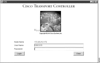
A Java Console window displays the CTC file download status. The web browser displays information about your Java and system environments. If this is the first login, CTC caching messages display while CTC files are downloaded to your computer. The first time you connect to an ONS 15454 SDH, this process can take several minutes. After the download, the CTC Login dialog box displays (Figure 2-2).
Figure 2-2 Starting a CTC Session on the ONS 15454 SDH
Step 3 In the Login dialog box, type a user name and password (both are case sensitive). For initial setup, type the user name "CISCO15" if it is not already displayed.
Note The CISCO15 user is provided with every ONS 15454 SDH. CISCO15 has superuser
privileges, so you can create other users. CISCO15 is delivered without a password. To create
one, click the Provisioning > Security tabs after you log in and change the CISCO15
password. (You cannot delete the CISCO15 user.) To set up ONS 15454 SDH users and
assign security, proceed to the
"Creating Users and Setting
Security" procedure.
Step 4 Each time you log into an ONS 15454 SDH, you can make selections on the following login options:
Node Name—Displays the IP address entered in the web browser and a pull-down menu of previously-entered ONS 15454 SDH IP addresses. You can select any ONS 15454 SDH on the list for the login, or you can enter the IP address (or node name) of any new node where you want to log in.
Additional Nodes—Displays a list of login node groups that were created. To create a login node group or add additional groups, see the "Create Login Node Groups" procedure.)
Exclude Dynamically Discovered Nodes—Check this box to view only the ONS 15454 SDH (and login node group members, if any) entered in the Node Name field. Nodes linked to the Node Name ONS 15454 SDH through the DCC are not displayed. Using this option can decrease the CTC startup time in networks with many DCC-connected nodes.
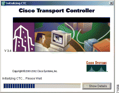
Step 5 Click Login. Figure 2-3 shows the detailed view of a CTC session initializing.
If login is successful, the CTC window displays. From here, you can navigate to other CTC views to provision and manage the ONS 15454 SDH. If you need to perform the initial shelf turn up, see "Node Setup." If login problems occur, refer to the Cisco ONS 15454 SDH Troubleshooting and Maintenance Guide.
Procedure: Create Login Node Groups
Purpose
Create a login node group to display ONS 15454 SDHs that have an IP connection but not a DCC connection to the login node.
Step 1 Log into an ONS 15454 SDH on the network. See the "Log into CTC" procedure for instructions.
Step 2 From the Edit menu, choose Preferences.
Step 3 Click the Login Node Group tab and click Create Group.
Step 4 Enter a name for the group in the Create Login Group Name dialog box. Click OK.
Step 5 Under Members, type the IP address (or node name) of a node you want to add to the group. Click Add. Repeat this step for each node you want to add to the group.
Step 6 Click OK.
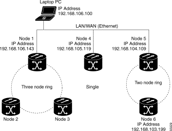
The next time you log into an ONS 15454 SDH, the login node group will be available in the Additional Nodes list of the Login dialog box. For example, in Figure 2-4, a login node group, "Test Group," is created and the IP addresses for Nodes 1, 4, and 5. During login, if you select Test Group under Additional Nodes, all nodes in the figure are displayed. You can create as many login groups as you need. The groups are stored in the CTC preferences file and are not visible to other users.
Figure 2-4 A login node group
Procedure: Add a Node to the Current Session or Login Group
Purpose
Add a node to the current CTC session
Tools
None
Prerequisite procedures
None
Required/As needed
As needed
Onsite/Remote
Onsite or remote
Step 1 Log into an ONS 15454 SDH on the network. See the "Log into CTC" procedure for instructions.
Step 2 From the CTC File menu, click Add Node (or click the Add Node button on the toolbar).
Step 3 On the Add Node dialog box, enter the node name (or IP address).
Step 4 If you want to add the node to the current login group, click Add Node to Current Login Group. Otherwise, leave it unchecked.
Note The Add Node to Current Login Group checkbox is active only if you selected a login group
when you logged into CTC.
Step 5 Click OK.
After a few seconds, the new node will be displayed on the network view map.
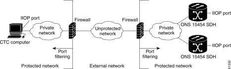
2.6 Accessing ONS 15454 SDH Behind Firewalls
If an ONS 15454 SDH or CTC computer resides behind a firewall that uses port filtering, you must receive an Internet Inter-ORB Protocol (IIOP) port from your network administrator and enable the port on the ONS 15454 SDH and/or CTC computer, depending on whether one or both devices reside behind firewalls.
Note For information about firewall settings using the Provisioning > Network > Gateway Settings feature,
see "IP Networking."
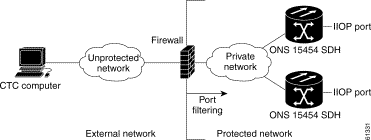
If the ONS 15454 SDH is in a protected network and the CTC computer is in an external network, as shown in Figure 2-5, enable the IIOP listener port specified by the firewall administrator on the ONS 15454 SDH. The ONS 15454 SDH sends the port number to the CTC computer during the initial contact between the devices using Hyper-Text Transfer Protocol (HTTP). After the CTC computer obtains the ONS 15454 SDH IIOP port, the computer opens a direct session with the node using the specified IIOP port.
Figure 2-5 ONS 15454 SDH residing behind a firewall
If the CTC computer and the ONS 15454 SDH both reside behind firewalls (Figure 2-6), set the IIOP port on both the CTC computer and the ONS 15454 SDH. Each firewall can use a different IIOP port.
For example, if the CTC computer firewall uses IIOP port 4000, and the ONS 15454 SDH firewall uses IIOP port 5000, 4000 is the IIOP port set on the CTC computer and 5000 is the IIOP port set on the ONS 15454 SDH.
Figure 2-6 A CTC computer and ONS 15454 SDH residing behind firewalls
Procedure: Set the IIOP Listener Port on the ONS 15454 SDH
IIOP listener port number from LAN or firewall administrator.
Onsite/Remote
Onsite or remote
Step 1 From the CTC Edit menu, select Preferences.
Step 2 On the Preferences dialog box, select the Firewall tab.
Step 3 Under CTC CORBA (IIOP) Listener Port, set the listener port option:
Default - Variable—Used to connect to ONS 15454 SDH from within a firewall or if no firewall is used
Standard Constant (683)—Uses port 683
Other Constant—Allows you to specify an IIOP port defined by your administrator
Step 4 Click Apply to apply the change.
Step 5 Click OK to close the screen.
2.7 Printing CTC Data
You can print CTC windows and table data such as alarms and inventory. You can also export CTC table data for use by other applications such as spreadsheets, word processors, and database management applications.
Procedure: Print CTC Window and Table Data
Purpose
Use the following procedure to print CTC windows and table data. Before you start, make sure your PC is connected to a printer.
Step 2 In the Print dialog (Figure 2-7) choose an option:
Entire Frame—Prints the entire CTC window
Tabbed View—Prints the lower half of the CTC window
Table Contents—Prints CTC data in table format; this option is only available for CTC table data (see Figure 2-7)
Figure 2-7 Selecting CTC data for print
Step 3 Click OK.
Step 4 In the Print dialog box, choose a printer and click OK.
2.8 Exporting CTC Data into Other Applications
CTC data exported in HTML format can be viewed with any web browser, such as Netscape Navigator or Microsoft Internet Explorer. To display the data, use the browser's File/Open command to open the CTC data file.
CTC data exported as comma separated values (CSV) or tab separated values (TSV) can be viewed in text editors, word processors, spreadsheets, and database management applications. Although procedures depend on the application, you typically can use File/Open to display the CTC data. Text editors and word processors display the data exactly as it is exported. Spreadsheet and database management applications display the data in cells. You can then format and manage the data using the spreadsheet or database management application tools.
In addition to the CTC exporting, CTC text information can be copied and pasted into other applications using the Windows Copy (Ctrl+C), Cut (Ctrl+X) and Paste (Ctrl+V) commands.
Procedure: Export CTC Data
Purpose
Use the following procedure to export CTC data for use in other applications.
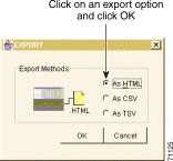
Step 2 In the Export dialog (Figure 2-8) choose a format for the data:
As HTML—Saves the data as an HTML file. The file can be viewed with a web browser without starting CTC.
As CSV—Saves the CTC table values as text, separated by commas. You can import CSV data into spreadsheets and database management programs.
As TSV—Saves the CTC table values as text, separated by tabs. You can import TSV data into spreadsheets and database management programs.
Figure 2-8 Selecting CTC data for export
Step 3 Click OK.
Step 4 In the Save dialog box, enter a file name in one of the following formats:
[filename].htm for HTML files.
[filename].csv for CSV files.
[filename].tsv for TSV files.
Step 5 Navigate to a directory where you want to store the file.
Step 6 Click Save.
2.9 Using the Node View
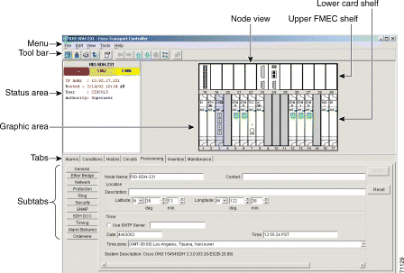
CTC has three main ONS 15454 SDH views: node, network, and card view. The CTC node view, shown in Figure 2-9, displays when you start a CTC session on an ONS 15454 SDH. The login node is the first node displayed, and it is the "home view" for the session.
Node view allows you to view and manage one ONS 15454 SDH node. The status area shows the node name, IP address, session boot date and time, number of critical (CR), major (MJ), and minor (MN) alarms, the name of the current user, and security level of the user. The graphic area depicts the ONS 15454 SDH FMECs and cards in the shelf assembly.
The CTC window displays when you start a CTC session on an ONS 15454 SDH (Figure 2-9). The window includes a menu bar, toolbar, status area, and a graphic area displaying the upper and lower node shelves.
The upper shelf displays status information about the selected objects and a graphic of the current view. The lower shelf displays tabs and subtabs, that you use to view ONS 15454 SDH information and perform ONS 15454 SDH provisioning and maintenance.
Figure 2-9 CTC window elements in the node view (default session view)
2.9.1 Node View Card Color and Graphic Definitions
The graphic area of the CTC window depicts the ONS 15454 SDH shelf assembly. The colors of the FMECS, cards, Act/Standby/NP, and ports in the graphic reflect the real-time status of the physical FMECs, cards, slots, and ports (Table 2-12). FMECs cannot be pre-provisioned and the FMEC ports displayed in CTC do not change color.
Table 2-12 Node View FMEC Color, Card Color, Port Color, and Port Graphics
Upper Shelf FMEC Color
Status
White
A functioning card is installed
Yellow
A minor alarm condition exists
Orange (Amber)
A major alarm condition exists
Red
A critical alarm exists
Lower Shelf Card Color
Status
Grey
Slot is not provisioned; no card is installed
Violet
Slot is provisioned; no card is installed
White
Slot is provisioned; a functioning card is installed
Yellow
Slot is provisioned; a minor alarm condition exists
Orange (Amber)
Slot is provisioned; a major alarm condition exists
Red
Slot is provisioned; a critical alarm exists
Lower Shelf Act/Sty/NP/Ldg Color
Status
Yellow with Sty Graphic
The card is in standby.
Green with Act Graphic
The card is active.
Violet with NP Graphic
The card is not present.
White with Ldg Graphic
The card is resetting.
Lower Shelf Port Color
Status
Grey
Port is out of service
Green
Port is in service
Lower Shelf Port Graphics
Status
Multiple diagonal lines on port
Port is in service and card was reset
Loop graphic on port
Port is in service and has a loopback provisioned in Card View > Maintenance > Loopback
2.9.2 Node View Card Shortcuts
If you move your mouse over FMECs in the upper shelf of the graphic, tooltips displays the equipment FMEC card type. If you move your mouse over cards in the lower shelf in the graphic, tooltips displays additional information about the card including the card type, card status (active or standby), the number of critical, major, and minor alarms (if any), and the alarm profile used by the card. Right-clicking a card reveals a shortcut menu, which you can use to open, reset, or delete a card. Right-click a slot (grey) to pre-provision a card in the lower shelf (i.e., provision a slot before installing the card in the lower shelf).
Note The FMECs in the upper shelf cannot be pre-provisioned.
Note CTC software does not monitor for the presence or absence of FMECs unless the TCC-I(s) card has
reached the active/standby state. During transitional states such as power-up or TCC-I reset CTC
ignores the FMEC inventory displayed in node view.
Procedure: Add a Node to the Current Session
Purpose
During a CTC session, you can add nodes that are not displayed in the session without having to log out of the session. When you add the node, you have the option to add it to the current login node group.
Step 1 From the CTC File menu, click Add Node (or click the Add Node button on the toolbar).
Step 2 On the Add Node dialog box, enter the node name (or IP address).
Step 3 If you want to add the node to the current login group, click Add Node to Current Login Group. Otherwise, leave it unchecked.
Step 4 Click OK.
After a few seconds, the new node will be displayed on the network view map.
2.9.3 Check Inventory from the Node View
The Inventory tab (Figure 2-10) displays information about cards installed in the ONS 15454 SDH node including location, equipment type, hardware part numbers, hardware revisions, and serial numbers. The Inventory tab provides information about ONS 15454 SDH Product Change Notices (PCNs) and Field Service Bulletins (FSBs). Using the ONS 15454 SDH export feature, you can export inventory data from ONS 15454 SDH nodes into spreadsheet and database programs to consolidate ONS 15454 SDH information for network inventory management and reporting.
Figure 2-10 Displaying ONS 15454 SDH hardware information
The Inventory tab displays the following information about the cards installed in the ONS 15454 SDH:
Location—The slot where the card is installed
Eqpt Type—Equipment type the slot is provisioned for, for example, STM-4 or E-1
Actual Eqpt Type—The actual card that is installed in the slot, for example, STM4 SH 1310 or E1N-14
Tip You can pre-provision a slot before the card is installed by right-clicking the slot in node view and selecting a card type. FMECs, located in the upper shelf, cannot be pre-provisioned.
HW Part #—Card part number; this number is printed on the top of the card
HW Rev—Card revision number
Serial #—Card serial number; this number is unique to each card
CLEI Code—Common Language Equipment Identifier code
Firmware Rev—Revision number of the software used by the ASIC chip installed on the card
2.9.4 View CTC Software Versions on One Node
CTC software is pre-loaded on the ONS 15454 SDH TCC-I cards; therefore, you do not need to install software on the TCC-I. When a new CTC software version is released, you must follow procedures provided by the Cisco Technical Assistance Center (TAC) to upgrade the ONS 15454 SDH software.
When you upgrade CTC software, the TCC-I stores the older CTC version as the protect CTC version, and the newer CTC release becomes the working version. To view software versions on the network, see the "View CTC Software Versions on the Network" section.
In the CTC node view, click the Maintenance > Software tabs.
When you upgrade CTC software, the TCC-I stores the older CTC version as the protect CTC version, and the newer CTC release becomes the working version.
Figure 2-11 Viewing software versions
2.9.5 Node View Tabs
Use the node view tabs and subtabs, shown in Table 2-13, to provision and manage the ONS 15454 SDH.
Table 2-13 Node View Tabs and Subtabs
Tab
Description
Subtabs
Alarms
Lists current alarms (CR, MJ, MN) for the node and updates them in real-time
—
Conditions
Displays a list of standing conditions on the node.
—
History
Provides a history of node alarms including date, type, and severity of each alarm.
Session, Node: The Session subtab displays alarms and events for the current session. The Node subtab displays alarms and events retrieved from a fixed-size log on the node.
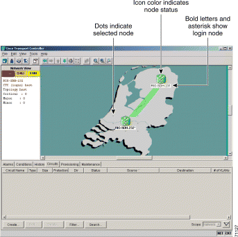
Network view (Figure 2-12) allows you to view and manage ONS 15454 SDH that have DCC connections to the node running the CTC session and any login node groups you may have selected. (Nodes optically-connected to the login node will not display if you selected Exclude Dynamically Discovered Nodes on the Login dialog box.)
The graphic area displays a background image with colored ONS 15454 SDH icons. The icon colors indicate the node status (Figure 2-12). Green lines show DCC connections between the nodes. Selecting a node or span in the graphic area displays information about the node and span in the status area.
Figure 2-12 A two-node network displayed in CTC network view
2.10.1 Network View Node Color Definitions
The colors of nodes displayed in network view show alarm status.
Table 2-14 Node Status in Network View
Color of Node Icon
Alarm Status
Green
No alarms
Yellow
Minor alarms
Orange (Amber)
Major alarms
Red
Critical alarms
Grey with node name
Node is initializing
Grey with IP address
Node is initializing, or a problem exists with IP routing from node to CTC
Table 2-15 Network View User Options from the Node Icon
Action
Procedure
When you right-click a node icon, or use the Ctrl key you can perform these actions:
Open a node
Any of the following:
Double-click a node icon
Right-click a node icon, choose Open Node from the shortcut menu
Click a node and from the View menu choose Go to Selected Object View
From the View menu, choose Go toOther Node. Select a node from the Select Node dialog box
Double-click a node alarm or event in the Alarms or History tabs
Reset the default node icon position
Right-click a node and choose Reset Node Position from the shortcut menu. The node icon moves to the position defined by the longitude and latitude fields set in node view on the Provisioning > General tabs.
Right-click a node and choose Update Circuits With New Node from the shortcut menu. Use this command when you add a new node and want to pass circuits through it.
Move a node icon
Press the Ctrl key and the left mouse button simultaneously and drag the node icon to a new location.
Table 2-16 Network View User Options from the Span Icon
Action
Procedure
Display span properties
Any of the following:
Move mouse over a span; properties display above the span
Click a span; properties display in the upper left corner of the window
Right-click a span; properties display at the top of the shortcut menu
When you right-click a span (straight lines between nodes), you can perform these actions:
Perform an SNCP protection switch for an entire span
Right-click a network span and click Circuits. See "Perform SNCP Span Switching" for SNCP span switching procedures.
Upgrade a span
Right-click a span and choose Span Upgrade from the shortcut menu.
Note For detailed span upgrade information and instructions, refer to the Cisco ONS 15454 SDH Troubleshooting and Maintenance Guide.
Display a link end point
Right-click a span. On the shortcut menu, select Go To [node/slot/port] for the drop port you want to view. CTC displays the card in card view.
Table 2-17 Network View User Options from the Graph Menu
Action
Procedure
When you right-click a map or background image you can perform these actions:
Right-click on the map in the background and choose Center Graph
Click and drag the vertical and horizontal scroll bars framing the map image
Click the arrow buttons at the ends of the vertical and horizontal scroll bars framing the map image
Stretch the map to fit into the network view window
Right-click on the map in the background and choose Fit Graph to Window.
Reset map to default view
Right-click on the map in the background and choose Reset Zooming (1:1).
Enlarge the map
Any of the following:
Click the Zoom In icon
Right-click on the map in the background and choose Zoom In
Reduce the map size
Any of the following:
Click the Zoom Out icon
Right-click on the map in the background and choose Zoom Out
Enlarge a selected area of the map
Any of the following:
Click theZoom Selected Area icon. Left-click the desired start point on the map and drag the mouse to the desired end point of the map and release the mouse.
Right-click on the map in the background and choose Zoom Selected Area. Left-click the desired start point on the map and drag the mouse to the desired end point of the map and release the mouse.
Change the color behind the map image
Right-click on the map in the background and choose Set Background Color. The Choose Color menu appears with three tabs: Swatches, HSB, and RGB. Make a selection using your mouse, then click OK. For more information, see the "Modify the Network or Domain Background Color" procedure.
Set a user-defined background image
Right-click on the map or image in the background and choose Set Background Image. From the menu, select any JPEG or GIF image that is accessible on a local or network drive. For more information, see the "Change the Network View Background Image" procedure.
Remove a map or user-defined background image
Right-click on the map or image in the background and choose Remove Background Image.
Procedure: Create and Manage Domains in the Network View
Purpose
Domains are groups of ONS 15454 SDHs displayed as icons on the network view map. Adding domains to the network view map makes networks with many nodes easier to manage. After you create a domain, you can drag and drop ONS 15454 SDH icons into it (Figure 2-14). The ONS 15454 SDHs are hidden until you open the domain. Figure 2-15 shows an example of an opened domain. You must have super user login access to create, delete, or rename a domain, add a node to a domain, or remove a node from a domain.
Note Domains you create will be seen by all CTC users on the network. When you create a domain
and add a node, other CTC users may see the node disappear momentarily from the network
view. Also, when the domain view is open, CTC switches to the network view if the domain
is removed by another CTC user.
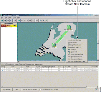
Step 1 Right-click the network map and choose Create New Domain from the shortcut menu. When the domain icon appears on the map, type the domain name.
Figure 2-13 Creating a domain
Step 2 Drag a node icon to the domain icon. Release the mouse button when the node icon is over the domain icon. Repeat this step for each node you want to add to the domain.
After you add a node to a domain, the span lines leading to nodes within the domain become thicker. The thick lines may represent multiple spans. The thick line is green if all spans it represents are active, and grey if any one span it represents has errors. The domain icon color reflects the highest alarm severity of any node within it. For node color and alarm status, see Table 2-14.
Figure 2-14 Adding nodes to a domain
Step 3 Open the domain by double-clicking the domain icon, or right-clicking the domain and choose Open Domain. Verify the selected nodes are within the domain as shown in Figure 2-15.
Within the domain, external nodes and domains that are directly connected to nodes inside the domain are displayed in a dimmed color. DCC links with one or two ends inside the domain are also displayed.
Figure 2-15 Nodes displayed within the domain
Step 4 Right-click the domain view area and choose Go to Parent View from the shortcut menu to return to the network view.
You manage ONS 15454 SDH nodes that reside within a domain the same way you manage ONS 15454 SDH nodes on the network map. Table 2-18 shows the domain actions.
Table 2-18 Managing Domains
Action
Procedure
A domain must be created before the following domain menu options are available:
Move a domain
Pressing Ctrl, drag the domain icon to the new location.
Move a node out of a domain back to the network map
From the domain view, right-click a node and choose Move Node Back to Parent View.
When you right-click a domain you can perform these actions:
Open a domain
Right-click the domain icon and choose Open Domain.
Show domain overview
Right-click the domain icon and choose Show Domain Overview. The domain icon shows a small preview of the nodes in the domain. To turn off the domain overview, select Show Domain Overview again.
Rename a domain
Right-click the domain icon and choose Rename Domain from the shortcut menu. Type the new name in the domain name field.
Remove domain
Right-click the domain icon and choose Remove Domain. Any nodes residing in the domain are returned to the network map.
Procedure: Modify the Network or Domain Background Color
Purpose
You can change the color of the background for the network view and the domain view (the area displayed when you open a domain). If you modify background colors, the change is stored in your CTC user profile on the computer. The change does not affect other CTC users.
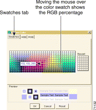
Step 1 From the network view, right-click the domain map area or background color and choose Set Background Color from the shortcut menu.
Step 2 On the Choose Color dialog box, select the Swatches, HSB, or RGB tab.
Swatches—Displays small color samples in a box (Figure 2-16). Click on the color sample to display a preview of the color in the lower portion of the Choose Color dialog box, When you have made your selection, click OK.
Figure 2-16 Choosing a swatch from the Color Menu
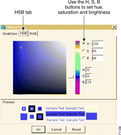
HSB—Allows you to change the hue, saturation, and brightness of your background color (Figure 2-17). Click a color on the color map. Click the H, S, or B button. Use the scroll bar to display the full range of the selected color for hue, saturation, or brightness depending on the button selected. For example, click on B then drag the scroll bar up and down. A lighter and then darker version of the selected color displays in the preview area shown in the lower portion of the Choose Color dialog box. After making your selection, click OK.
Figure 2-17 Choosing hue, saturation, or brightness from the Color Menu
RGB—Displays RGB percentages from 0 to 255 (Figure 2-18). Click and drag the red, blue, or green percentage bar to create the desired color or enter a number in the field next to the bar. Check your selection in the preview area shown in the lower portion of the Choose Color dialog box, then click OK.
Figure 2-18 Choosing red, blue, or green from the Color Menu
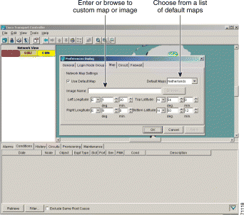
Procedure: Change the Network View Background Image
Purpose
You can replace the background map image displayed in network view with any JPEG or GIF image that is accessible on a local or network drive. If you want to position nodes on the map based on the node coordinates, you will need the longitudes and latitudes for the edges of the map. However, if you will use your mouse to position nodes, coordinates for the image edges are not necessary. The change does not affect other CTC users.
Caution Before you begin this procedure, verify that the image file you want to use is located on your hard drive and is in JPEG or GIF format. CTC may stop responding in the Network view or Circuit tab if you link to a file that is not JPEG or GIF, or if you provide an incorrect path.
Step 1 In network view, choose Edit > Preferences.(You can also right-click the network or domain map and select Set Background Image.)
Step 2 On the General tab of the Preferences dialog box (Figure 2-19) you can:
Uncheck Use Default Map and click Browse. Navigate to the graphic file you want to use as a background. Select the file. Click Open.
or
Choose a new default map from the menu. There are 6 default map options: Germany, Japan, Netherlands, South Korea, United Kingdom, and United States.
Figure 2-19 Changing the background image from the Preferences Dialog screen
Step 3 (Optional) Enter the coordinates for the map image edges in the longitude and latitude fields on the Preferences dialog box. CTC uses the map's longitude and latitude to position the node icons based on the node coordinates entered for each node on the Provisioning > General tabs. Coordinates only need to be precise enough to place ONS node icons in approximate positions on the image. You can also drag and drop nodes to position them on the network view map.
Step 4 Click Apply and then click OK.
Step 5 At the network view, use the CTC toolbar Zoom buttons (or right-click the graphic area and select a Zoom command from the shortcut menu) to set the area of the image you can view.
2.10.3 View CTC Software Versions on the Network
CTC software is pre-loaded on the ONS 15454 SDH TCC-I cards; therefore, you do not need to install software on the TCC-I. When a new CTC software version is released, you must follow procedures provided by the Cisco Technical Assistance Center (TAC) on the web at http://www.cisco.com/public/support/tac/home.shtml to upgrade the ONS 15454 SDH software.
When you upgrade CTC software, the TCC-I stores the older CTC version as the protect CTC version, and the newer CTC release becomes the working version. To view software versions on one node, see the "View CTC Software Versions on One Node" procedure.
In the CTC network view, click the Maintenance >Software tabs.
When you upgrade CTC software, the TCC-I stores the older CTC version as the protect CTC version, and the newer CTC release becomes the working version.
2.11 Using the Card View
Card view (Figure 2-20) displays information about individual ONS 15454 SDH cards. Use this view to perform card-specific maintenance, provisioning, and performance monitoring. A graphic of the selected card is shown in the graphic area. The status area displays the node name, slot, number of alarms, equipment type, and card status—Active, Not Present, or Failed—for the card. The information that is displayed and the actions you can perform depend on the card.
Note CTC displays a card view for all ONS 15454 SDH cards except the FMECS, TCC-I, and XC10G
cards.
Figure 2-20 CTC card view showing a DS3i card
2.11.1 Card View Card and Port Color Definitions
The graphic area of the CTC window depicts the ONS 15454 SDH shelf assembly. The colors of the card and port(s) in the graphic reflect the real-time status of the physical card and port(s) (Table 2-19).
Table 2-19 Card View Card and Port Colors
Upper Shelf FMEC Color
Status
N/A
FMECs do not display a card view
Lower Shelf Card Color in Card View
Status
White
A functioning card is installed
Yellow
A minor alarm condition exists with the card
Orange (Amber)
A major alarm condition exists with the card
Red
A critical alarm condition exists with the card
Port Color
Status
Grey
Port is out of service
Green
Port is in service
Note Port graphics showing loopbacks and card resets do not appear on the card view
level. Proceed to node view to see special port graphics.
2.11.2 Card View Card Shortcuts
If you move your mouse over the port graphic, tooltips displays additional information about the port including the port status (active or standby), and the alarm profile. Right-clicking the card view graphic reveals a shortcut menu, which you can use to go to the parent view (node view).
2.11.3 Card View Tabs
Use the card view tabs and subtabs, shown in Table 2-20, to provision and manage the ONS 15454 SDH.
Table 2-20 Card View Tabs and Subtabs
Tab
Description
Subtabs
Alarms
Lists current alarms (CR, MJ, MN) for the card and updates them in real-time
—
Conditions
Displays a list of standing conditions on the card
—
History
Provides a history of card alarms including date, object, port, and severity of each alarm.
Session, Card: The Session subtab displays alarms and events for the current session. The Card subtab displays alarms and events retrieved from a fixed-size log on the card.
Circuits
Create, delete, edit, and search circuits
—
Provisioning
Provision an ONS 15454 SDH card
Line, Thresholds (different threshold options are available for electrical and optical cards), VC4 or SDH Thresholds, Alarm Behavior
Maintenance
Perform maintenance tasks for the card
Loopback, Info, Protection
Performance
Perform performance monitoring for the card
—
2.12 Navigating CTC
Different navigational methods are available within the CTC window to access views and perform management actions. Commands on the View menu and CTC toolbar allow you to quickly move between network, node, and card views. You can double-click and right-click objects in the graphic area and move the mouse over nodes, cards, and ports to view popup status information (Figure 2-21).
Figure 2-21 CTC node view showing popup information
Different methods for navigating within the CTC window are described in Table 2-21.
Table 2-21 CTC Window Navigation
Technique
Description
View menu and Toolbar
Provide commands to display:
The previous view (available after you navigate to two or more views)
The next view (available after you navigate to previous views)
The parent of the currently-selected view. Network is the parent of node view; node view is the parent of card view.
The currently selected object. For example, selecting a card on the node view graphic displays the card in card view; selecting a node on the network view map displays the node in node view.
Home view (the node you initially logged into)
Network view
Other node (View menu only)
Different zoom levels (toolbar only)
Double-Click
A node in network view displays the node in node view
A card in node view displays the card in card view
Right-Click
Network view graphic area—Displays a menu where you can create a new domain, change the position and zoom level of the graphic image, and change the background image and color.
Node in network view—Displays a menu where you can open the node, provision circuits, update circuits with a new node, and reset the node icon position to the longitude and latitude set on the Provisioning > General tabs.
Span in network view—Displays a menu where you can view information about the source and destination ports, the span's protection scheme, and the span's optical or electrical level. You can also display the Circuits on Span dialog box, which displays additional span information and allows you to perform SDH SNCP protection switching.
Card in node view—Displays a menu where you can open, delete, reset, and change cards. The card that is selected determines the commands that are displayed.
Move Mouse Cursor
Over node in network view—Displays a summary of node alarms and provides a warning if the node icon has been moved out of the map range.
Over span in network view—Displays circuit (node, slot, port) and protection information
Over card in node view—Displays card type and card status
Over card port in node view—Displays port number and port status
2.13 Viewing CTC Table Data
Much of the ONS 15454 SDH data that CTC displays, such as alarms, alarm history, circuits, and inventory, is displayed in tables. You can change the way the CTC tables are displayed. For example, you can:
Rearrange or hide table columns.
Sort tables by primary and secondary keys in descending or ascending order. (Sorting and hiding is available for all read-only tables.)
To change the display of a CTC table, left-click or right-click a column header in the table. Right-click a column header to display a shortcut menu that has table column display options (Figure 2-22).
Figure 2-22 Table shortcut menu that customizes table appearance
Table 2-22 lists the options that you can use to customize information display in CTC tables.
Table 2-22 Table Display Options
Task
Click
Right-Click Shortcut Menu
Resize column
Drag header separator to the right or left
—
Rearrange column order
Drag column header to the right or left
—
When you right-click a column header you can perform these actions:
Reset sorting
—
Choose Reset Sorting
Sort table (primary)
Click a column header; each click changes sort order (ascending or descending)
Choose Sort Column
Sort table (secondary sorting keys)
Press the Shift key and simultaneously click the column header
Choose Sort Column (incremental)
Hide column
—
Choose Hide Column
Display a hidden column
—
Choose Show Column > [Num or Ref]
Revert to default columns
—
Choose Use Default Columns Order/Visibility
Reset column order & display all hidden columns
—
Choose Reset Columns Order/Visibility
View table row count
—
Choose Row count; it is the last item on the shortcut menu