|
|

Table Of Contents
3.2 Class 1 Laser Safety Labels
3.2.1 Class 1 Laser Product Label
3.2.3 Laser Source Connector Label
3.3.2 OSCM Card-Level Indicators
3.3.3 OSCM Port-Level Indicators
3.4.2 OSC-CSM Card-Level Indicators
3.4.3 OSC-CSM Port-Level Indicators
Optical Service Channel Cards
This chapter describes the optical service channel (OSC) cards for Cisco ONS 15454 dense wavelength division multiplexing (DWDM) networks. For installation and card turn-up procedures, refer to the Cisco ONS 15454 DWDM Procedure Guide. For card safety and compliance information, refer to the Cisco Optical Transport Products Safety and Compliance Information document.
Note
Unless otherwise specified, "ONS 15454" refers to both ANSI and ETSI shelf assemblies.
Chapter topics include:
3.1 Card Overview
This section provides card summary and compatibility information.
Note
An optical service channel (OSC) is a bidirectional channel connecting two adjacent nodes in a DWDM ring. For every DWDM node (except terminal nodes), two different OSC terminations are present, one for the west side and another for the east side. The channel transports OSC overhead that is used to manage ONS 15454 DWDM networks. An OSC signal uses the 1510-nm wavelength and does not affect client traffic. The primary purpose of this channel is to carry clock synchronization and orderwire channel communications for the DWDM network. It also provides transparent links between each node in the network. The OSC is an OC-3/STM-1 formatted signal.
There are two versions of the OSC modules: the OSCM, and the OSC-CSM, which contains the OSC wavelength combiner and separator component in addition to the OSC module.
The Mesh/Multiring Upgrade (MMU) card is used to optically bypass a given wavelength from one section of the network or ring to another one without requiring 3R regeneration.
3.1.1 Card Summary
Table 3-1 lists and summarizes the functions of each card.
Table 3-1 OSCM, OSC-CSM, and MMU Card Summary
The OSCM has one set of optical ports and one Ethernet port located on the faceplate. It operates in Slots 8 and 10.
See the "OSCM Card" section.
The OSC-CSM has three sets of optical ports and one Ethernet port located on the faceplate. It operates in Slots 1 to 6 and 12 to 17.
See the "OSC-CSM Card" section.
3.1.2 Card Compatibility
Table 3-2 lists the CTC software compatibility for the OSC and OSCM cards.
Table 3-2 Software Release Compatibility for Optical Service Channel Cards
OSCM
Yes
Yes
Yes
Yes
Yes
Yes
Yes
OSC-CSM
Yes
Yes
Yes
Yes
Yes
Yes
Yes
3.2 Class 1 Laser Safety Labels
This section explains the significance of the safety labels attached to the OSCM and OSC-CSM cards. The faceplates of the cards are clearly labeled with warnings about the laser radiation levels. You must understand all warning labels before working on these cards.
3.2.1 Class 1 Laser Product Label
The Class 1 Laser Product label is shown in Figure 3-1.
Figure 3-1 Class 1 Laser Product Label
Class 1 lasers are products whose irradiance does not exceed the Maximum Permissible Exposure (MPE) value. Therefore, for Class 1 laser products the output power is below the level at which it is believed eye damage will occur. Exposure to the beam of a Class 1 laser will not result in eye injury and may therefore be considered safe. However, some Class 1 laser products may contain laser systems of a higher Class but there are adequate engineering control measures to ensure that access to the beam is not reasonably likely. Anyone who dismantles a Class 1 laser product that contains a higher Class laser system is potentially at risk of exposure to a hazardous laser beam
3.2.2 Hazard Level 1 Label
The Hazard Level 1 label is shown in Figure 3-2.
Figure 3-2 Hazard Level Label
The Hazard Level label warns users against exposure to laser radiation of Class 1 limits calculated in accordance with IEC60825-1 Ed.1.2.
3.2.3 Laser Source Connector Label
The Laser Source Connector label is shown in Figure 3-3.
Figure 3-3 Laser Source Connector Label
This label indicates that a laser source is present at the optical connector where the label has been placed.
3.2.4 FDA Statement Label
The FDA Statement label is shown in Figure 3-4.
Figure 3-4 FDA Statement Label
This label shows compliance to FDA standards and that the hazard level classification is in accordance with IEC60825-1 Am.2 or Ed.1.2.
3.2.5 Shock Hazard Label
The Shock Hazard label is shown in Figure 3-5.
Figure 3-5 Shock Hazard Label
This label alerts personnel to electrical hazard within the card. The potential of shock hazard exists when removing adjacent cards during maintenance, and touching exposed electrical circuitry on the card itself.
This section describes the optical service channel cards. An optical service channel (OSC) is a bidirectional channel connecting two adjacent nodes in a DWDM ring. For every DWDM node (except terminal nodes), two different OSC terminations are present, one for the west side and another for the east side. The channel transports OSC overhead that is used to manage ONS 15454 DWDM networks. An OSC signal uses the 1510-nm wavelength and does not affect client traffic. The primary purpose of this channel is to carry clock synchronization and orderwire channel communications for the DWDM network. It also provides transparent links between each node in the network. The OSC is an OC-3/STM-1 formatted signal.
There are two versions of the OSC modules: the OSCM, and the OSC-CSM, which contains the OSC wavelength combiner and separator component in addition to the OSC module.
3.3 OSCM Card
Note
The OSCM card is used in amplified nodes that include the OPT-BST, OPT-BST-E, or OPT-BST-L booster amplifier. The OPT-BST, OPT-BST-E, and OPT-BST-L cards include the required OSC wavelength combiner and separator component. The OSCM cannot be used in nodes where you use OC-N/STM-N cards, electrical cards, or cross-connect cards. The OSCM uses Slots 8 and 10, which are also cross-connect card slots.
The OSCM supports the following features:
•
•
•
•
•
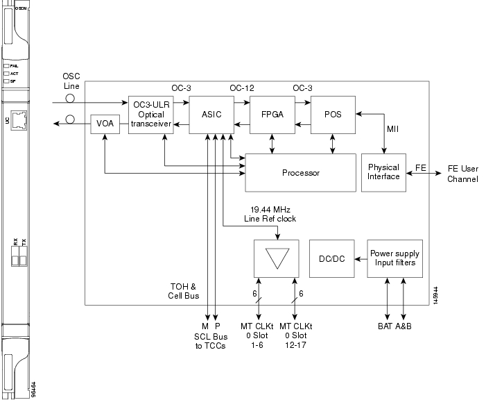
The OC-3/STM-1 section data communications channel (SDCC or RS-DCC) overhead bytes are used for network communications. An optical transceiver terminates the OC-3/STM-1, then it is regenerated and converted into an electrical signal. The SDCC or RS-DCC bytes are forwarded to the active and standby TCC2/TCC2P cards for processing through the system communication link (SCL) bus on the backplane. Orderwire bytes (E1, E2, F1) are also forwarded via the SCL bus to the TCC2/TCC2P for forwarding to the AIC-I card.
The payload portion of the OC-3/STM-1 is used to carry the fast Ethernet UC. The frame is sent to a packet-over-SONET/SDH (POS) processing block that extracts the Ethernet packets and makes them available at the RJ-45 connector.
The OSCM distributes the reference clock information by removing it from the incoming OC-3/STM-1 signal and then sending it to the DWDM cards. The DWDM cards then forward the clock information to the active and standby TCC2/TCC2P cards.
Figure 3-6 shows the OSCM card faceplate and block diagram.
Figure 3-6 OSCM Card Faceplate
For information on safety labels for the card, see the "Class 1 Laser Safety Labels" section.
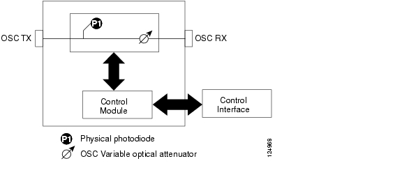
Figure 3-7 shows the block diagram of the variable optical attenuator (VOA) within the OSCM.
Figure 3-7 OSCM VOA Optical Module Functional Block Diagram
3.3.1 Power Monitoring
Physical photodiode P1 monitors the power for the OSCM card. The returned power level value is calibrated to the OSC TX port ( Table 3-3).
Table 3-3 OSCM VOA Port Calibration
P1
Output OSC
OSC TX
3.3.2 OSCM Card-Level Indicators
The OSCM card has three card-level LED indicators, described in Table 3-4.
3.3.3 OSCM Port-Level Indicators
You can find the status of the card ports using the LCD screen on the ONS 15454 fan-tray assembly. Use the LCD to view the status of any port or card slot; the screen displays the number and severity of alarms for a given port or slot. The OSCM has one OC-3/STM-1 optical port located on the faceplate. One long-reach OSC transmits and receives the OSC to and from another DWDM node. Both DCN data and FE payload are carried on this link.
3.4 OSC-CSM Card
Note
The OSC-CSM card is used in unamplified nodes. This means that the booster amplifier with the OSC wavelength combiner and separator is not required for OSC-CSM operation. The OSC-CSM can be installed in Slots 1 to 6 and 12 to 17. To operate in hybrid mode, the OSC-CSM cards must be accompanied by cross-connect cards. The cross-connect cards enable functionality on the OC-N/STM-N cards and electrical cards.
The OSC-CSM supports the following features:
•
•
•
•
•
•
•
•
•
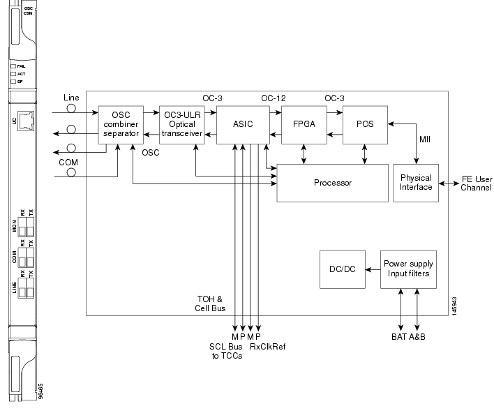
The WDM signal coming from the line is passed through the OSC combiner and separator, where the OSC signal is extracted from the WDM signal. The WDM signal is sent along with the remaining channels to the COM port (label on the front panel) for routing to the OADM or amplifier units, while the OSC signal is sent to an optical transceiver.
The OSC is an OC-3/STM-1 formatted signal. The OC-3/STM-1 SDCC or RS-DCC overhead bytes are used for network communications. An optical transceiver terminates the OC-3/STM-1, and then it is regenerated and converted into an electrical signal. The SDCC or RS-DCC bytes are forwarded to the active and standby TCC2/TCC2P cards for processing via the SCL bus on the backplane. Orderwire bytes (E1, E2, F1) are also forwarded via the SCL bus to the TCC2/TCC2P for forwarding to the AIC-I card.
The payload portion of the OC-3/STM-1 is used to carry the fast Ethernet UC. The frame is sent to a POS processing block that extracts the Ethernet packets and makes them available at the RJ-45 front panel connector.
The OSC-CSM distributes the reference clock information by removing it from the incoming OC-3/STM-1 signal and then sending it to the active and standby TCC2/TCC2P cards. The clock distribution is different from the OSCM card because the OSC-CSM does not use Slot 8 or 10 (cross-connect card slots).
Note
Figure 3-8 shows the OSC-CSM faceplate.
Figure 3-8 OSC-CSM Faceplate
For information on safety labels for the card, see the "Class 1 Laser Safety Labels" section.
Figure 3-9 shows a block diagram of the OSC-CSM card.
Figure 3-9 OSC-CSM Block Diagram
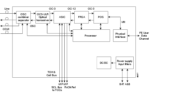
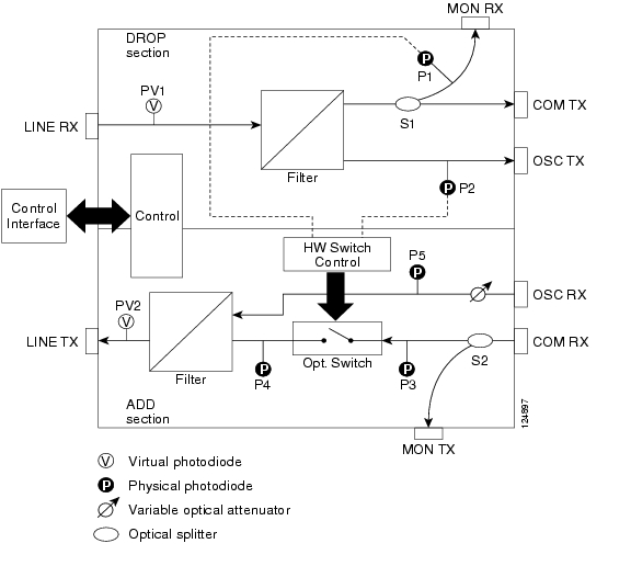
Figure 3-10 shows the OSC-CSM optical module functional block diagram.
Figure 3-10 OSC-CSM Optical Module Functional Block Diagram
3.4.1 Power Monitoring
Physical photodiodes P1, P2, P3, and P5 monitor the power for the OSC-CSM card. Their function is as follows:
•
•
•
The returned power level values are calibrated to the ports as shown in Table 3-5.
Table 3-5 OSC-CSM Port Calibration
P1
Out Com
LINE RX
P2
Input OSC
LINE RX
P3
In Com
COM RX
P5
Output Osc
LINE TX
3.4.2 OSC-CSM Card-Level Indicators
The OSC-CSM card has three card-level LED indicators, described in Table 3-6.
3.4.3 OSC-CSM Port-Level Indicators
You can find the status of the card ports using the LCD screen on the ONS 15454 fan-tray assembly. Use the LCD to view the status of any port or card slot; the screen displays the number and severity of alarms for a given port or slot. The OSC-CSM has a OC3 port and three other sets of ports located on the faceplate.
![]()
![]()
![]()
![]()
![]()
![]()
![]()
![]()
Posted: Mon Oct 22 05:53:06 PDT 2007
All contents are Copyright © 1992--2007 Cisco Systems, Inc. All rights reserved.
Important Notices and Privacy Statement.