|
|

Table Of Contents
NTP-G51 Verify DWDM Node Turn Up
NTP-G52 Verify Node-to-Node Connections
DLP-G95 Set Up External or Line Timing
DLP-G96 Set Up Internal Timing
DLP-G350 Use the Cisco MetroPlanner Traffic Matrix Report
NTP-G54 Provision and Verify a DWDM Network
NTP-G142 Perform a Protection Switch Test
NTP-G164 Configure Link Management Protocol
DLP-G373 Create LMP Control Channels
DLP-G378 Create LMP Data Links
NTP-G57 Create a Logical Network Map
Turn Up a Network
This chapter explains how to turn up and test a Cisco ONS 15454 dense wavelength division multiplexing (DWDM) network. For DWDM topology reference information and span loss tables, refer to the "Network Reference" chapter in the Cisco ONS 15454 DWDM Reference Manual.
There are two main DWDM network types: metro core, where the channel power is equalized and dispersion compensation is applied, and metro access, where the channels are not equalized and dispersion compensation is not applied. The DWDM network topologies supported are hubbed rings, multihubbed rings, meshed rings, linear configurations, and single-span links. The DWDM node types supported are hub, terminal, optical add/drop multiplexing (OADM), reconfigurable optical add/drop multiplexing (ROADM), anti-amplified spontaneous emissions (anti-ASE), and line amplifier. For DWDM and hybrid node turn-up procedures, see Chapter 3, "Turn Up a Node."
Note
Unless otherwise specified, "ONS 15454" refers to both ANSI and ETSI shelf assemblies.
Before You Begin
This section lists the chapter procedures (NTPs). Turn to a procedure for applicable tasks (DLPs).
1.
2.
3.
4.
5.
6.
7.
8.
NTP-G51 Verify DWDM Node Turn Up
Step 1
Step 2
a.
b.
Step 3
•
•
Step 4
Step 5
Step 6
Step 7
Step 8
Step 9
Stop. You have completed this procedure.
NTP-G52 Verify Node-to-Node Connections
Note
Step 1
Step 2
•
•
Step 3
Step 4
Step 5
Step 6
Stop. You have completed this procedure.
NTP-G53 Set Up Timing
Purpose
This procedure provisions the ONS 15454 timing.
Tools/Equipment
None
Prerequisite Procedures
Required/As Needed
Required
Onsite/Remote
Onsite or remote
Security Level
Provisioning or higher
Step 1
Step 2
Step 3
Step 4
Stop. You have completed this procedure.
DLP-G95 Set Up External or Line Timing
Step 1
Step 2
•
•
Note
•
•
•
Step 3
Note
•
–
–
–
•
Note
Step 4
Step 5
Note
Step 6
•
•
Step 7
•
•
•
•
Step 8
•
•
Step 9
•
•
•
•
Step 10
Note
Step 11
DLP-G96 Set Up Internal Timing
Caution
Step 1
Step 2
•
•
•
•
•
Step 3
•
–
–
–
•
Step 4
Step 5
Step 6
Step 7
Step 8
DLP-G350 Use the Cisco MetroPlanner Traffic Matrix Report
Purpose
This task describes how to use the Cisco MetroPlanner traffic matrix report to provision and verify a DWDM network.
Tools/Equipment
None
Prerequisite Procedures
NTP-G139 Verify Cisco MetroPlanner Reports and Files, page 3-3
Required/As Needed
As needed
Onsite/Remote
Onsite
Security Level
Provisioning or higher
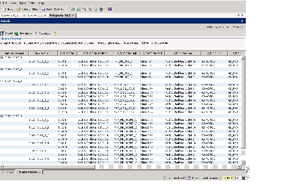
Step 1
Figure 6-1 Cisco MetroPlanner Traffic Matrix Report
Step 2
•
•
•
•
•
•
•
•
•
•
•
•
•
•
•
•
–
–
•
•
–
–
•
Note
•
•
–
–
•
Step 3
NTP-G54 Provision and Verify a DWDM Network
Purpose
This procedure verifies the performance of all cable connections and cards in a network topology. You can also use this procedure to troubleshoot any problems with DWDM network set up.
Tools/Equipment
Test set or protocol analyzer
Cisco MetroPlanner Traffic Matrix
Prerequisite Procedures
G277 Provision a Multirate PPM
G278 Provision the Optical Line Rate
G96 Provision the 10G Multirate Transponder Card Line Settings, PM Parameters, and Thresholds
G97 Modify the 4x2.5G Muxponder Card Line Settings and PM Parameter Thresholds
G98 Provision the 2.5G Multirate Transponder Card Line Settings and PM Parameter Thresholds
G99 Modify the 2.5G Data Muxponder Card Line Settings and PM Parameter Thresholds
G148 Modify the 10G Data Muxponder Card Line Settings and PM Parameter Thresholds
Required/As Needed
As needed
Onsite/Remote
Onsite or remote
Security Level
Provisioning or higher
Note
Step 1
Step 2
a.
b.
Step 3
Step 4
•
•
.After creating the OCHCC or OCHNC circuit, return to this procedure and continue with Step 5.
Note
Step 5
Step 6
Step 7
Step 8
Step 9
a.
b.
c.
–
–
–
d.
Step 10
a.
b.
c.
–
–
–
d.
Step 11
a.
b.
–
–
–
c.
–
–
If the value is not present, skip this step and continue with Step d.
d.
e.
f.
Note
g.
h.
i.
j.
k.
Note
l.
m.
Step 12
a.
b.
c.
d.
e.
Note
f.
Step 13
a.
b.
c.
d.
e.
f.
g.
–
–
Step 14
a.
b.
c.
d.
e.
Note
Note
Step 15
Step 16
Step 17
Step 18
•
•
Step 19
Step 20
Step 21
Step 22
•
•
For all the remaining nodes, no further checks are needed.
Step 23
After all tests are successfully completed and no alarms exist in the network, the network is ready for service.
Stop. You have completed this procedure.
NTP-G56 Verify the OSNR
Step 1
Step 2
Note
Step 3
Note
Step 4
Note
•
•
•
•
If the OSNR is still too low, contact your next level of support.
Step 5
Stop. You have completed this procedure.
NTP-G142 Perform a Protection Switch Test
Step 1
Step 2
Step 3
a.
b.
c.
Step 4
Step 5
Step 6
Step 7
a.
b.
Step 8
Step 9
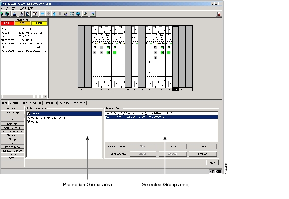
Step 10
Figure 6-2 Maintenance > Protection Tabs
Step 11
Step 12
Step 13
a.
–
–
b.
–
–
Step 14
Step 15
Step 16
a.
–
–
b.
–
–
Step 17
a.
–
–
b.
–
–
Step 18
Note
Step 19
Step 20
Stop. You have completed this procedure.
NTP-G164 Configure Link Management Protocol
Note
Step 1
Step 2
Step 3
Step 4
Step 5
Stop. You have completed this procedure.
DLP-G372 Enable LMP
Step 1
Step 2
Step 3
Step 4
Note
Step 5
Cisco ONS 15454 DWDM node, ensure that the LMP-WDM check box is unchecked.Step 6
•
•
The role selection is only available when LMP-WDM is enabled on the local node. Both the local and remote nodes must be configured with LMP-WDM enabled.
Step 7
Step 8
Step 9
DLP-G373 Create LMP Control Channels
Step 1
Step 2
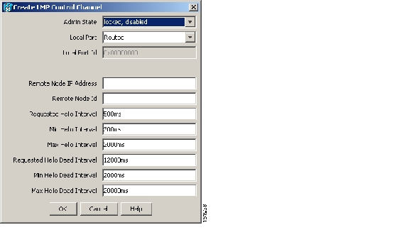
Note
Figure 6-3 Create LMP Control Channel Dialog Box
Step 3
•
•
•
•
•
Note
•
•
•
•
Note
•
Note
•
Note
Step 4
Step 5
Note
Step 6
•
•
•
Note
•
Step 7
Step 8
Step 9
DLP-G374 Create LMP TE Links
Step 1
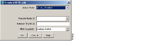
Step 2
Figure 6-4 Create LMP TE Link Dialog Box
Step 3
•
•
•
•
Step 4
Step 5
Step 6
•
•
•
Step 7
Step 8
Step 9
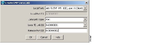
DLP-G378 Create LMP Data Links
Purpose
This task creates, edits, or deletes one or more data links, which define the node's transport parameters. CTC supports up to 256 LMP data links.
Tools/Equipment
None
Prerequisite Procedures
G54 Provision and Verify a DWDM Network
Required/As Needed
As needed
Onsite/Remote
Onsite or remote
Security Level
Provisioning or higher
Note
Step 1
Step 2
Figure 6-5 Create LMP Data Link Dialog Box
Step 3
•
•
•
•
•
Step 4
Step 5
Step 6
•
•
Step 7
Step 8
Step 9
NTP-G57 Create a Logical Network Map
Step 1
Step 2
Step 3
a.
b.
Step 4
Step 5
CTC opens a progress bar and saves the new node positions.
Note
Stop. You have completed this procedure.
![]()
![]()
![]()
![]()
![]()
![]()
![]()
![]()
Posted: Mon Oct 29 01:30:24 PDT 2007
All contents are Copyright © 1992--2007 Cisco Systems, Inc. All rights reserved.
Important Notices and Privacy Statement.