|
|

Table Of Contents
NTP-G139 Verify Cisco MetroPlanner Reports and Files
NTP-G22 Verify Common Card Installation
NTP-G144 Provision a Multishelf Node
NTP-G23 Create Users and Assign Security
DLP-G54 Create a New User on a Single Node
DLP-G55 Create a New User on Multiple Nodes
NTP-G24 Set Up Name, Date, Time, and Contact Information
NTP-G25 Set Battery Power Monitor Thresholds
NTP-G26 Set Up CTC Network Access
NTP-G194 Set Up the ONS 15454 in Secure Mode
DLP-G439 Provision the Designated SOCKS Servers
DLP-G57 Set the IP Address, Default Router, and Network Mask Using the LCD
DLP-G264 Enable Node Security Mode
DLP-G59 Set Up or Change Open Shortest Path First Protocol
DLP-G60 Set Up or Change Routing Information Protocol
NTP-G27 Set Up the ONS 15454 for Firewall Access
DLP-G61 Provision the IIOP Listener Port on the ONS 15454
DLP-G62 Provision the IIOP Listener Port on the CTC Computer
DLP-G283 Provision OSI Routing Mode
DLP-G284 Provision the TARP Operating Parameters
DLP-G285 Add a Static TID-to-NSAP Entry to the TARP Data Cache
DLP-G287 Add a TARP Manual Adjacency Table Entry
DLP-G288 Provision OSI Routers
DLP-G289 Provision Additional Manual Area Addresses
DLP-G290 Enable the OSI Subnet on the LAN Interface
DLP-G291 Create an IP-Over-CLNS Tunnel
NTP-G143 Import the Cisco MetroPlanner NE Update Configuration File
DLP-G353 Preprovision a Single Slot
NTP-G30 Install the DWDM Cards
DLP-G348 Use the Cisco MetroPlanner Shelf Layout Report
NTP-G31 Install the DWDM Dispersion Compensating Units
NTP-G179 Install the TXP, MXP, GE_XP, 10GE_XP, and ADM-10G Cards
DLP-G273 Preprovision an SFP or XFP Slot
NTP-G123 Install the Filler Cards
NTP-G34 Install Fiber-Optic Cables on DWDM Cards and DCUs
DLP-G349 Use the Cisco MetroPlanner Internal Connections Report
NTP-G140 Install Fiber-Optic Cables Between Terminal, Hub, or ROADM Nodes
DLP-G427 Reroute Fiber-Optic Cables in the 40-Channel Patch-Panel Tray
NTP-G185 Install Fiber-Optic Cables between Mesh Nodes
NTP-G191 Install Fiber-Optic Cables on Passthrough ROADM Nodes
NTP-G141 Install Fiber-Optic Cables for Y-Cable Protection Modules
DLP-G375 Install Fiber-Optic Cables on the Y-Cable Modules in the FlexLayer Shelf
DLP-G376 Install Fiber-Optic Cables on the Y-Cable Modules in the Y-Cable Module Tray
NTP-G152 Create and Verify Internal Patchcords
DLP-G354 Create an Internal Patchcord Manually
DLP-G355 Delete an Internal Patchcord
NTP-G38 Provision OSC Terminations
NTP-G37 Run Automatic Node Setup
NTP-G39 Verify OSCM and OSC-CSM Transmit Power
DLP-G313 Verify OSC-CSM Transmit Power
DLP-G314 Verify OSCM Transmit Power
NTP-G163 Upgrade Nodes in Single-Shelf Mode to Multishelf Mode
Turn Up a Node
This chapter explains how to provision a single Cisco ONS 15454 dense wavelength division multiplexing (DWDM) node and turn it up for service, including assigning the node name, date, and time; provisioning timing references; provisioning network attributes such as IP address and default router; setting up users and user security; installing cards; and creating DWDM connections.
Note
Procedures in this chapter require that you have a network plan calculated for your DWDM network with Cisco MetroPlanner, Release 8.0. Cisco MetroPlanner is a DWDM planning tool that is available from your Cisco account representative. Cisco MetroPlanner prepares a shelf plan for each network node and calculates the power and attenuation levels for the DWDM cards installed in the node. For information about Cisco MetroPlanner, contact your Cisco account representative. For instructions on using Cisco MetroPlanner, refer to the Cisco MetroPlanner DWDM Operations Guide, Release 8.0.
Note
Note
Before You Begin
This section lists the non-trouble procedures (NTPs) needed to turn up a DWDM node. Turn to an NTP for applicable detail-level procedures (DLPs), known as tasks.
1.
2.
3.
4.
5.
6.
7.
8.
9.
10.
11.
12.
13.
14.
15.
16.
17.
18.
19.
20.
21.
22.
23.
24.
25.
NTP-G139 Verify Cisco MetroPlanner Reports and Files
Step 1
•
•
Table 3-1 Cisco MetroPlanner Node Setup Information and Files
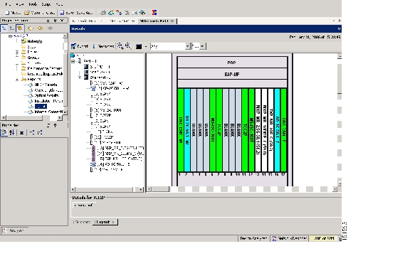
Shelf layout
JPG file
Cisco MetroPlanner provides a shelf layout ( Figure 3-1) showing the cards that should be installed in each ONS 15454 slot. Cisco MetroPlanner can export this as a JPG file with a user-defined name.
Installation Parameters
Table
Provides the target reference values for the variable optical attenuators (VOAs), output power, optical thresholds, and amplifier configuration parameters.
Internal Connections
Table
Identifies the patchcords that must be installed within the shelf.
NE Update Configuration file
XML file
The Cisco MetroPlanner NE Update configuration file is an electronic file with an XML extension and a name assigned by the network designer for the network you are provisioning. The file is imported into CTC where it preprovisions the shelf and configures the following card parameters: OTN and FEC parameters for TXP, MXP, GE_XP, 10GE_XP, ADM-10G cards, card mode for OPT-AMP-L, OPT-AMP-17-C, GE_XP and 10GE_XP cards. It also provisions the OCH trunk to OCH filter internal patchcords, the optical sides. and it configures the ANS parameters based on the network calculated by Cisco MetroPlanner.
Traffic Matrix
Table
Shows the traffic flow within the node. During node turn-up, this report is used to identify the location of Y-cable protection groups.
Cable list
Table or list
A list of cables needed to provision the node. The list can be derived from the Internal Connections Report or from the Bill of Materials report prepared by Cisco MetroPlanner.
Figure 3-1 Cisco MetroPlanner Shelf Layout
If you not do not have all the reports and files listed in Table 3-1, do not continue. See your site or network planner for the required information and files.
Step 2
Stop. You have completed this procedure.
NTP-G22 Verify Common Card Installation
Step 1
Step 2
Step 3
Note
Step 4
Note
Step 5
•
•
Step 6
Note
Stop. You have completed this procedure.
NTP-G144 Provision a Multishelf Node
Purpose
This procedure provisions a multishelf node from CTC. A multishelf node consists of a control node and subtending shelves that are configured to operate as a single node.
Tools/Equipment
None
Prerequisite Procedures
G22 Verify Common Card Installation
NTP-G145 Connect a Multishelf Node and Subtending Shelves to an MS-ISC-100T Card, page 1-82 or
NTP-G158 Connect a Multishelf Node and Subtending Shelves to a Catalyst 2950, page 1-84
Required/As Needed
As needed
Onsite/Remote
Onsite or remote
Security Level
Superuser only
Caution
Step 1
Step 2
a.
b.
c.
•
•
d.
e.
f.
Note
Step 3
a.
b.
c.
d.
e.
f.
g.
h.
i.
j.
k.
l.
m.
n.
Stop. You have completed this procedure.
NTP-G23 Create Users and Assign Security
Step 1
Note
Step 2
Note
Step 3
Stop. You have completed this procedure.
DLP-G54 Create a New User on a Single Node
Purpose
This task creates a new user for one ONS 15454.
Tools/Equipment
None
Prerequisite Procedures
Required/As Needed
As needed
Onsite/Remote
Onsite or remote
Security Level
Superuser only
Step 1
Step 2
Step 3
•
•
Note
•
•
Note
Step 4
Step 5
DLP-G55 Create a New User on Multiple Nodes
Purpose
This task adds a new user to multiple ONS 15454 nodes.
Tools/Equipment
None
Prerequisite Procedures
Required/As Needed
As needed
Onsite/Remote
Onsite or remote
Security Level
Superuser only
Note
Step 1
Step 2
Step 3
Step 4
•
•
•
•
Note
Step 5
Step 6
Step 7
Step 8
NTP-G24 Set Up Name, Date, Time, and Contact Information
Step 1
Step 2
Step 3
Note
Step 4
Step 5
Step 6
CTC uses the latitude and longitude to position ONS 15454 icons on the network view map. To convert a coordinate in degrees to degrees and minutes, multiply the number after the decimal by 60. For example, the latitude 38.250739 converts to 38 degrees, 15 minutes (0.250739 x 60 = 15.0443, rounded to the nearest whole number).
Step 7
Step 8
a.
–
–
Note
Caution
b.
•
•
Step 9
Step 10
Note
Step 11
Step 12
Step 13
Stop. You have completed this procedure.
NTP-G25 Set Battery Power Monitor Thresholds
Caution
Note
Step 1
Step 2
Note
Step 3
Step 4
Step 5
Step 6
Step 7
Stop. You have completed this procedure.
NTP-G26 Set Up CTC Network Access
Step 1
Step 2
Tip
Step 3
Note
Step 4
Step 5
Step 6
Step 7
•
•
•
Stop. You have completed this procedure.
NTP-G194 Set Up the ONS 15454 in Secure Mode
Step 1
Step 2
Step 3
Step 4
Note
Step 5
Stop. You have completed this procedure.
DLP-G56 Provision IP Settings
Caution
Step 1
Step 2
•
Note
•
•
Note
•
–
–
–
•
–
–
–
•
Note
•
Note
•
•
–
–
–
Note
Step 3
Step 4
Both TCC2/TCC2P cards reboot one at a time if changes were made to the IP address, subnet mask, or gateway settings. During this time (approximately 5 to 6 minutes), the active and standby TCC2/TCC2P card LEDs will blink, turn on, and turn off at different intervals. Eventually, a "Lost node connection, switching to network view" message appears.
Step 5
Step 6
Step 7
DLP-G439 Provision the Designated SOCKS Servers
Note
Note
Note
Note
Step 1
Step 2
Step 3
Step 4
Step 5
Step 6
•
•
•
•
Step 7
Step 8
Step 9
DLP-G57 Set the IP Address, Default Router, and Network Mask Using the LCD
Note
Note
Step 1
Step 2
•
•
•
Figure 3-2 Selecting the IP Address Option
Step 3
Figure 3-3 Changing the IP Address
Step 4
Tip
Step 5
Step 6
Step 7
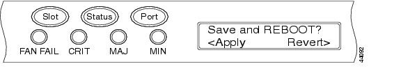
Figure 3-4 Selecting the Save Configuration Option
Step 8
A Save and REBOOT message appears ( Figure 3-5).
Figure 3-5 Saving and Rebooting the TCC2/TCC2P
Step 9
Note
Step 10
Step 11
DLP-G264 Enable Node Security Mode
Purpose
This task enables the ONS 15454 security mode. When security mode is enabled, two IP addresses are assigned to the node. One address is assigned to the backplane LAN port and the other to the TCC2P RJ-45 TCP/IP (LAN) port. The TCC2 card does not support security mode.
Tools/Equipment
TCC2P cards must be installed.
Prerequisite Procedures
NTP-G103 Back Up the Database, page 13-2
Required/As Needed
As needed
Onsite/Remote
Onsite or remote
Security Level
Superuser only
Note
Note
Caution
Note
Step 1
Step 2
Step 3
Step 4
Step 5
Step 6
Step 7
Step 8
•
•
Note
Step 9
Within the next 30 to 40 seconds, the TCC2P cards reboot. CTC switches to network view, and the CTC Alerts dialog box appears. In network view, the node changes to gray and a DISCONNECTED condition appears in the Alarms tab.
Step 10
Step 11
a.
b.
c.
d.
e.
Note
Step 12
DLP-G58 Create a Static Route
Step 1
Step 2
Step 3
•
•
•
•
Step 4
Note
Step 5
DLP-G59 Set Up or Change Open Shortest Path First Protocol
Step 1
Step 2
•
ANSI Nodes
•
•
ETSI Nodes
•
•
Step 3
•
•
Step 4
a.
b.
•
•
•
c.
The authentication button label changes to Simple Password.
Step 5
•
•
•
•
•
•
Step 6
Note
a.
b.
•
•
•
•
c.
Step 7
a.
b.
•
•
•
•
•
•
c.
Step 8
If you changed the Area ID, the TCC2/TCC2P cards reset, one at a time. The reset takes approximately 10 to 15 minutes.
Step 9
DLP-G60 Set Up or Change Routing Information Protocol
Step 1
Step 2
Step 3
Step 4
Step 5
a.
b.
•
•
•
c.
The authentication button label changes to Simple Password.
Step 6
a.
b.
•
•
•
c.
Step 7
NTP-G27 Set Up the ONS 15454 for Firewall Access
Step 1
Step 2
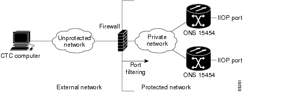
Figure 3-6 shows ONS 15454 nodes in a protected network and the CTC computer in an external network. For the computer to access the ONS 15454 nodes, you must provision the IIOP listener port specified by your firewall administrator on the ONS 15454.
Figure 3-6 Nodes Behind a Firewall
Step 3
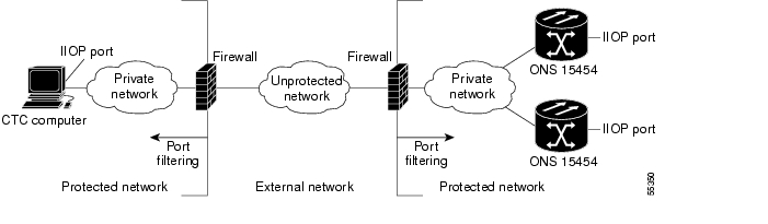
Figure 3-7 shows a CTC computer and ONS 15454 behind firewalls. For the computer to access the ONS 15454, you must provision the IIOP port on the CTC computer and on the ONS 15454.
Figure 3-7 CTC Computer and ONS 15454 Nodes Residing Behind Firewalls
Stop. You have completed this procedure.
DLP-G61 Provision the IIOP Listener Port on the ONS 15454
Note
Step 1
Step 2
•
•
•
Step 3
Step 4
Both ONS 15454 TCC2/TCC2P cards reboot, one at a time. The reboot takes approximately 15 minutes.
Step 5
DLP-G62 Provision the IIOP Listener Port on the CTC Computer
Purpose
This task selects the IIOP listener port for CTC and must be completed if the computer running CTC resides behind a firewall.
Tools/Equipment
IIOP listener port number from LAN or firewall administrator
Prerequisite Procedures
G22 Verify Common Card Installation
Required/As Needed
As needed
Onsite/Remote
Onsite or remote
Security Level
Provisioning or higher
Step 1
Step 2
Step 3
•
•
•
Step 4
Step 5
Step 6
Step 7
Step 8
NTP-G132 Provision OSI
Caution
Note
Step 1
Step 2
•
•
•
•
•
•
•
•
Stop. You have completed this procedure.
DLP-G283 Provision OSI Routing Mode
Purpose
This task provisions the OSI routing mode. Complete this task when the ONS 15454 is connected to networks with third party NEs that use the OSI protocol stack for DCN communication.
Tools/Equipment
None
Prerequisite Procedures
NTP-G15 Install the Common Control Cards, page 1-76
Required/As Needed
As needed
Onsite/Remote
Onsite
Security Level
Provisioning or higher
Caution
Caution
Caution
Note
Step 1
Step 2
•
Note
•
•
–
–
Step 3
•
•
Step 4
DLP-G284 Provision the TARP Operating Parameters
Step 1
Step 2
•
Note
•
Note
•
–
–
–
Note
•
Note
•
Note
•
Note
•
•
•
Note
•
•
•
•
•
•
Note
Step 3
Step 4
DLP-G285 Add a Static TID-to-NSAP Entry to the TARP Data Cache
Step 1
Step 2
Step 3
•
•
Step 4
Step 5
DLP-G287 Add a TARP Manual Adjacency Table Entry
Step 1
Step 2
Step 3
•
–
–
•
Step 4
Step 5
DLP-G288 Provision OSI Routers
Purpose
This task enables an OSI router and edits its primary manual area address.
Tools/Equipment
None
Prerequisite Procedures
G22 Verify Common Card Installation
Required/As Needed
As needed
Onsite/Remote
Onsite or remote
Security Level
Provisioning or higher
Note
Note
Note
Step 1
Step 2
Step 3
a.
b.
c.
d.
Step 4
DLP-G289 Provision Additional Manual Area Addresses
Purpose
This task provisions the OSI manual area addresses. One primary area and two additional manual areas can be created for each virtual router.
Tools/Equipment
None
Prerequisite Procedures
G22 Verify Common Card Installation
Required/As Needed
As needed
Onsite/Remote
Onsite or remote
Security Level
Provisioning or higher
Step 1
Step 2
Step 3
a.
b.
c.
d.
Step 4
DLP-G290 Enable the OSI Subnet on the LAN Interface
Purpose
This task enables the OSI subnetwork point of attachment on the LAN interface.
Tools/Equipment
None
Prerequisite Procedures
G22 Verify Common Card Installation
Required/As Needed
As needed
Onsite/Remote
Onsite or remote
Security Level
Provisioning or higher
Note
Note
Note
Step 1
Step 2
Step 3
•
•
•
•
•
Step 4
Step 5
DLP-G291 Create an IP-Over-CLNS Tunnel
Purpose
This task creates an IP-over-CLNS tunnel to allow ONS 15454 nodes to communicate across equipment and networks that use the OSI protocol stack.
Tools/Equipment
None
Prerequisite Procedures
G22 Verify Common Card Installation
Required/As Needed
As needed
Onsite/Remote
Onsite or remote
Security Level
Provisioning or higher
Caution
Step 1
Step 2
Step 3
•
–
–
The Cisco proprietary tunnel is slightly more efficient than the GRE tunnel because it does not add the GRE header to each IP packet. The two tunnel types are not compatible. Most Cisco routers support the Cisco IP tunnel, while only a few support both GRE and Cisco IP tunnels. You generally should create Cisco IP tunnels if you are tunneling between two Cisco routers or between a Cisco router and an ONS node.
Caution
•
•
•
•
Step 4
Step 5
Step 6
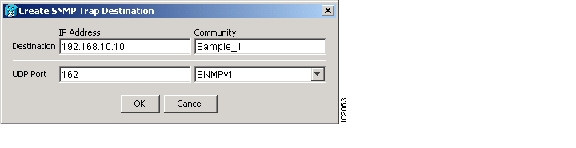
NTP-G28 Set Up SNMP
Step 1
Step 2
Step 3
Step 4
•
•
Note
•
•
Figure 3-8 Creating an SNMP Trap
Step 5
Step 6
Step 7
Step 8
Note
Note
For more information about the SNMP proxy feature, refer to the "SNMP" chapter in the Cisco ONS 15454 DWDM Reference Manual.
Step 9
Step 10
a.
b.
Note
Note
Step 11
Stop. You have completed this procedure.
NTP-G143 Import the Cisco MetroPlanner NE Update Configuration File
Caution
Note
Step 1
Step 2
a.
b.
•
•
c.
d.
Step 3
a.
b.
c.
Step 4
Step 5
Step 6
Note
Step 7
Step 8
a.
b.
Step 9
•
•
–
–
•
•
•
•
Note
•
Step 10
Table 3-2 NE Update Wizard Options
Node Layout
View the cards and slots on the left side of the page and verify that they are the same as the layout in the Cisco MetroPlanner Shelf Layout (see Table 3-1). If the cards and slots match, click Apply. If not, click Cancel. and contact your next level of support to verify that you have the correct node setup file. If the site has a multishelf configuration, click Next and repeat this step for each shelf at the site.
CTC preprovisions the slots. (This might take a few seconds.) The results appear in the Log window. Slots that are successfully provisioned display an "Applied" status. A "Slot not empty" status appears if slots cannot be provisioned because a card is physically installed or the slot is already provisioned. If this occurs, complete the following steps. Otherwise, continue with the next NE Update function.
1.
2.
3.
–
–
Note
Card Parameters
1.
2.
3.
Pluggable Port Modules
1.
2.
3.
Internal Patchcords
1.
2.
3.
Optical Sides
1.
2.
3.
ANS Parameters
1.
c.
Step 11
Note
Stop. You have completed this procedure.
DLP-G351 Delete a Card in CTC
Step 1
•
•
•
•
•
•
If any of these conditions exist, do not continue. You will not be able to delete the card until the card is removed from protection groups; circuits, DCC, and GCCs are deleted; a different timing source is provisioned, and the LMP link or channel is deleted.
•
•
•
•
•
•
Step 2
Note
Step 3
DLP-G353 Preprovision a Single Slot
Purpose
This task preprovisions a single ONS 15454 slot in CTC. Preprovisioning of all the slots in the shelf is normally performed when you complete the "G143 Import the Cisco MetroPlanner NE Update Configuration File" procedure. Use this task if you need to manually preprovision a single slot. All slot preprovisioning must be based upon the Cisco MetroPlanner shelf layout prepared for your site.
Tools/Equipment
Cisco MetroPlanner shelf layout table or JPG file.
Prerequisite Procedures
G139 Verify Cisco MetroPlanner Reports and Files
Required/As Needed
As needed
Onsite/Remote
Onsite or remote
Security Level
Provisioning or higher
Step 1
Step 2
Note
Step 3
Stop. You have completed this procedure.
NTP-G30 Install the DWDM Cards
Purpose
This procedure describes how to install the DWDM multiplexer, demultiplexer, wavelength selective switch, wavelength cross-connect, OADM, OSC, and optical amplifier cards.
Tools/Equipment
Cisco MetroPlanner shelf layout
The following cards, as required by your site plan:
•
•
The ONS 15454 NE defaults file if the node will use custom NE defaults
Prerequisite Procedures
NTP-G15 Install the Common Control Cards, page 1-76
NTP-G14 Install DWDM Equipment, page 1-68
G139 Verify Cisco MetroPlanner Reports and Files
G143 Import the Cisco MetroPlanner NE Update Configuration File
Required/As Needed
As needed
Onsite/Remote
Onsite
Security Level
Provisioning or higher
Warning
Warning
Warning
Warning
Warning
Caution
Note
Note
Note
Step 1
Caution
Step 2
•
•
Step 3
Step 4
Step 5
Step 6
Step 7
Note
After installing the card, the following LED activity will occur:
•
•
•
Step 8
•
•
•
•
If any of conditions are present, remove the card and repeat Steps 4 to 7 . If the card does not boot up properly the second time, it might be defective. Contact your next level of support.
Step 9
Step 10
•
•
Stop. You have completed this procedure.
DLP-G348 Use the Cisco MetroPlanner Shelf Layout Report
Step 1
Figure 3-9 Cisco MetroPlanner Shelf Layout Report Displayed in Cisco MetroPlanner
Step 2
•
•
–
–
–
•
–
–
•
•
Step 3
NTP-G31 Install the DWDM Dispersion Compensating Units
Purpose
This procedure describes how to install the DCUs for DWDM shelves.
Tools/Equipment
DCUs
Prerequisite Procedures
NTP-G15 Install the Common Control Cards, page 1-76
NTP-G14 Install DWDM Equipment, page 1-68
Required/As Needed
As needed
Onsite/Remote
Onsite
Security Level
Provisioning or higher
Warning
Warning
Caution
Note
Step 1
Step 2
Step 3
Note
Note
Stop. You have completed this procedure.
NTP-G179 Install the TXP, MXP, GE_XP, 10GE_XP, and ADM-10G Cards
Purpose
This procedure describes how to install the ONS 15454 TXP, MXP, GE_XP, 10GE_XP, and ADM-10G cards.
Tools/Equipment
TXP_MR_10G, TXP_MR_10E, TXP_MR_10E_C, TXP_MR_10E_L, TXP_MR_2.5G, TXPP_MR_2.5G, MXP_2.5G_10G, MXPP_2.5G_10G, MXP_2.5G_10E, MXP_2.5G_10E_C, MXP_2.5G_10E_L, MXP_MR_2.5G, MXP_MR_10DME_C, MXP_MR_10DME_L, 10GE_XP, GE_XP, or ADM-10G cards (as applicable)
Prerequisite Procedures
NTP-G15 Install the Common Control Cards, page 1-76
NTP-G14 Install DWDM Equipment, page 1-68
Required/As Needed
As needed
Onsite/Remote
Onsite
Security Level
None
Warning
Warning
Warning
Warning
Caution
Note
Note
Note
Step 1
Step 2
Step 3
Step 4
Step 5
Note
Note
After you install the card, the FAIL, ACT, and SF LEDs will go through a sequence of activities. They will turn on, turn off, and blink at different points. After approximately 2 to 3 minutes, the ACT or ACT/STBY LED turns on. The SF LED might persist until all card ports connect to their far-end counterparts and a signal is present.
Note
Step 6
•
•
•
•
If any of these conditions are present, remove the card and repeat Steps 3 to 5 . If the card does not boot up properly the second time, contact your next level of support.
Step 7
•
•
Note
Note
Step 8
Note
Note
Stop. You have completed this procedure.
DLP-G63 Install an SFP or XFP
Purpose
This task installs SFPs and XFPs into TXP, MXP, GE_XP, 10GE_XP and ADM-10G cards. SFPs and XFPs provide a fiber interface to the card.
Tools/Equipment
None
Prerequisite Procedures
G179 Install the TXP, MXP, GE_XP, 10GE_XP, and ADM-10G Cards
Required/As Needed
As needed
Onsite/Remote
Onsite
Security Level
Provisioning or higher
Warning
Note
Note
Note
Step 1
Step 2
•
•
•
Note
Step 3
Step 4
DLP-G273 Preprovision an SFP or XFP Slot
Note
Step 1
Step 2
Step 3
Step 4
•
•
Step 5
Step 6
Step 7
Step 8
Step 9
DLP-G64 Remove an SFP or XFP
Purpose
This task removes SFPs and XFPs from TXP, MXP, GE_XP, 10GE_XP, and ADM-10G cards.
Tools/Equipment
None
Prerequisite Procedures
G179 Install the TXP, MXP, GE_XP, 10GE_XP, and ADM-10G Cards
Required/As Needed
As needed
Onsite/Remote
Onsite
Security Level
Provisioning or higher
Note
Step 1
Step 2
•
•
•
Step 3
Step 4
NTP-G123 Install the Filler Cards
Purpose
This procedure explains how to install the filler cards (blank faceplates) in any unused traffic or AIC-I card slots (Slots 1 through 6, 9, and 11 through 17). The filler card aids in maintaining proper air flow and electro-magnetic interference (EMI) requirements and is detected by CTC in Software Release 6.0 and later.
Tools/Equipment
Filler cards (Cisco P/N 15454-FILLER)
Prerequisite Procedures
G31 Install the DWDM Dispersion Compensating Units
G179 Install the TXP, MXP, GE_XP, 10GE_XP, and ADM-10G Cards
Required/As Needed
As needed
Onsite/Remote
Onsite
Security Level
None
Warning
Caution
Step 1
Step 2
Step 3
Step 4
Stop. You have completed this procedure.
NTP-G34 Install Fiber-Optic Cables on DWDM Cards and DCUs
Purpose
This procedure attaches fiber-optic cables on the DWDM cards and DCUs.
Tools/Equipment
Fiber-optic cables
Cisco MetroPlanner Internal Connections Report
Prerequisite Procedures
G31 Install the DWDM Dispersion Compensating Units (as applicable)
Required/As Needed
As needed
Onsite/Remote
Onsite
Security Level
None
Warning
Note
Note
Note
Step 1
Step 2
a.
b.
Step 3
Step 4
Step 5
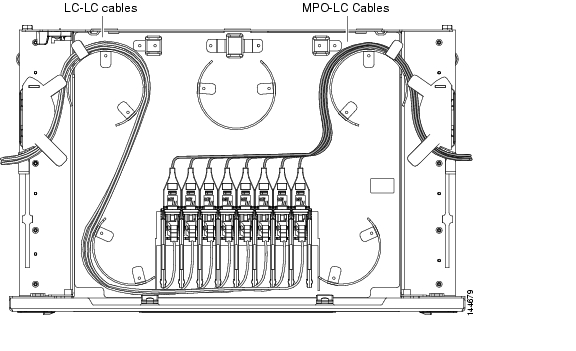
Step 6
Figure 3-10 Managing Cables on the Front Panel
Step 7
Step 8
Step 9
Step 10
Figure 3-11 Fiber-Storage Tray
Caution
Step 11
Step 12
Note
Step 13
Step 14
Stop. You have completed this procedure.
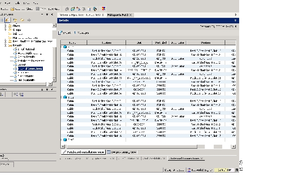
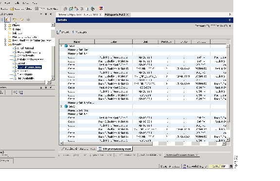
DLP-G349 Use the Cisco MetroPlanner Internal Connections Report
Step 1
The table identifies the patchcords that you must cable by their endpoints. Position 1 identifies the fiber start point; Position 2 indicates the fiber endpoint. The patchcord endpoints are identified by site, slot, and port. Information provided by the Internal Connections report includes:
•
•
•
•
•
•
•
Note
•
•
•
•
•
•
Caution
Figure 3-12 Cisco MetroPlanner Internal Connections Report—Patchcord Installation View
Figure 3-13 Cisco MetroPlanner Internal Connections Report—Software Provisioning View
Step 2
NTP-G140 Install Fiber-Optic Cables Between Terminal, Hub, or ROADM Nodes
Purpose
This procedure routes fiber-optic cables from the DWDM optical cards in a terminal, hub, or ROADM node to the patch panel, and from the patch panel to TXP, MXP, GE_XP, 10GE_XP, or ADM-10G cards.
Tools/Equipment
See Step 1 for a list of equipment specific to each node type.
All node types require fiber-optic cables, terminated with a single LC-type connector on each end.
Cisco MetroPlanner Internal Connections Report
Prerequisite Procedures
DLP-G28 Install the Fiber Patch-Panel Tray, page 1-70
DLP-G29 Install the Fiber-Storage Tray, page 1-70
G34 Install Fiber-Optic Cables on DWDM Cards and DCUs
Required/As Needed
As needed
Onsite/Remote
Onsite
Security Level
None
Step 1
The following node types require the listed equipment. The cards and patch panels should already be installed before you begin this procedure.
•
•
•
•
Note
Step 2
Step 3
Note
Step 4
•
–
–
•
–
•
–
Step 5
Caution
Stop. You have completed this procedure.
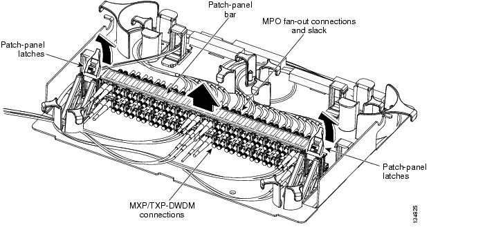
DLP-G315 Install Fiber-Optic Cables From the 32WSS/32DMX and 32MUX-O/32DMX-O Cards to the Standard Patch-Panel Tray
Note
Step 1
Step 2
Figure 3-14 Using the Patch-Panel Latches to Slide the Patch Panel Away from the Tray
Step 3
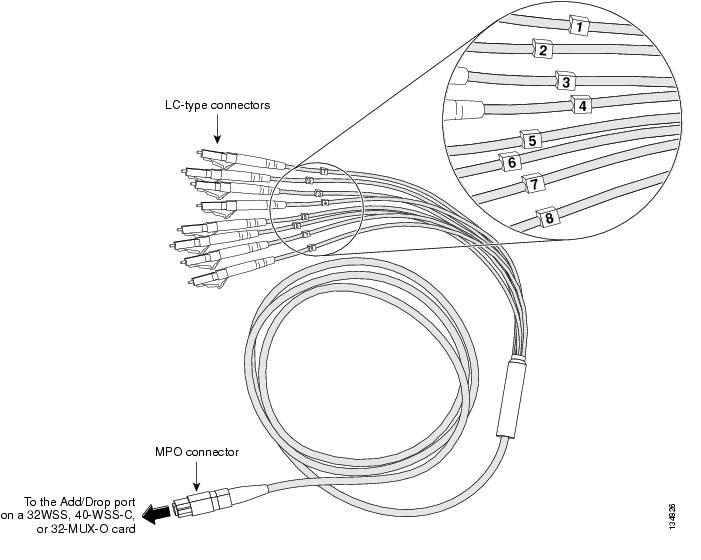
Figure 3-15 MPO Cable
.
Step 4
Caution
Step 5
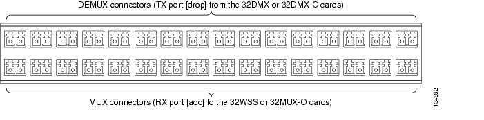
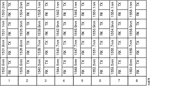
Figure 3-16 shows the patch-panel connectors from the rear of the patch-panel tray. Figure 3-17 shows the assigned wavelengths for each port on the patch panel, as indicated at the top of the patch-panel bar. The numbers on the patch-panel bar correspond to a wavelength on the ITU grid.
Figure 3-16 Rear View of the Patch Panel
.
Figure 3-17 Top View of the Patch-Panel Bar
Step 6
Step 7
Step 8
Caution
Step 9
Step 10
Step 11
Step 12
DLP-G316 Install Fiber-Optic Cables from TXP, MXP, GE_XP, 10GE_XP, or ADM-10G Cards to the Standard Patch-Panel Tray
Step 1
Step 2
Caution
Step 3
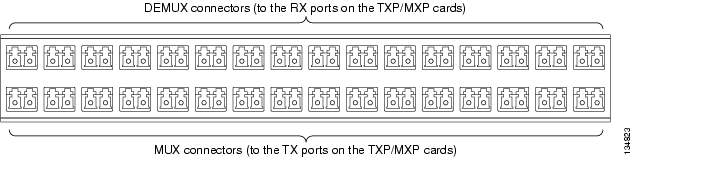
Figure 3-18 shows the patch-panel connectors from the front of the patch-panel tray.
Figure 3-18 Front View of the Patch Panel
.
Step 4
Step 5
Step 6
Step 7
DLP-G356 Install Fiber-Optic Cables from the 32WSS/32DMX and 32MUX-O/32DMX-O Cards to the Deep Patch-Panel Tray
Note
Step 1
Step 2
Step 3
Figure 3-19 Deep Patch-Panel Tray
Step 4
Caution
Step 5
Step 6
Step 7
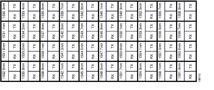
Figure 3-20 shows the deep patch-panel ports and corresponding wavelengths.
Figure 3-20 Deep Patch-Panel Port Wavelengths
Step 8
Step 9
Step 10
Step 11
Caution
Step 12
Step 13
DLP-G427 Reroute Fiber-Optic Cables in the 40-Channel Patch-Panel Tray
Step 1
Figure 3-21 and Figure 3-22 show the 40-channel patch-panel tray.
Figure 3-21 40-Channel Patch-Panel Tray, Side View
Figure 3-22 40-Channel Patch-Panel Tray, Top View
Step 2
Step 3
Step 4
Step 5
Step 6
Step 7
Step 8
Step 9
DLP-G428 Install Fiber-Optic Cables from the 40-WSS-C and 40-DMX-C Cards in an Expanded ROADM, Terminal, or Hub Node to the 40-Channel Patch-Panel Tray
Purpose
This task describes how to route fiber-optic cables from 40-WSS-C and 40-DMX-C cards in an expanded ROADM, terminal, or hub node to the 40-channel (80-port) patch-panel tray (15454-PP-80).
Tools/Equipment
The following node types require the following equipment. The cards and patch panels should already be installed before you begin this procedure.
Expanded terminal nodes:
•
•
Plus one 40-channel patch-panel tray, preinstalled with MPO cables (each MPO cable is terminated on one end with one MPO connector and on the other end with eight LC-type connectors)
Expanded hub or ROADM nodes:
•
•
Plus two 40-channel patch-panel trays, preinstalled with MPO cables (each MPO cable is terminated on one end with one MPO connector and on the other end with eight LC-type connectors)
Prerequisite Procedures
G34 Install Fiber-Optic Cables on DWDM Cards and DCUs
G427 Reroute Fiber-Optic Cables in the 40-Channel Patch-Panel Tray
Required/As Needed
As needed
Onsite/Remote
Onsite
Security Level
None
Note
Step 1
Note
Step 2
Step 3
Step 4
Step 5
Step 6
Step 7
Caution
Figure 3-23 shows the 40-channel patch-panel ports and corresponding wavelengths.
Figure 3-23 40-Channel (15454-PP-80) Patch-Panel Port Wavelengths
Step 8
Step 9
Step 10
Step 11
Step 12
Caution
Step 13
Step 14
DLP-G357 Install Fiber-Optic Cables from the TXP, MXP, GE_XP, 10GE_XP, or ADM-10G Cards to the Deep Patch-Panel Tray or 40-Channel Patch-Panel Tray
Step 1
Step 2
Caution
Step 3
Step 4
Step 5
Step 6
Step 7
Step 8
NTP-G185 Install Fiber-Optic Cables between Mesh Nodes
Purpose
This procedure describes how to install fiber-optic cables to create mesh nodes. You must route fiber-optic cables from 40-MUX-C and 40-DMX-C cards in a mesh node to the 40-channel (80-port) patch-panel tray (15454-PP-80), and from the 40-WXC-C cards in a mesh node to one of the mesh patch-panel trays (four-degree or eight-degree).
Tools/Equipment
Mesh nodes require the following equipment. The cards and patch panels should already be installed before you begin this procedure.
One 40-MUX-C card per side of the mesh node (up to 8 sides per node)One 40-DMX-C card per side of the mesh node (up to 8 sides per node)One 40-channel patch-panel tray per side of the mesh node (up to 8 sides per node)
One 40-WXC-C card per side (up to 8 sides per node)
One MPO-MPO fiber-optic cable per side (up to 8 sides per node)
One LC-LC fiber-optic cable per side (up to 8 sides per node)
One four-degree (PP-MESH-4) or eight-degree (PP-MESH-8) mesh patch-panel tray, depending on the type of mesh node you want to install
Prerequisite Procedures
G34 Install Fiber-Optic Cables on DWDM Cards and DCUs
G427 Reroute Fiber-Optic Cables in the 40-Channel Patch-Panel Tray
Required/As Needed
As needed
Onsite/Remote
Onsite
Security Level
None
Step 1
•
•
Step 2
Step 3
Step 4
•
•
Caution
Stop. You have completed this procedure.
DLP-G430 Install Fiber-Optic Cables from the 40-MUX-C and 40-DMX-C Cards in a Mesh Node to the 40-Channel Patch-Panel Tray
Purpose
This task describes how to route fiber-optic cables from 40-MUX-C and 40-DMX-C cards in mesh node to the 40-channel (80-port) patch-panel tray (15454-PP-80). In a mesh node, one 40-channel patch panel tray is required for each direction. The Side A 40-MUX-C and 40-DMX-C cards will connect to the Side A 40-channel patch panel. The Side B 40-MUX-C and 40-DMX-C cards will connect to the Side B 40-channel patch panel, and so forth, up to a maximum of an eight-degree mesh node (Sides A through H).
Tools/Equipment
The cards and patch panels should already be installed before you begin this procedure.
One 40-MUX-C card per side of the mesh node
One 40-DMX-C card per side of the mesh node
One 40-channel patch-panel trays per side of the mesh node, preinstalled with MPO cables (each MPO cable is terminated on one end with one MPO connector and on the other end with eight LC-type connectors)
Prerequisite Procedures
G34 Install Fiber-Optic Cables on DWDM Cards and DCUs
G427 Reroute Fiber-Optic Cables in the 40-Channel Patch-Panel Tray
Required/As Needed
As needed
Onsite/Remote
Onsite
Security Level
None
Step 1
Note
Step 2
Step 3
Step 4
Step 5
Step 6
Step 7
Step 8
Step 9
Step 10
Step 11
Step 12
Caution
Step 13
Step 14
DLP-G431 Install Fiber-Optic Cables from the 40-WXC-C Cards in a Mesh Node to a Mesh Patch-Panel Tray
Purpose
This task connects fiber-optic cables from the 40-WXC-C cards in a mesh node to the 4-degree or 8-degree mesh patch panel. The four-degree patch panel allows up to 4 sides to be used per node, while the eight-degree patch panel allows up to 8 sides to be used per node.
Tools/Equipment
The cards and patch panel trays should already be installed before you begin this procedure.
One 40-WXC-C card per side (up to 8 sides per node)
One MPO-MPO fiber-optic cable per side
One LC-LC fiber-optic cable per side
One four-degree or eight-degree mesh patch-panel tray
Cisco MetroPlanner Internal Connections Report
Prerequisite Procedures
DLP-G28 Install the Fiber Patch-Panel Tray, page 1-70
DLP-G29 Install the Fiber-Storage Tray, page 1-70
G34 Install Fiber-Optic Cables on DWDM Cards and DCUs
Required/As Needed
As needed
Onsite/Remote
Onsite
Security Level
None
Step 1
Step 2
Step 3
Step 4
Step 5
Step 6
Step 7
Step 8
Caution
Stop. You have completed this procedure.
NTP-G191 Install Fiber-Optic Cables on Passthrough ROADM Nodes
Purpose
This procedure routes fiber-optic cables from a 32WSS card in a ROADM node in one shelf to the corresponding 32WSS card in a ROADM node in another shelf. The purpose of this routing is to connect East and West intershelf ROADMs in a passthrough configuration.
Tools/Equipment
Each ROADM node requires the listed equipment. The cards and fiber-storage trays should already be installed before you begin this procedure.
•
•
•
•
Prerequisite Procedures
DLP-G29 Install the Fiber-Storage Tray, page 1-70
Required/As Needed
As needed
Onsite/Remote
Onsite
Security Level
None
Step 1
Step 2
Step 3
Step 4
Step 5
Figure 3-24 Managing Cables on the Front Panel
Step 6
Step 7
Step 8
Step 9
Step 10
Figure 3-25 Fiber-Storage Tray
Caution
Step 11
Step 12
Step 13
Step 14
Step 15
Step 16
Step 17
Stop. You have completed this procedure.
NTP-G141 Install Fiber-Optic Cables for Y-Cable Protection Modules
Purpose
This procedure installs and routes fiber-optic cables from the client signal to the Y-cable protection module (single mode or multimode), and from the Y-cable module to the transponder node. Using one Y-cable protection module, you can protect one client signal with two TXP, MXP, GE_XP, or 10GE_XP cards, and two client signals with four TXP, MXP, GE_XP, or 10GE_XP cards. You can use Y-cable protection modules that you have installed in a FleyLayer shelf, or Y-cable modules installed in a Y-cable module tray.
Tools/Equipment
Fiber-optic cables
Cisco MetroPlanner Internal Connections Report
Prerequisite Procedures
DLP-G32 Install the Y-Cable Protection Modules in the FlexLayer Shelf, page 1-75
DLP-G377 Install the Y-Cable Protection Modules in the Y-Cable Module Tray, page 1-75
Required/As Needed
As needed
Onsite/Remote
Onsite
Security Level
None
Note
Note
Step 1
Step 2
Stop. You have completed this procedure.
DLP-G375 Install Fiber-Optic Cables on the Y-Cable Modules in the FlexLayer Shelf
Purpose
This task installs fiber-optic cables from the TXP, MXP, GE_XP, or 10GE_XP cards to the Y-cable modules installed in the FlexLayer shelves, and from the Y-cable modules to the client devices.
Tools/Equipment
Fiber-optic cables
Cisco MetroPlanner Internal Connections Report
Prerequisite Procedures
DLP-G32 Install the Y-Cable Protection Modules in the FlexLayer Shelf, page 1-75
G179 Install the TXP, MXP, GE_XP, 10GE_XP, and ADM-10G Cards
Required/As Needed
As needed
Onsite/Remote
Onsite
Security Level
None
Step 1
If you want to protect one client signal, connect the fiber-optic cables according to either Table 3-4 or Table 3-5. To protect two client signals using a single Y-cable module, connect the cables according to both Table 3-4 and Table 3-5.
Step 2
Caution
Step 3
Step 4
Step 5
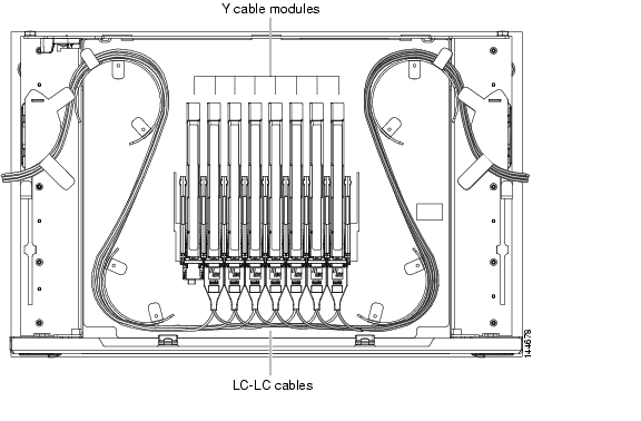
DLP-G376 Install Fiber-Optic Cables on the Y-Cable Modules in the Y-Cable Module Tray
Purpose
This task installs fiber-optic cables from the TXP, MXP, GE_XP, or 10GE_XP cards to the Y-cable modules installed in the Y-cable module tray, and from the Y-cable modules to the client devices.
Tools/Equipment
Fiber-optic cables (4-meter [13.12-foot]), single-mode or multimode as appropriate
Cisco MetroPlanner Internal Connections Report
Prerequisite Procedures
DLP-G32 Install the Y-Cable Protection Modules in the FlexLayer Shelf, page 1-75
G179 Install the TXP, MXP, GE_XP, 10GE_XP, and ADM-10G Cards
Required/As Needed
As needed
Onsite/Remote
Onsite
Security Level
None
Step 1
Step 2
Step 3
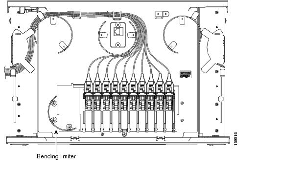
Figure 3-26 Y-Cable Protection Port Label
Note
Note
As needed, route slack fiber-optic cable around the round cable retainers in theY-cable module tray as you install cables between the Y-cable module and the TXP, MXP, GE_XP, or 10GE_XP card ( Figure 3-27).
Figure 3-27 Y-Cable Protection Module Tray
Caution
Step 4
Step 5
Step 6
Step 7
Step 8
NTP-G152 Create and Verify Internal Patchcords
Purpose
This procedure creates the default internal patchcords, verifies the installed cards, and calculates the connections that should be provisioned for them.
Tools/Equipment
Cisco MetroPlanner shelf layout
Cisco MetroPlanner Internal Connections Report
Prerequisite Procedures
G22 Verify Common Card Installation
Required/As Needed
Required
Onsite/Remote
Onsite or remote
Security Level
Superuser only
Step 1
Step 2
Step 3
CTC verifies that the cards installed in the ONS 15454 shelf are compatible and will operate together as a valid DWDM node configuration. Furthermore, based on the cards installed or preprovisioned, CTC calculates the intra-shelf patchcords that are expected to be installed.
Note
Note
Step 4
Step 5
Step 6
Note
Stop. You have completed this procedure.
DLP-G354 Create an Internal Patchcord Manually
Step 1
Step 2
Step 3
•
•
Note
The remaining fields on the page depend on the patchcord type selected.
•
•
Note
Step 4
Step 5
•
•
•
Step 6
Step 7
•
•
•
Step 8
Step 9
Step 10
Step 11
Step 12
Step 13
DLP-G355 Delete an Internal Patchcord
Purpose
This task deletes an internal patchcord.
Tools/Equipment
None
Prerequisite Procedures
Required/As Needed
As needed
Onsite/Remote
Onsite or remote
Security Level
Superuser only
Step 1
Step 2
Step 3
Step 4
NTP-G38 Provision OSC Terminations
Purpose
This procedure provisions the OSC terminations. The OSC provides a bidirectional channel that connects all nodes within a DWDM ring. The OSC carries a supervisory data channel and synchronizes clocking at network nodes. The OSC also carries a user data channel.
Tools/Equipment
None
Prerequisite Procedures
G143 Import the Cisco MetroPlanner NE Update Configuration File
Required/As Needed
Required
Onsite/Remote
Onsite or remote
Security Level
Superuser only
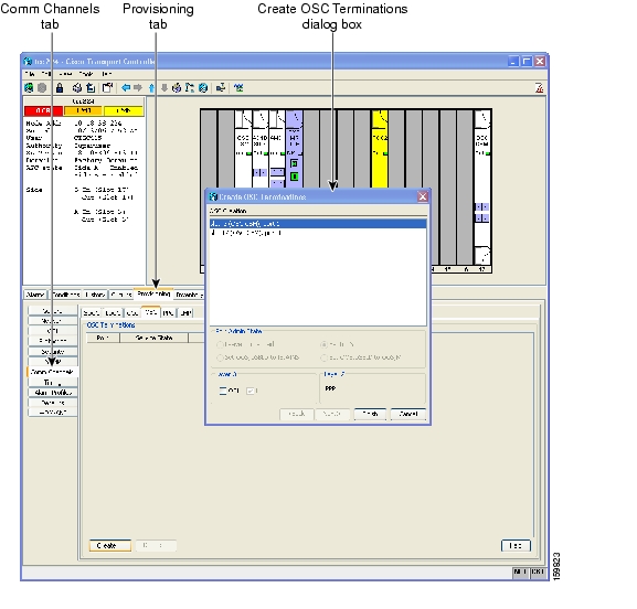
Step 1
Step 2
Step 3
Figure 3-28 OSC Terminations Area
Step 4
Note
Step 5
•
•
If you checked OSI, complete the following steps. If not, continue with Step 6.
a.
b.
•
•
•
•
•
Step 6
•
•
•
Note
Stop. You have completed this procedure.
NTP-G37 Run Automatic Node Setup
Purpose
This procedure runs the Launch ANS function. Launch ANS applies the ANS parameters (calculated in the "G143 Import the Cisco MetroPlanner NE Update Configuration File" procedure or the "G169 Calculate ANS Installation Values for Installation Without Cisco MetroPlanner" procedure) to the node and to the ports for cards installed in the node. The applied ANS parameters include span loss values, threshold values, power references, and others. Launch ANS also sets the VOA references based on the calculated power references.
Tools/Equipment
The Cisco MetroPlanner Installation Parameters file
Prerequisite Procedures
G139 Verify Cisco MetroPlanner Reports and Files
G152 Create and Verify Internal Patchcords
G143 Import the Cisco MetroPlanner NE Update Configuration File
Required/As Needed
Required
Onsite/Remote
Onsite or remote
Security Level
Superuser only
Note
Step 1
Step 2
Step 3
Step 4
Step 5
Step 6
Step 7
Step 8
Step 9
Step 10
Step 11
•
•
•
If one of the following statuses is shown, complete the provided instructions:
•
•
Note
Stop. You have completed this procedure.
NTP-G39 Verify OSCM and OSC-CSM Transmit Power
Note
Step 1
Step 2
a.
b.
c.
d.
Step 3
a.
b.
c.
d.
Step 4
•
•
Step 5
a.
b.
c.
d.
Step 6
a.
b.
c.
d.
Stop. You have completed this procedure.
DLP-G313 Verify OSC-CSM Transmit Power
Note
Step 1
Step 2
Step 3
Step 4
Step 5
For OSC-CSM cards installed on Side B:
a.
b.
c.
d.
For OSC-CSM cards installed on Side A:
a.
b.
c.
d.
Step 6
a.
b.
c.
d.
e.
Step 7
a.
b.
c.
d.
e.
f.
g.
h.
Step 8
a.
b.
c.
d.
e.
f.
g.
Step 9
DLP-G314 Verify OSCM Transmit Power
Note
Step 1
Step 2
Step 3
Step 4
Step 5
For OSCM cards installed on the Side B:
a.
b.
c.
d.
For OSCM cards installed on Side A:
a.
b.
c.
d.
Step 6
a.
b.
c.
•
•
•
d.
Step 7
NTP-G163 Upgrade Nodes in Single-Shelf Mode to Multishelf Mode
Purpose
This procedure upgrades nodes in single-shelf mode to multishelf mode.
Tools/Equipment
The node you plan to use as the node controller must be equipped with optical units and cannot have a cross-connect card installed. Any nodes that you plan to add to the multishelf configuration as subtending shelves can be equipped with transponder and muxponder units. For more information on multishelf configurations, see the "Node Reference" chapter in the Cisco ONS 15454 DWDM Reference Manual.
Prerequisite Procedures
G22 Verify Common Card Installation
One of the following procedures:
•
•
Required/As Needed
As needed
Onsite/Remote
Onsite
Security Level
Superuser only
Caution
Step 1
Step 2
Step 3
a.
b.
c.
•
•
d.
e.
f.
Note
Step 4
a.
b.
c.
d.
Caution
•
•
•
e.
f.
g.
h.
i.
j.
k.
l.
m.
n.
o.
Note
Stop. You have completed this procedure.
![]()
![]()
![]()
![]()
![]()
![]()
![]()
![]()
Posted: Mon Oct 29 01:40:28 PDT 2007
All contents are Copyright © 1992--2007 Cisco Systems, Inc. All rights reserved.
Important Notices and Privacy Statement.