cc/td/doc/product/ong/15400/r80docs
hometocprevnextglossaryfeedbacksearchhelp
PDF

Table Of Contents

Installation Without Cisco MetroPlanner

B.1  Overview

B.2  Installation Without Cisco MetroPlanner Requirements

B.3  Turn Up a Node Using Installation Without Cisco MetroPlanner

B.3.1  Node Turn up Phase 1

B.3.2  Node Turn up Phase 2

NTP-G169 Calculate ANS Installation Values for Installation Without Cisco MetroPlanner


Installation Without Cisco MetroPlanner


Installation without Cisco MetroPlanner allows you to provision ONS 15454 automatic node setup (ANS) parameters without the Cisco MetroPlanner NE Update file. Instead, Cisco Transport Controller (CTC) provisions the ANS parameters using the data values that are calculated from the far-end nodes. However, because of the requirements and complexity of the installation-without-Cisco-MetroPlanner sequence, Cisco recommends that you do not use installation without Cisco MetroPlanner unless it is absolutely required.


Note The installation-without-Cisco-MetroPlanner feature enables you to turn up network nodes without the Cisco MetroPlanner NE Update file. However, you must use Cisco MetroPlanner to create the network design to ensure an implementation using the installation-without-Cisco-MetroPlanner is feasible.


Note Unless otherwise specified, "ONS 15454" refers to both ANSI and ETSI shelf assemblies.


Caution This feature requires planning and preparation. Do not begin until you have a full understanding of the requirements and turn-up sequence.

B.1  Overview

During normal ONS 15454 turn up, a Cisco MetroPlanner NE Update file is imported into each ONS 15454 node and used by CTC to provision the ONS 15454 ANS parameters. (See the "NTP-G143 Import the Cisco MetroPlanner NE Update Configuration File" procedure on page 3-43.) The NE Update file ensures that all node parameters are set to levels that meet the specific requirements of your network. Installation without Cisco MetroPlanner provides a method for calculating the required installation values without the NE Update file. ANS uses the calculated values to provision the node parameters.

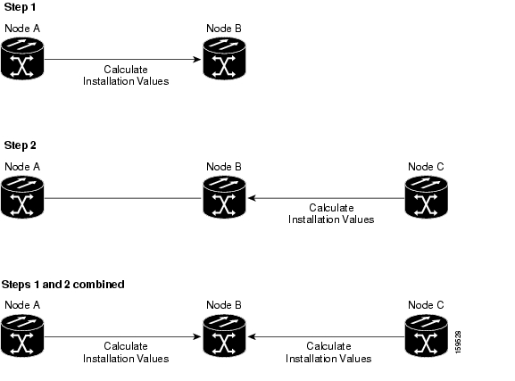
Installation without Cisco MetroPlanner requires physical and optical service channel (OSC) connections to far-end nodes. For example, in Figure B-1, Node B is the node that will be provisioned using installation without Cisco MetroPlanner. If only one far-end node is connected (Node A in this example), installation without Cisco MetroPlanner retrieves values to provision the side that is connected to Node A (Step 1). If Node C is later connected to Node B, installation without Cisco MetroPlanner must be run again to provision the side connected to Node C (Step 2). Alternatively, installation without Cisco MetroPlanner can be run after both far-end nodes are connected, meaning the installation values are retrieved for both Node A and Node C at one time (Steps 1 and 2 combined).

The same sequence must be repeated at each network node. After Node B is provisioned, you move to Node C. If it is connected to Node B only, installation must be run twice, once for the Node B side. If Node D is connected later, installation without Cisco MetroPlanner must be run again. If Node C is connected to Nodes B and D, installation without Cisco MetroPlanner can be run once to provision Node C.

Figure B-1 Installation Without Cisco MetroPlanner Provisioning

B.2  Installation Without Cisco MetroPlanner Requirements

The following requirements must be met before you can use the installation without Cisco MetroPlanner feature:

The network design must be prepared using Cisco MetroPlanner. Choose the installation-without-MetroPlanner option during network design. Cisco MetroPlanner will determine whether an installation without Cisco MetroPlanner is possible for your network (that is, whether the ANS parameters can be provisioned without the Cisco MetroPlanner NE Update file). If so, Cisco MetroPlanner designs the network assuming that you will use installation without Cisco MetroPlanner to turn up the network nodes.

OPT-PRE amplifier cards are required. If you choose the installation-without-MetroPlanner option in the Cisco MetroPlanner design, it will include OPT-PRE cards in all the network nodes.

Installation without Cisco MetroPlanner is available only for networks that are designed for a flat optical power spectrum (tilt = 0) transmitted over the optical fiber links.

Cross-connect (XC) termination meshed nodes are not supported.

Installation without Cisco MetroPlanner is not available over C+L (networks that have both C-band and L-band channels) or 50 Ghz networks.

Installation without Cisco MetroPlanner is not available on links using data communications network (DCN) extension. OSC connectivity is required.

B.3  Turn Up a Node Using Installation Without Cisco MetroPlanner

The node turn-up sequence using the installation-without-Cisco-MetroPlanner function is similar to the sequence using the Cisco MetroPlanner NE Update file with two key differences:

You do not perform the "NTP-G143 Import the Cisco MetroPlanner NE Update Configuration File" procedure on page 3-43. Instead, you use the "G169 Calculate ANS Installation Values for Installation Without Cisco MetroPlanner" procedure to calculate the values required to provision the node's parameters.

Because all network nodes must be turned up to the same point before the far-end node parameters are retrieved, node turn-up procedures are performed in two phases. Complete Phase 1 at all network nodes before completing Phase 2. Procedures in each phase are listed in the following sections.


Note For standard node turn-up using Cisco MetroPlanner see Chapter 3, "Turn Up a Node."


B.3.1  Node Turn up Phase 1

This section lists the non-trouble procedures (NTPs) needed to turn up a DWDM node using the installation-without-Cisco-MetroPlanner function. These procedures, and their accompanying tasks, must be completed at every network node before Phase 2 can begin.

1. NTP-G139 Verify Cisco MetroPlanner Reports and Files, page 3-3—Complete this procedure first.

2. NTP-G22 Verify Common Card Installation, page 3-5—Complete this procedure next.

3. NTP-G144 Provision a Multishelf Node, page 3-6—Complete this procedure as needed.

4. NTP-G23 Create Users and Assign Security, page 3-7—Complete this procedure to create CTC users and assign their security levels.

5. NTP-G24 Set Up Name, Date, Time, and Contact Information, page 3-10—Continue with this procedure to set the node name, date, time, location, and contact information.

6. NTP-G25 Set Battery Power Monitor Thresholds, page 3-12—Continue with this procedure to set the node battery power thresholds.

7. NTP-G26 Set Up CTC Network Access, page 3-13—Continue with this procedure to provision the IP address, default router, subnet mask, and other network configuration settings.

8. NTP-G27 Set Up the ONS 15454 for Firewall Access, page 3-27—Continue with this procedure if the ONS 15454 will be accessed behind firewalls.

9. NTP-G132 Provision OSI, page 3-31—Continue with this procedure if the ONS 15454 will be installed in networks with third-party, Open Systems Interconnection (OSI)-based network elements (NEs).

10. NTP-G28 Set Up SNMP, page 3-41—Complete this procedure if Simple Network Management Protocol (SNMP) will be used for network monitoring.

11. NTP-G30 Install the DWDM Cards, page 3-51—Complete this procedure to install the DWDM cards, including the OSCM, OSC-CSM, 32WSS, 32WSS-L, 40-WSS-C, 40-WXC-C, OPT-BST, OPT-BST-E, OPT-BST-L, OPT-AMP-L, OPT-AMP-17-C, OPT-PRE, 32MUX-O, 40-MUX-C, 32DMX-O, 32DMX, 32DMX-L, 40-DMX-C, 4MD-xx.x, AD-1C-xx.x, AD-2C-xx.x, AD-4C-xx.x, AD-1B-xx.x, AD-4B-xx.x, and MMU.

12. NTP-G31 Install the DWDM Dispersion Compensating Units, page 3-55—Complete this procedure, as needed, to install a dispersion compensating unit (DCU).

13. NTP-G179 Install the TXP, MXP, GE_XP, 10GE_XP, and ADM-10G Cards, page 3-56—Complete this procedure, as needed, to install transponder (TXP), muxponder (MXP), GE_XP, 10GE_XP, and ADM-10G cards.

14. NTP-G123 Install the Filler Cards, page 3-62—Complete this procedure, as needed, to install ONS 15454 filler cards.

15. NTP-G34 Install Fiber-Optic Cables on DWDM Cards and DCUs, page 3-63—Complete this procedure, as needed, to install the fiber-optic cables on the DWDM cards.

16. NTP-G140 Install Fiber-Optic Cables Between Terminal, Hub, or ROADM Nodes, page 3-68—Complete this procedure, as needed, to connect cards in a terminal, hub, or reconfigurable optical add/drop multiplexing (ROADM) node through the patch panel.

17. NTP-G141 Install Fiber-Optic Cables for Y-Cable Protection Modules, page 3-89—Complete this procedure, as needed, to connect fiber-optic cables to Y-cable modules from client TXP, MXP, GE_XP, 10GE_XP, and ITU cards.

18. NTP-G152 Create and Verify Internal Patchcords, page 3-94—Complete this procedure to calculate the DWDM cable connections.

19. NTP-G38 Provision OSC Terminations, page 3-98—Complete this procedure next.

Complete these procedures at each node in the network before you proceed to Phase 2 procedures.

B.3.2  Node Turn up Phase 2

Complete these procedures at each network node after the Phase 1 procedures are complete.

1. G169 Calculate ANS Installation Values for Installation Without Cisco MetroPlanner—Complete this procedure first.

2. NTP-G37 Run Automatic Node Setup, page 3-101—Complete this procedure next.

3. NTP-G39 Verify OSCM and OSC-CSM Transmit Power, page 3-102—Complete this procedure next.

4. NTP-G163 Upgrade Nodes in Single-Shelf Mode to Multishelf Mode, page 3-107—Complete this procedure as needed.

When all nodes are provisioned, continue with Chapter 4, "Perform Node Acceptance Tests," and complete all the ONS 15454 provisioning chapters in the sequence provided.

NTP-G169 Calculate ANS Installation Values for Installation Without Cisco MetroPlanner

Purpose

This procedure calculates the installation values needed to provision the ANS parameters when the Cisco MetroPlanner NE Update file is not available.

Tools/Equipment

None

Prerequisite Procedures

All procedures in Node Turn up Phase 1.

Required/As Needed

Required

Onsite/Remote

Onsite or remote

Security Level

Superuser only


Note This procedure requires a Cisco MetroPlanner network design prepared with the installation-without-Cisco-MetroPlanner option enabled. This ensures that the ANS parameters can be provisioned using the installation-without-Cisco-MetroPlanner method and that the node is provisioned with the appropriate cards.


Note This procedure requires OSC connectivity to one or more adjacent nodes.


Note This procedure requires OPT-PRE cards to be installed.


Step 1 Complete the "DLP-G46 Log into CTC" task at the node where you want to calculate the installation values for the installation-without-Cisco-MetroPlanner method. If you are already logged in, continue with Step 2.

Step 2 From the File menu choose View > Go to Network View.

Step 3 Verify that the node has connectivity to one or more adjacent nodes. If it does, continue with Step 4. If the node does not have connectivity to an adjacent node, check the physical cabling and OSC terminations. Complete the following procedures, as needed:

NTP-G34 Install Fiber-Optic Cables on DWDM Cards and DCUs, page 3-63

NTP-G140 Install Fiber-Optic Cables Between Terminal, Hub, or ROADM Nodes, page 3-68

NTP-G38 Provision OSC Terminations, page 3-98

Step 4 Display the node in node view (single shelf mode) or multishelf view (multishelf mode), then click the Maintenance > Install Without MetroPlanner tabs ( Figure B-2).

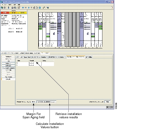
Figure B-2 Install Without MetroPlanner Tab

Step 5 Enter a value (in dB) in the Margin For Span Aging field. This value is subtracted from the near-end transmit power launch value to compensate for span aging.

Step 6 Click Calculate Installation Values. The following information appears for each side:

Result—Displays the results of the installation value retrieval:

Success—The ANS installation values were successfully calculated using values from the far-end node.

Fail—None of the ANS installation values were successfully retrieved.

Partial Fail—Some of the ANS installation values were successfully retrieved from the far-end node.

Near End Receiving Power—The SidenRx.Power Received ANS parameter value, where n = A through H.

Near End Transmitting Power—The SidenTx.Power Launch ANS parameter value, where n = A through H.

Step 7 If the Results column is Success for all sides, you have completed this procedure. If a Fail or Partial Fail result appears, review the information provided in the Note column:

No parameter was calculated—Click the Provisioning > WDM-ANS > Provisioning tabs to view information about the parameters that could not be calculated.

Some parameters were not calculated—Click the Provisioning > WDM-ANS > Provisioning tabs to view information about the parameters that could not be calculated.

The FE node was unreachable—Check the connectivity to the adjacent node. Complete the procedures listed in Step 2 to verify both the physical fiber and OSC connectivity to the far-end node.

Stop. You have completed this procedure.


hometocprevnextglossaryfeedbacksearchhelp

Posted: Mon Oct 29 01:39:03 PDT 2007
All contents are Copyright © 1992--2007 Cisco Systems, Inc. All rights reserved.
Important Notices and Privacy Statement.