cc/td/doc/product/ong/15400/r80docs
hometocprevnextglossaryfeedbacksearchhelp
PDF

Table Of Contents

Upgrade, Add, and Remove Cards and Nodes

Before You Begin

NTP-G107 Remove Permanently or Remove and Replace DWDM Cards

DLP-G254 Place Amplifier Ports Out of Service

DLP-G318 Place Amplifier Ports In Service

NTP-G127 Add an AD-xC-xx.x Card to an OADM Node

NTP-G129 Add a DWDM Node

NTP-G130 Remove a DWDM Node

NTP-G146 Add a Rack and/or Shelf to a Multishelf Node

NTP-G147 Delete a Shelf and/or Rack from a Multishelf Node

NTP-G173 Convert an OADM Node to a ROADM Node

NTP-G176 Convert an Line Amplifier Node to an OADM Node

NTP-G182 Convert a Line Amplifier Node to a ROADM Node

NTP-G195 Convert a Protected ROADM Node from two Separate Nodes to a Single Multishelf Node

NTP-G177 Upgrade ANS Parameters on a DWDM Node


Upgrade, Add, and Remove Cards and Nodes


Note The terms "Unidirectional Path Switched Ring" and "UPSR" may appear in Cisco literature. These terms do not refer to using Cisco ONS 15xxx products in a unidirectional path switched ring configuration. Rather, these terms, as well as "Path Protected Mesh Network" and "PPMN," refer generally to Cisco's path protection feature, which may be used in any topological network configuration. Cisco does not recommend using its path protection feature in any particular topological network configuration.


This chapter provides procedures for adding and removing dense wavelength division multiplexing (DWDM) cards and nodes.


Note Unless otherwise specified, "ONS 15454" refers to both ANSI and ETSI shelf assemblies.


Before You Begin

Before performing any of the following procedures, investigate all alarms and clear any trouble conditions. Refer to the Cisco ONS 15454 DWDM Troubleshooting Guide as necessary for general troubleshooting information and alarm or error descriptions.

This section lists the chapter procedures (NTPs). Turn to a procedure to view its tasks (DLPs).

1. G107 Remove Permanently or Remove and Replace DWDM Cards—Complete as needed.

2. G127 Add an AD-xC-xx.x Card to an OADM Node—Complete as needed.

3. G129 Add a DWDM Node—Complete as needed.

4. G130 Remove a DWDM Node—Complete as needed.

5. G146 Add a Rack and/or Shelf to a Multishelf Node—Complete as needed.

6. G147 Delete a Shelf and/or Rack from a Multishelf Node—Complete as needed.

7. G173 Convert an OADM Node to a ROADM Node—Complete as needed.

8. G176 Convert an Line Amplifier Node to an OADM Node—Complete as needed.

9. G182 Convert a Line Amplifier Node to a ROADM Node—Complete as needed.

10. G195 Convert a Protected ROADM Node from two Separate Nodes to a Single Multishelf Node—Complete as needed.

11. G177 Upgrade ANS Parameters on a DWDM Node—Complete as needed.

NTP-G107 Remove Permanently or Remove and Replace DWDM Cards

Purpose

This procedure permanently removes or removes and replaces DWDM cards installed in the ONS 15454 shelf and rack.

Tools/Equipment

None

Prerequisite Procedures

NTP-G30 Install the DWDM Cards, page 3-51

NTP-G179 Install the TXP, MXP, GE_XP, 10GE_XP, and ADM-10G Cards, page 3-56

Required/As Needed

As needed

Onsite/Remote

Onsite

Security Level

Provisioning or higher


Caution Removing and replacing cards can be traffic affecting.


Caution Do not use this procedure to replace a TCC2 or TCC2P card.


Step 1 Complete the "DLP-G46 Log into CTC" task.


Note If you cannot log into Cisco Transport Controller (CTC) and you need to remove a card, remove the card as described in Step 6. After you log into CTC, troubleshoot the mismatched equipment alarm (MEA) with the Cisco ONS 15454 DWDM Troubleshooting Guide.


Step 2 Click the Alarms tab.

a. Verify that the alarm filter is not on. See the "DLP-G128 Disable Alarm Filtering" task as necessary.

b. Verify that no unexplained alarms appear on the network. If alarms appear, investigate and resolve them before continuing. Refer to the Cisco ONS 15454 DWDM Troubleshooting Guide for procedures.

Step 3 If you are removing and replacing a card, go to Step 5.

Step 4 If you are permanently removing a card, go to Step 11.

Step 5 To remove and replace a card, complete the following tasks, as needed:

The circuits traversing through the card that needs to be replaced (for example, an amplifier) need to be protection switched. For instance, if the card you want to replace is an active transponder (TXP) or muxponder (MXP) in a Y-cable protection group, complete the "DLP-G179 Apply a Force Y-Cable or Splitter Protection Switch" task on page 10-43 to force traffic away from the TXP or MXP that you will remove. If the card you want to replace is the standby TXP or MXP in a Y-cable protection group, complete the "DLP-G182 Apply a Lockout" task on page 10-45 to prevent traffic from switching to the TXP or MXP that you will remove. See the Cisco ONS 15454 Procedure Guide or the Cisco ONS 15454 SDH Procedure Guide for other types of protection switching path protection, BLSR, optical, and electrical).

If the card is an OSCM or OSC-CSM that is used as a node timing reference, complete the "NTP-G112 Change the Node Timing Reference" procedure on page 13-18 to change the timing reference to a card that will not be removed.

If the card is an OSCM or OSC-CSM with an optical service channel (OSC) or generic communications channel (GCC) termination, complete the "NTP-G85 Modify or Delete OSC Terminations, GCC Terminations, and Provisionable Patchcords" procedure on page 10-47 to delete the termination and recreate it on a card that will not be removed.


Note If you delete a card in CTC but do not remove it from the shelf, it will reboot and reappear in CTC.


Step 6 Physically remove the card:

a. Disconnect any cables.

b. Open the card latches/ejectors.

c. Use the latches/ejectors to pull the card forward and away from the shelf.

Step 7 Insert the new card using one of the following procedures as applicable:

NTP-G30 Install the DWDM Cards, page 3-51

NTP-G179 Install the TXP, MXP, GE_XP, 10GE_XP, and ADM-10G Cards, page 3-56

Step 8 Complete the "NTP-G34 Install Fiber-Optic Cables on DWDM Cards and DCUs" procedure on page 3-63.

Step 9 Complete the following tasks or procedures, as needed:

If you switched a Y-cable protection group in Step 5, complete the "DLP-G180 Clear a Manual or Force Y-Cable or Splitter Protection Switch" task on page 10-44.

If you switched the timing reference in Step 5, complete the "NTP-G112 Change the Node Timing Reference" procedure on page 13-18 to change the reference back to the new card.

If you deleted an OSC or GCC termination in Step 5, complete the "NTP-G38 Provision OSC Terminations" procedure on page 3-98 or the "DLP-G76 Provision GCC Terminations" task.

Step 10 Go to Step 13.

Step 11 To permanently remove a card, complete the following tasks:

Delete the circuits associated with the card being removed. Complete the "DLP-G106 Delete Optical Channel Network Connections" task, the "DLP-G347 Delete Optical Channel Client Connections" task, or the "DLP-G418 Delete an Optical Channel Trail" task as needed.

Physically remove the card:

Disconnect any cables.

Open the card latches/ejectors.

Use the latches/ejectors to pull the card forward and away from the shelf.

Step 12 If the card you are removing is an OSCM, OSC-CSM, DWDM Amplifier, or Filter card, complete the following tasks; otherwise, go to Step 13.

Reconfigure the circuits (OCHCC, OCHNC, Trails) as needed. Complete the "DLP-G105 Provision Optical Channel Network Connections" task, the "DLP-G346 Provision Optical Channel Client Connections" task, or the "DLP-G395 Create an Optical Channel Trail" task.

Reload ANS provisioning. Complete the "NTP-G143 Import the Cisco MetroPlanner NE Update Configuration File" task on page 3-43.

Relaunch ANS. Complete the "NTP-G37 Run Automatic Node Setup" task on page 3-101.

Step 13 Click the Alarms tab.

a. Verify that the alarm filter is not on. See the "DLP-G128 Disable Alarm Filtering" task as necessary.

b. Verify that no unexplained alarms appear on the network. If alarms appear, investigate and resolve them. Refer to the Cisco ONS 15454 DWDM Troubleshooting Guide for procedures.

Stop. You have completed this procedure.


DLP-G254 Place Amplifier Ports Out of Service

Purpose

This task places OPT-BST, OPT-BST-E, OPT-BST-L, OPT-PRE, OPT-AMP-L, or OPT-AMP-17-C card ports out of service in preparation for card removal.

Tools/Equipment

None

Prerequisite Procedures

G46 Log into CTC

Required/As Needed

As needed

Onsite/Remote

Onsite or remote

Security Level

Provisioning or higher


Step 1 On the shelf graphic in CTC, double-click the OPT-BST, OPT-BST-E, OPT-BST-L, OPT-PRE, OPT-AMP-L, or OPT-AMP-17-C card with the ports that you want to put out of service.

Step 2 Click the Provisioning > Optical Line > Parameters tabs.

Step 3 In the Admin State column for the card's ports, choose OOS,MT (ANSI) or Locked,disabled (ETSI) for each port that does not have an OOS-MA,DSBLD or Locked-enabled,disabled service state.

Step 4 Click Apply.

Step 5 In the confirmation dialog box, click Yes.

Step 6 Click the Provisioning > Opt Apli Line > Parameters tabs.

Step 7 In the Admin State column for the card's ports, choose OOS,MT or IS,AINS (ANSI) or Locked,maintenance or unlocked,automaticinservice (ETSI) for each port that does not have an OOS-MA,DSBLD or Locked,disabled service state.

Step 8 Click Apply.

Step 9 In the confirmation dialog box, click Yes.

Step 10 Return to your originating procedure (NTP).


DLP-G318 Place Amplifier Ports In Service

Purpose

This task places OPT-BST, OPT-BST-E, OPT-BST-L, OPT-PRE, OPT-AMP-L or OPT-AMP-17-C card ports in service.

Tools/Equipment

None

Prerequisite Procedures

G46 Log into CTC

Required/As Needed

As needed

Onsite/Remote

Onsite or remote

Security Level

Provisioning or higher


Step 1 On the shelf graphic in CTC, double-click the OPT-BST, OPT-BST-E, OPT-BST-L, OPT-PRE, OPT-AMP-L, or OPT-AMP-17-C card with the ports that you want to put in service.

Step 2 Click the Provisioning > Optical Line > Parameters tabs.

Step 3 In the Admin State column for the card's ports, choose IS,AINS (ANSI) or Unlocked-automaticInService (ETSI) for Port 1 (COM-RX) of the OPT-PRE card (or OPT-AMP-L or OPT-AMP-17-C cards provisioned in OPT-PRE mode), or Port 2 (OSC-RX) and Port 3 (COM-TX) of the OPT-BST, OPT-BST-E, or OPT-BST-L cards (or OPT-AMP-L or OPT-AMP-17-C cards provisioned in OPT-LINE mode).

Step 4 Click Apply.

Step 5 In the confirmation dialog box, click Yes.

Step 6 Return to your originating procedure (NTP).


NTP-G127 Add an AD-xC-xx.x Card to an OADM Node

Purpose

This procedure adds an AD-xC-xx.x card to an optical add/drop multiplexing (OADM) node.

Tools/Equipment

None

Prerequisite Procedures

"Turn Up a Network"

A Cisco MetroPlanner OADM site plan recalculated for the new OADM card

Required/As Needed

As needed

Onsite/Remote

Onsite

Security Level

Provisioning or higher


Note Do not begin this procedure until the Cisco MetroPlanner site plan has been recalculated with the new AD-xC-xx.x card added to the OADM node.


Caution This procedure will affect the service of unprotected circuits that pass through the OADM node.


Step 1 Complete the "DLP-G46 Log into CTC" task at a node in the OADM network.

Step 2 In node view (single-shelf mode) or multishelf view (multishelf mode), display the OADM node where you will add the card.

Step 3 Click the Circuits tab.

Step 4 Make a list of all optical channel network connections (OCHNCs) and/or optical channel client connections (OCHCCs) that are carried on the express path for both the Side B-to-Side A and Side A-to-Side B directions.

Step 5 For OCHNCs and/or OCHCCs identified in Step 4 that are routed on the active path of a splitter or Y-cable protection group, force the traffic to the protect path in the opposite side of the ring using the "DLP-G179 Apply a Force Y-Cable or Splitter Protection Switch" task on page 10-43.

Step 6 Click the Circuits tab.

Step 7 Complete the following steps for all OCHNCs and/or OCHCCs carried on the express path that were identified in Step 4:

a. Choose the OCHNC or OCHCC circuit(s) and click Edit. (To choose multiple circuits, press the Shift key while you click the circuits.)

b. In the Edit Circuit dialog box, click the State tab.

c. In the State field on the right, choose OOS,DSBLD (ANSI) or Locked,disabled (ETSI) from the drop-down list.

d. Click Apply.

e. Repeat Steps a through d for each OCHNC or OCHCC circuit.

Step 8 From the Tools menu, choose Open TL1 Connection.

Step 9 In the Select Node dialog box, choose the OADM node where you will add the AD-xC-xx.x card and click OK.

Step 10 In the TL1 dialog box, use the DLT-OCHNC command to delete the OCHNC cross-connects for the express path OCHNC listed in Step 4, using the following format:

DLT-OCHNC:[<TID>]:<SRC>,<DST>:<CTAG>:::[CKTID=<CKTID>],[CMDMDE=<CMDMDE>];

where:

<SRC> is the access identifier from the Channel section in a two-way wavelength.

<DST> is the destination access identifier from the LINEWL section in a two-way wavelength.

<CKTID> is the cross-connect ID. The default is Blank or None. CKTD is a string of ASCII characters. The maximum length is 48. If CKTID is empty or null, the CKTID field will not be displayed.

<CMDMDE> is the command execution mode. NORM mode is the default behavior for all commands but you can specify FRCD to force the system to override a state in which the command would normally be denied.

For additional information, including valid command values, refer to the Cisco ONS SONET TL1 Command Guide or the Cisco ONS 15454 SDH and Cisco ONS 15600 SDH TL1 Command Guide.

Step 11 In the TL1 dialog box, use the DLT-OCHCC command to delete the OCHCC cross-connects for the express path OCHCC listed in Step 4, using the following format:

DLT-OCHCC:[<TID>]:<AID>:<CTAG>[:::CKTID=<CKTID>],[CMDMDE=<CMDMDE>];

where:

<AID> is the access identifier from the Channel section i in a two-way wavelength.

<CKTID> is the cross-connect ID. The default is Blank or None. CKTD is a string of ASCII characters. The maximum length is 48. If CKTID is empty or null, the CKTID field will not be displayed.

<CMDMDE> is the command execution mode. NORM mode is the default behavior for all commands but you can specify FRCD to force the system to override a state in which the command would normally be denied.

For additional information, including valid command values, refer to the Cisco ONS SONET TL1 Command Guide or the Cisco ONS 15454 SDH and Cisco ONS 15600 SDH TL1 Command Guide.

Step 12 Click Close to close the TL1 dialog box.

Step 13 In node view (single-shelf mode) or multishelf view (multishelf mode), click the Provisioning > WDM-ANS > Internal Patchcords tabs.

Step 14 Highlight the two express connections that carry the deleted circuits passing through the node. (The express connections are the only ones connecting an EXP_TX port on the last Side A OADM card, with an EXP_RX port on the first Side B OADM card.)

Step 15 Click Delete.

Step 16 Remove the physical express cables between the EXP_TX and EXP_RX ports specified in Step 14.

Step 17 Insert the new AD-xC-xx.x card in the slot identified by your Cisco MetroPlanner site plan.

Step 18 Complete the "NTP-G34 Install Fiber-Optic Cables on DWDM Cards and DCUs" procedure on page 3-63 for the OADM node, following the new internal connections table generated by Cisco MetroPlanner.

Step 19 Complete the "NTP-G152 Create and Verify Internal Patchcords" procedure on page 3-94.

Step 20 Import the recalculated OADM site parameters. See the "NTP-G143 Import the Cisco MetroPlanner NE Update Configuration File" task on page 3-43.

Step 21 In node view (single-shelf mode) or multishelf view (multishelf mode), click the Provisioning > WDM-ANS > Port Status tabs.

Step 22 Click Launch ANS.

Step 23 From the Tools menu, choose Open TL1 Connection.

Step 24 In the Select Node dialog box, choose the OADM node and click OK.

Step 25 In the TL1 dialog box, use the DLT-OCHNC command to delete the OCHNC cross-connects for the express path OCHNC listed in Step 14, using the following format:

DLT-OCHNC:[<TID>]:<SRC>,<DST>:<CTAG>:::[CKTID=<CKTID>],[CMDMDE=<CMDMDE>];

where:

<SRC> is the access identifier from the Channel section in a two-way wavelength.

<DST> is the destination access identifier from the LINEWL section in a two-way wavelength.

<CKTID> is the cross-connect ID. The default is Blank or None. CKTD is a string of ASCII characters. The maximum length is 48. If CKTID is empty or null, the CKTID field will not be displayed.

<CMDMDE> is the command execution mode. NORM mode is the default behavior for all commands but you can specify FRCD to force the system to override a state in which the command would normally be denied.

For additional information, including valid command values, refer to the Cisco ONS SONET TL1 Command Guide or the Cisco ONS 15454 SDH and Cisco ONS 15600 SDH TL1 Command Guide.

Step 26 In the TL1 dialog box, use the DLT-OCHCC command to delete the OCHCC cross-connects for the express path OCHCC listed in Step 14, using the following format:

DLT-OCHCC:[<TID>]:<AID>:<CTAG>[:::CKTID=<CKTID>], [CMDMDE=<CMDMDE>]

where:

<AID> is the access identifier from the Channel section.

<CKTID> is the cross-connect ID. The default is Blank or None. CKTD is a string of ASCII characters. The maximum length is 48. If CKTID is empty or null, the CKTID field will not be displayed.

<CMDMDE> is the command execution mode. NORM mode is the default behavior for all commands but you can specify FRCD to force the system to override a state in which the command would normally be denied.

<PST> is the Primary state, which indicates the current overall service condition of an entity. The default is IS (in service).

<SST> s the Secondary state, which provides additional information pertaining to PST and PSTQ. The default is AINS.

For additional information, including valid command values, refer to the Cisco ONS SONET TL1 Command Guide or the Cisco ONS 15454 SDH and Cisco ONS 15600 SDH TL1 Command Guide.

Step 27 Click Close to close the TL1 dialog box.

Step 28 In node view (single-shelf mode) or multishelf view (multishelf mode), click the Circuits tab.

Step 29 Complete the following steps for all OCHNCs and/or OCHCCs set to OOS,DSBLD (ANSI) or Locked,disabled (ETSI) in Step 7:

a. Choose the OCHNC or OCHCC circuit(s) and click Edit. To choose multiple circuits, press the Shift key while you click the circuits.

b. In the Edit Circuit dialog box, click the State tab.

c. In the State field on the right, choose IS,AINS (ANSI) or Unlocked,automaticInService (ETSI) from the drop-down list.

d. Click Apply, and then click OK.

Step 30 Complete the "DLP-G180 Clear a Manual or Force Y-Cable or Splitter Protection Switch" task on page 10-44 for OCHNCs and/or OCHCCs that were switched to the opposite side of the ring as part of a splitter or Y-cable protection group to return the traffic to its condition before the card was added.

Stop. You have completed this procedure.


NTP-G129 Add a DWDM Node

Purpose

This procedure adds a DWDM node to an existing DWDM network.

Tools/Equipment

None

Prerequisite Procedures

"Turn Up a Network"

A Cisco MetroPlanner network plan recalculated for the new node

Required/As Needed

As needed

Onsite/Remote

Onsite

Security Level

Provisioning or higher


Note Do not begin this procedure until the Cisco MetroPlanner network plan has been updated and recalculated with the new DWDM node.


Note This procedures assumes that all turn-up procedures provided in Chapter 3, "Turn Up a Node" have been completed at the node that will be added. If they have not been completed, do not continue. Complete the turn-up procedures at the new node before you complete this procedure.


Note During this procedure, you will use TL1 commands to delete and recreate OCHNC and OCHCC cross-connects. You might need to refer to the Cisco ONS SONET TL1 Command Guide or the Cisco ONS 15454 SDH and Cisco ONS 15600 SDH TL1 Command Guide.


Caution To complete this procedure, a span will be disconnected where the new node is added. This will affect the service of any unprotected circuits that pass through that span.


Step 1 At the node that will be added, complete the "G51 Verify DWDM Node Turn Up" procedure. If the node has not been turned up, do not continue. Complete the relevant procedures in Chapter 3, "Turn Up a Node" and Chapter 4, "Perform Node Acceptance Tests," then begin this procedure again.

Step 2 If the Cisco MetroPlanner network design has not been updated and recalculated for the new node and client services, update and recalculate it now, following the procedures in the Cisco MetroPlanner documentation.

Step 3 Identify the fiber spans that must be disconnected to insert the new node.

Step 4 Complete the "DLP-G46 Log into CTC" task at a DWDM node that is active on the network where you want to add the new DWDM node.

Step 5 From the View menu, choose Go to Network View.

Step 6 In network view, click the Circuits tab.

Step 7 Identify the OCHCCs and/or OCHNCs that are carried on the fiber span express path that you identified in Step 3 in both the Side B-to-Side A and Side A-to-Side B directions.

Step 8 If the OCHCC and/or OCHNC circuit is on the active path and is protected by a splitter or Y-cable protection group, complete the "DLP-G179 Apply a Force Y-Cable or Splitter Protection Switch" task on page 10-43 to force traffic away from the span where the node will be added. If not, continue with Step 9.

Step 9 For each circuit identified in Step 7 that was not switched in Step 8 (unprotected circuits), complete the following steps:

a. In network view, select the OCHNC and/or OCHCC circuit and click Edit.

b. In the Edit Circuit dialog box, click the State tab.

c. In the State field on the right, choose OOS,DSBLD (ANSI) or Locked,disabled (ETSI) from the drop-down list.

d. Click Apply, then click OK.

Step 10 Remove the fibers from the cards at the adjacent nodes that will connect to the new node.

Step 11 Install the fibers from the adjacent nodes that will connect to the new node using the "NTP-G34 Install Fiber-Optic Cables on DWDM Cards and DCUs" procedure on page 3-63.

Step 12 Update the ANS parameters at the adjacent nodes:

a. Display an adjacent node in node view.

b. Complete the "NTP-G143 Import the Cisco MetroPlanner NE Update Configuration File" procedure on page 3-43 to load the new NE Update file onto the node.

c. Complete the "NTP-G37 Run Automatic Node Setup" procedure on page 3-101 to recalculate the ANS parameters at the node.

d. Display the next adjacent node in node view.

e. Repeat Steps b and c for the second adjacent node.

Step 13 Display the new node in node view.

Step 14 Create cross-connects on the new node for all circuits identified in Step 7:

a. From the Tools menu, choose Open TL1 Connection.

b. In the Select Node dialog box, choose the new node and click OK.

c. In the TL1 dialog box, use the ENT-OCHNC and/or ENT-OCHCC command to create the OCHNC and/or OCHCC cross-connects for each unprotected pass-through circuit as follows:

ENT-OCHNC:[<TID>]:<SRC>,<DST>:<CTAG>::[<WCT>]:[CKTID=<CKTID>],
[CMDMDE=<CMDMDE>]:[<PST>[,<SST>]];

where:

<SRC> is the source access identifier from the CHANNEL section. In two-way wavelength connection sources, both directions need to be indicated.

<DST> is the destination access identifier from the LINE section. In two-way wavelength connection sources, both directions need to be indicated.

<WCT> is the wavelength connection type, either 1WAY or 2WAY. The default is 1WAY.

<CKTID> is the cross-connect ID. The default is Blank or None. CKTID is a string of ASCII characters. The maximum length is 48. If CKTID is empty or null the CKTID field will not be displayed.

<CMDMDE> is the command execution mode.

<PST> is the primary state, either IS or OOS.

<SST> is the secondary state.

ENT-OCHCC:[<TID>]:<AID>:<CTAG>[:::CKTID=<CKTID>], [CMDMDE=<CMDMDE>]:[<PST>[,<SST>]];

where:

<AID> is the access identifier from the Channel section.

<CKTID> is the cross-connect ID. The default is Blank or None. CKTD is a string of ASCII characters. The maximum length is 48. If CKTID is empty or null, the CKTID field will not be displayed.

<CMDMDE> is the command execution mode. NORM mode is the default behavior for all commands but you can specify FRCD to force the system to override a state in which the command would normally be denied.

<PST> is the Primary state, which indicates the current overall service condition of an entity. The default is IS (in service).

<SST> s the Secondary state, which provides additional information pertaining to PST and PSTQ. The default is AINS.

For additional information and a list of valid command values, see the Cisco ONS SONET TL1 Command Guide or the Cisco ONS 15454 SDH and Cisco ONS 15600 SDH TL1 Command Guide.

d. Click Close to close the TL1 dialog box.

e. Repeat Step 9 to change the circuits placed in OOS,DSBLD (ANSI) or Locked,disabled (ETSI) back in service by choosing IS-AINS (ANSI) or Unlocked,automaticInService (ETSI) in the State drop-down list.

Step 15 Complete the "DLP-G180 Clear a Manual or Force Y-Cable or Splitter Protection Switch" task on page 10-44 for the circuits that were switched in Step 8 to return the traffic to its original paths.

Step 16 Complete the "DLP-G105 Provision Optical Channel Network Connections" task to create new circuits.

Stop. You have completed this procedure.


NTP-G130 Remove a DWDM Node

Purpose

This procedure removes a node from a DWDM network.

Tools/Equipment

None

Prerequisite Procedures

"Turn Up a Network"

A Cisco MetroPlanner network plan recalculated for the new node

Required/As Needed

As needed

Onsite/Remote

Onsite

Security Level

Provisioning or higher


Note Do not begin this procedure until the Cisco MetroPlanner network plan has been updated and recalculated with the DWDM node removed.


Note During this procedure, you will use TL1 commands to delete and recreate OCHNC or OCHCC cross-connects. You might need to refer to the Cisco ONS SONET TL1 Command Guide or the Cisco ONS 15454 SDH and Cisco ONS 15600 SDH TL1 Command Guide.


Caution This procedure will affect the service of unprotected circuits that pass through the span where the node will be removed.


Step 1 If the Cisco MetroPlanner network design has not been updated and recalculated with the node removed, update and recalculate the design now, following the procedures in the Cisco MetroPlanner documentation.

Step 2 Complete the "DLP-G46 Log into CTC" task at the DWDM target node.

Step 3 Click the Circuits tab.

Step 4 Identify the OCHNCs and/or OCHCCs that pass through or are added and dropped at the node that will be removed (that is, the target node), in both the Side B-to-Side A and Side A-to-Side B directions.

Step 5 Complete the "DLP-G347 Delete Optical Channel Client Connections" task and/or the "DLP-G106 Delete Optical Channel Network Connections" task to delete OCHCCs and/or OCHNCs identified in Step 4 that terminate (add/drop) on the target DWDM node.

Step 6 If OCHNC and/or OCHCC circuits pass through the target node on the active path and are protected by a splitter or Y-cable protection group, navigate to a node connected to the target node and complete the "DLP-G179 Apply a Force Y-Cable or Splitter Protection Switch" task on page 10-43 to force the traffic away from the node that will be deleted. Otherwise, continue with Step 7.

Step 7 Complete the following steps for each circuit identified in Step 4 that was not deleted in Step 5 or switched in Step 6:

a. Select the OCHNCs or OCHCCs and click Edit.

b. In the Edit Circuit dialog box, click the State tab.

c. In the State field, choose OOS,DSBLD (ANSI) or Locked,disabled (ETSI) from the drop-down list.

d. Click Apply, then click OK.

Step 8 Delete the cross-connects on the target node for each circuit placed in the OOS-DSBLD or Locked,disabled state in Step 7:

a. From the Tools menu, choose Open TL1 Connection.

b. In the Select Node dialog box, select the new node and click OK.

c. In the TL1 dialog box, use the DLT-OCHNC command to delete the OCHNC cross-connects for each unprotected pass-through circuit as follows:

DLT-OCHNC:[<TID>]:<SRC>,<DST>:<CTAG>:::[CKTID=<CKTID>], [CMDMDE=<CMDMDE>];

where:

<SRC> is the source access identifier from the Channel section in a two-way wavelength.

<DST> is the destination access identifier from the LINEWL section in a two-way wavelength.

<CKTID> is the cross-connect ID. The default is Blank or None. CKTD is a string of ASCII characters. The maximum length is 48. If CKTID is empty or null, the CKTID field will not be displayed.

<CMDMDE> is the command execution mode. NORM mode is the default behavior for all commands but you can specify FRCD to force the system to override a state in which the command would normally be denied.

For additional information, including valid command values, refer to the Cisco ONS SONET TL1 Command Guide or the Cisco ONS 15454 SDH and Cisco ONS 15600 SDH TL1 Command Guide.

d. In the TL1 dialog box, use the DLT-OCHCC command to delete the OCHCC cross-connects for the express path OCHCC listed in Step 4, using the following format:

DLT-OCHCC:[<TID>]:<AID>:<CTAG>[:::CKTID=<CKTID>],

where:

<AID> is the access identifier from the Channel section.

<CKTID> is the cross-connect ID. The default is Blank or None. CKTD is a string of ASCII characters. The maximum length is 48. If CKTID is empty or null, the CKTID field will not be displayed.

<CMDMDE> is the command execution mode. NORM mode is the default behavior for all commands but you can specify FRCD to force the system to override a state in which the command would normally be denied.

<PST> is the Primary state, which indicates the current overall service condition of an entity. The default is IS (in service).

<SST> s the Secondary state, which provides additional information pertaining to PST and PSTQ. The default is AINS.

For additional information, including valid command values, refer to the Cisco ONS SONET TL1 Command Guide or the Cisco ONS 15454 SDH and Cisco ONS 15600 SDH TL1 Command Guide.

e. Click Close to close the TL1 dialog box.

Step 9 Remove the fibers from the target node, and reconnect the fibers to the adjacent nodes.

Step 10 Update the ANS parameters at the adjacent nodes:

a. Display an adjacent node in node view.

b. Complete the "NTP-G143 Import the Cisco MetroPlanner NE Update Configuration File" procedure on page 3-43 to load the new NE Update file onto the node.

c. Complete the "NTP-G37 Run Automatic Node Setup" procedure on page 3-101 to recalculate the ANS parameters at the node.

d. Display the next adjacent node in node view.

e. Repeat Steps b and c for the second adjacent node.

Step 11 Repeat Step 7 to change the circuits placed in OOS,DSBLD (ANSI) or Locked,disabled (ETSI) back in service by changing the Target Circuit Admin State field to IS-AINS (ANSI) or Unlocked,AutomaticInService (ETSI).

Step 12 Complete the "DLP-G180 Clear a Manual or Force Y-Cable or Splitter Protection Switch" task on page 10-44 for the OCHNCs and/or OCHCCs that were switched in Step 6.

Step 13 Complete the "DLP-G346 Provision Optical Channel Client Connections" task and/or the "DLP-G105 Provision Optical Channel Network Connections" task to recreate OCHCCs and/or OCHNCs identified in Step 4 that originated or terminated on the removed DWDM node. Choose the new DWDM node as the start/end (add/drop, respectively) for each circuit.

Stop. You have completed this procedure.


NTP-G146 Add a Rack and/or Shelf to a Multishelf Node

Purpose

This procedure adds a rack and/or subtending shelf to a multishelf node.

Tools/Equipment

None

Prerequisite Procedures

One of the following:

NTP-G145 Connect a Multishelf Node and Subtending Shelves to an MS-ISC-100T Card, page 1-82

NTP-G158 Connect a Multishelf Node and Subtending Shelves to a Catalyst 2950, page 1-84

Chapter 3, "Turn Up a Node"

Required/As Needed

As needed

Onsite/Remote

Onsite

Security Level

Provisioning or higher


Note Each shelf you want to add to a multishelf configuration must have network connectivity. For more information, see "Connect the PC and Log into the GUI."


Step 1 Complete the "DLP-G46 Log into CTC" task at the multishelf DWDM node where you want to add a shelf.

Step 2 To add a rack, in multishelf view right-click the gray area and choose Add Rack. If you do not need to add a rack, continue with Step 3.

Step 3 To add a shelf, in multishelf view right-click the white space inside the rack and choose Add Shelf.

Step 4 In the Shelf ID Selection dialog box, choose a shelf ID from the drop-down list.

Step 5 Click OK. The shelf appears in the multishelf view.

Step 6 Complete the "DLP-G46 Log into CTC" task at the subtending shelf.

Step 7 In multishelf view, click the Provisioning > General > Multishelf Config tabs.

Step 8 Click Enable as Subtended Shelf.

Step 9 From the Shelf ID drop-down list, choose the shelf ID that you created in Step 4.

Step 10 Click Apply.

Step 11 In the confirmation dialog box, click Yes to reboot the shelf. The CTC view changes to network view and the node icon changes to gray. (This might take several minutes.)

Step 12 If you are connecting the new subtending shelf to the Ethernet Adapter Panel (EAP), complete the following steps. If not, continue with Step 13.

a. Using a cross-over (CAT 5) LAN cable, plug one connector into the RJ-45 front panel port of the subtending shelf TCC2/TCC2P card in Slot 7 and plug the other end into the SSC port on the left patch panel.

b. Using a cross-over (CAT 5) LAN cable, plug one connector into the RJ-45 front panel port of the subtending shelf TCC2/TCC2P card in Slot 11 and plug the other end into the SSC port on the right patch panel.

Step 13 If you are connecting the subtending shelf to the Catalyst 2950 switch, complete the following steps. If not, continue with Step 14.

a. Plug one end of a cross-over (CAT-5) LAN cable into the RJ-45 front panel port of the subtending shelf TCC2/TCC2P card in Slot 7 and plug the other end into Port 2 of the first Catalyst 2950.

b. Plug one end of a cross-over (CAT-5) LAN cable into the RJ-45 front panel port of the subtending shelf TCC2/TCC2P card in Slot 11 and plug the other end into Port 2 of the backup Catalyst 2950.

Step 14 Repeat Steps 3 through 13 for each subtending shelf in the multishelf configuration.

Stop. You have completed this procedure.


NTP-G147 Delete a Shelf and/or Rack from a Multishelf Node

Purpose

This procedure deletes a shelf and/or rack from a multishelf node.

Tools/Equipment

None

Prerequisite Procedures

One of the following:

NTP-G145 Connect a Multishelf Node and Subtending Shelves to an MS-ISC-100T Card, page 1-82

NTP-G158 Connect a Multishelf Node and Subtending Shelves to a Catalyst 2950, page 1-84

Chapter 3, "Turn Up a Node"

Required/As Needed

As needed

Onsite/Remote

Onsite

Security Level

Provisioning or higher


Note You cannot delete a node controller shelf from a multishelf node configuration.


Step 1 Complete the "DLP-G46 Log into CTC" task at the multishelf DWDM node where you want to delete a shelf or rack. If you want to delete a shelf, continue with Step 2. If you want to delete a rack only, go to Step 9.

Step 2 Complete the following tasks, as needed:

If cards on the shelf carry unprotected circuits, you must delete the circuits. Complete the "DLP-G106 Delete Optical Channel Network Connections" task and/or the "DLP-G347 Delete Optical Channel Client Connections" task.

If cards use internal patchcords, complete the "DLP-G355 Delete an Internal Patchcord" task on page 3-97.

If OSCM or OSC-CSM cards with OSC or GCC terminations are on the shelf, complete the "NTP-G85 Modify or Delete OSC Terminations, GCC Terminations, and Provisionable Patchcords" procedure on page 10-47 to delete the terminations.

Put all ports in the Out-of-Service and Management, Disabled (OOS-MA,DSBLD) (ANSI) or Locked-enabled,disabled (ETSI) service state. For more information, see Chapter 11, "Change DWDM Card Settings."


Note It is not necessary to delete the cards from the shelf before deleting a shelf.


Step 3 From the View menu, choose Go to Parent View to return to multishelf view.

Step 4 Right-click the subtending shelf you want to delete and choose Delete Shelf.

Step 5 In the confirmation dialog box, click Yes.

Step 6 To return the deleted shelf to a single-shelf node, you must use the LCD panel:

a. Repeatedly press the Status button until Shelf Status appears.

b. Repeatedly press the Port button until Controller Status=MS Config appears.

c. Press Status again and press Port to set multishelf mode to MS=N.

d. Press Status to choose Done.

e. Repeatedly press Status until "Save and Reboot?" appears, and then press Slot to choose Apply. This reboots the shelf. A "Saving changes; TCC may reboot" message appears on the LCD.

Step 7 After the TCC2/TCC2P reboot is complete, complete the following steps to disconnect the removed subtending shelf from the patch panel or Catalyst 2950:

a. Remove the cross-over (CAT 5) LAN cable from the RJ-45 front panel port of the TCC2/TCC2P card in Slot 7.

b. Remove the cross-over (CAT 5) LAN cable from the RJ-45 front panel port of the TCC2/TCC2P card in Slot 11.

Step 8 Reconnect the shelf to the LAN through either the backplane or one of the RJ-45 front panel ports of the TCC2/TCC2P cards. For more information, see "Connect the PC and Log into the GUI."

Step 9 To delete an empty rack from the CTC window, right-click the gray area on the rack graphic and choose Delete Rack.

Stop. You have completed this procedure.


NTP-G173 Convert an OADM Node to a ROADM Node

Purpose

This procedure converts an OADM node to a ROADM node.

Tools/Equipment

None

Prerequisite Procedures

"Turn Up a Network"

A Cisco MetroPlanner site plan recalculated for the new ROADM node.

Required/As Needed

As needed

Onsite/Remote

Onsite

Security Level

Provisioning or higher


Note Do not begin this procedure until the Cisco MetroPlanner site plan has been recalculated with the new ROADM node. You will import the new NE Update file and run ANS to recalculate the ANS parameters. In addition, you will run ANS at the two adjacent nodes to recalculate the ANS parameters at those nodes.


Note During this procedure, you will use TL1 commands to delete and recreate OCHNC or OCHCC cross-connects. You might need to refer to the Cisco ONS SONET TL1 Command Guide or the Cisco ONS 15454 SDH and Cisco ONS 15600 SDH TL1 Command Guide.


Caution This procedure will affect the service of unprotected circuits that pass through the OADM node.


Step 1 Complete the "DLP-G46 Log into CTC" task at a node in the OADM network.

Step 2 In node view (single-shelf mode) or multishelf view (multishelf mode), display the OADM node that you will convert to a ROADM node.

Step 3 Click the Circuits tab.

Step 4 Make a list of the following OCHNCs and/or optical channel client connections (OCHCCs) that:

Terminate (add/drop) at the node.

Pass through the node on the express path for both the Side B-to-Side A and Side A-to-Side B directions.

Step 5 If OCHNCs and/or OCHCCs identified in Step 4 are routed on the active path of a splitter or Y-cable protection group, complete the following steps. If not, continue with Step 6.

a. Display the node containing the TXP, MXP, ADM-10G, GE_XP, 10GE_XP, or ITU-T line card with the Y-cable or splitter protection.

a. Force the traffic to the protect path in the opposite side of the ring using the "DLP-G179 Apply a Force Y-Cable or Splitter Protection Switch" task on page 10-43.

Step 6 In node view, display node that will be converted.

Step 7 Complete the "DLP-G347 Delete Optical Channel Client Connections" task and/or the "DLP-G106 Delete Optical Channel Network Connections" task to delete OCHCCs and/or OCHNCs identified in Step 4 that:

Terminate (add/drop) at the node.

Pass through the node on an unprotected express path for both the Side B-to-Side A and Side A-to-Side B directions.

Step 8 From the Tools menu, choose Open TL1 Connection.

Step 9 In the Select Node dialog box, choose the OADM node and click OK.

Step 10 In the TL1 dialog box, use the DLT-OCHNC command to delete the OCHNC cross-connects for the express path OCHNCs listed in Step 4, using the following format:

DLT-OCHNC:[<TID>]:<SRC>,<DST>:<CTAG>:::[CKTID=<CKTID>],[CMDMDE=<CMDMDE>];

where:

<SRC> is the source access identifier from the Channel section in a two-way wavelength.

<DST> is the destination access identifier from the LINEWL section in a two-way wavelength.

<CKTID> is the cross-connect ID. The default is Blank or None. CKTD is a string of ASCII characters. The maximum length is 48. If CKTID is empty or null, the CKTID field will not be displayed.

<CMDMDE> is the command execution mode. NORM mode is the default behavior for all commands but you can specify FRCD to force the system to override a state in which the command would normally be denied.

For additional information, including valid command values, refer to the Cisco ONS SONET TL1 Command Guide or the Cisco ONS 15454 SDH and Cisco ONS 15600 SDH TL1 Command Guide.

Step 11 In the TL1 dialog box, use the DLT-OCHCC command to delete the OCHCC cross-connects for the express path OCHCCs listed in Step 4, using the following format:

DLT-OCHCC:[<TID>]:<AID>:<CTAG>[:::CKTID=<CKTID>],[CMDMDE=<CMDMDE>];

where:

<AID> is the access identifier from the Facility section.

<CKTID> is the cross-connect ID. The default is Blank or None. CKTD is a string of ASCII characters. The maximum length is 48. If CKTID is empty or null, the CKTID field will not be displayed.

<CMDMDE> is the command execution mode. NORM mode is the default behavior for all commands but you can specify FRCD to force the system to override a state in which the command would normally be denied.

For additional information, including valid command values, refer to the Cisco ONS SONET TL1 Command Guide or the Cisco ONS 15454 SDH and Cisco ONS 15600 SDH TL1 Command Guide.

Step 12 Click Close to close the TL1 dialog box.

Step 13 Delete the internal patchcords:

a. In node view (single-shelf mode) or multishelf view (multishelf mode), click the Provisioning > WDM-ANS > Internal Patchcords tabs.

b. Highlight all of the internal patchcords.

c. Click Delete.

d. Click Yes on the confirmation dialog box.

Step 14 Delete the OSC terminations:

a. Click the Provisioning > Comm Channels > OSC tabs.

b. Highlight all of the OSC terminations.

c. Click Delete.

d. Click Yes on the confirmation dialog box.

Step 15 Remove the cables from all the AD-xC-xx.x and/or AD-xB-xx.x cards.

Step 16 Remove the AD-xC-xx.x and/or AD-xB-xx.x cards from the shelf.

Step 17 Remove any amplifier cards (OPT-BST, OPT-PRE) that are installed but not required in the ROADM node.

Step 18 Install the new ROADM cards in the slots identified by your Cisco MetroPlanner site plan using the "NTP-G30 Install the DWDM Cards" procedure on page 3-51.

Step 19 Complete the "NTP-G34 Install Fiber-Optic Cables on DWDM Cards and DCUs" procedure on page 3-63 for the ROADM node, following the new internal connections table generated by Cisco MetroPlanner.

Step 20 Complete the "NTP-G152 Create and Verify Internal Patchcords" procedure on page 3-94 to recreate the internal patchcords deleted in Step 13.

Step 21 Complete the "NTP-G38 Provision OSC Terminations" procedure on page 3-98 to recreate the OSC terminations deleted in Step 14.

Step 22 Import the recalculated ROADM site parameters using the "NTP-G143 Import the Cisco MetroPlanner NE Update Configuration File" task on page 3-43.

Step 23 Complete the "NTP-G37 Run Automatic Node Setup" procedure on page 3-101.

Step 24 Update the ANS parameters at the adjacent nodes:

a. Display an adjacent node in node view.

b. Complete the "NTP-G143 Import the Cisco MetroPlanner NE Update Configuration File" procedure on page 3-43 to load the new NE Update file onto the node.

c. Complete the "NTP-G37 Run Automatic Node Setup" procedure on page 3-101 to recalculate the ANS parameters at the node.

d. Display the next adjacent node in node view.

e. Repeat Steps b and c for the second adjacent node.

Step 25 Display the new ROADM node in node view.

Step 26 Recreate the OCHNCs and/or OCHCCs deleted in Step 7 using the following tasks:

G346 Provision Optical Channel Client Connections

G105 Provision Optical Channel Network Connections

Step 27 Complete the "DLP-G180 Clear a Manual or Force Y-Cable or Splitter Protection Switch" task on page 10-44 for OCHNCs and/or OCHCCs that were switched to the opposite side of the ring as part of a splitter or Y-cable protection group to return the traffic to its condition before the card was added.

Stop. You have completed this procedure.


NTP-G176 Convert an Line Amplifier Node to an OADM Node

Purpose

This procedure converts a full line amplifier node with OPT-PRE and OPT-BST cards installed on each side of the shelf to an OADM node.

Tools/Equipment

Cisco MetroPlanner reports and NE Update file for the new OADM node.

Prerequisite Procedures

"Turn Up a Network"

A Cisco MetroPlanner site plan recalculated for the new ROADM node.

Required/As Needed

As needed

Onsite/Remote

Onsite

Security Level

Provisioning or higher


Caution This procedure will affect the service of unprotected circuits that pass through the OADM node.


Caution This procedure applies to line amplifier nodes with OPT-BST and OPT-PRE cards installed on both sides of the shelf. If the line amplifier node has a different configuration, the upgrade might affect the adjacent nodes and require an update of their ANS parameters. If the line amplifier node is not a full line amplifier, contact your next level of support.


Step 1 Complete the "NTP-G139 Verify Cisco MetroPlanner Reports and Files" procedure on page 3-3 procedure to verify that you have the files and reports prepared by Cisco MetroPlanner for the OADM node.

Step 2 Complete the "DLP-G46 Log into CTC" task at the line amplifier node.

Step 3 Click the Circuits tab.

Step 4 Make a list of the OCHNCs, OCH trails, and OCHCCs that pass through the node on the express path for both the Side B-to-Side A and Side A-to-Side B directions.


Caution You will delete the optical channel circuits in the next step and use the list to recreate the circuits later. Do not proceed until you complete the circuit list.

Step 5 Delete the circuits identified in Step 4 using one or more of the following tasks:

G347 Delete Optical Channel Client Connections

G418 Delete an Optical Channel Trail

G106 Delete Optical Channel Network Connections

Step 6 Click the Provisioning > WDM-ANS > Internal Patchcords tabs.

Step 7 In the internal patchcords table, click the OPT-PRE COM-TX to OPT-BST COM-RX internal patchcord.

Step 8 Click Delete.

Step 9 On the confirmation dialog, click OK.

Step 10 Remove the physical fiber and attenuators, if present, that connect the COM-TX to COM-RX ports and COM-RX to COM-TX ports between the OPT-BST and OPT-PRE cards installed in Side B.

Step 11 Referring to the Cisco MetroPlanner Shelf Layout report, install the AD-xC-xx-x and/or AD-xB-xx.x cards on both Side B and Side A of the node.

Step 12 Referring to the Cisco MetroPlanner Internal Connections report, connect the fibers to the new AD-xC-xx-x and/or AD-xB-xx.x cards.

Step 13 Click Default Patchcords.

Step 14 Verify that the new internal patchcords are created for the physical cables connected to the new AD-xC-xx.x and AD-xB-xx.x card(s) in Step 12. If not, complete the "DLP-G354 Create an Internal Patchcord Manually" task on page 3-95 to manually create the internal patchcords.

Step 15 Complete the "NTP-G143 Import the Cisco MetroPlanner NE Update Configuration File" procedure on page 3-43.

Step 16 Complete the "NTP-G37 Run Automatic Node Setup" procedure on page 3-101.

Step 17 In node view, click the Circuits tab.

Step 18 Complete one or more of the following procedures to recreate circuits identified in Step 4 that will pass through the OADM node:

G105 Provision Optical Channel Network Connections

G346 Provision Optical Channel Client Connections

G395 Create an Optical Channel Trail


Note Cisco recommends that you recreate the circuits one at a time.


Step 19 Verify that each circuit appears on the Circuits table with a DISCOVERED status and an IS/Unlocked state. If not, complete Steps 17 and 18.

If the circuits still do not appear with a DISCOVERED status and IS/Unlocked state, contact your next level of support.

Step 20 Referring to the Cisco MetroPlanner Traffic Matrix report, repeat Steps 18 and 19 to create the new add/drop circuits at the node, as needed.

Stop. You have completed this procedure.


NTP-G182 Convert a Line Amplifier Node to a ROADM Node

Purpose

This procedure converts a line amplifier node with OPT-PRE and OPT-BST cards installed on each side of the shelf to an ROADM node.

Tools/Equipment

Cisco MetroPlanner reports and NE Update file for the new ROADM node.

Prerequisite Procedures

"Turn Up a Network"

A Cisco MetroPlanner site plan recalculated for the new ROADM node.

Required/As Needed

As needed

Onsite/Remote

Onsite

Security Level

Provisioning or higher


Caution This procedure will affect the service of unprotected circuits that pass through the ROADM node.


Caution This procedure applies to line amplifier nodes with OPT-BST and OPT-PRE cards installed on both sides of the shelf. If the line amplifier node has a different configuration, the upgrade might affect the adjacent nodes and require an update of their ANS parameters. If the line amplifier node is not a full line amplifier, contact your next level of support.


Step 1 Complete the "NTP-G139 Verify Cisco MetroPlanner Reports and Files" procedure on page 3-3 to verify that you have the files and reports prepared by Cisco MetroPlanner for the ROADM node.

Step 2 Complete the "DLP-G46 Log into CTC" task at the line amplifier node.

Step 3 Click the Circuits tab.

Step 4 Make a list of the following OCHNCs, OCH trails, and OCHCCs that pass through the node on the express path for both the Side B-to-Side A and Side A-to-Side B directions.


Caution You will delete the optical channel circuits in the next step and use the list to recreate the circuits later. Do not proceed until you complete the circuit list.

Step 5 Delete the circuits identified in Step 4 using one or more of the following tasks:

G347 Delete Optical Channel Client Connections

G418 Delete an Optical Channel Trail

G106 Delete Optical Channel Network Connections

Step 6 Click the Provisioning > WDM-ANS > Internal Patchcords tabs.

Step 7 In the internal patchcords table, click the OPT-PRE COM-TX to OPT-BST COM-RX internal patchcord.

Step 8 Click Delete.

Step 9 In the confirmation dialog box, click OK.

Step 10 Remove the physical fiber and attenuators, if present, that connect the COM-TX to COM-RX ports and COM-RX to COM-TX ports between the OPT-BST and OPT-PRE cards installed in Side B.

Step 11 Referring to the Cisco MetroPlanner Shelf Layout report, install one of the following sets of cards on both Side B and Side A of the node as described by the Cisco MetroPlanner NE Update file:

32WSS and 32DMX cards

32WSS-L and 32DMX-L cards

40-WSS-C and 40-DMX-C cards

Step 12 Referring to the Cisco MetroPlanner Internal Connections report, connect the fibers to the new wavelength selective switch and demultiplexer cards.

Step 13 Click Default Patchcords.

Step 14 Verify that the new internal patchcords are created for the physical cables connected to the new wavelength selective switch and demultiplexer cards in Step 12. If not, complete the "DLP-G354 Create an Internal Patchcord Manually" task on page 3-95 to manually create the internal patchcords.

Step 15 Complete the "NTP-G143 Import the Cisco MetroPlanner NE Update Configuration File" procedure on page 3-43.

Step 16 Complete the "NTP-G37 Run Automatic Node Setup" procedure on page 3-101.

Step 17 In node view, click the Circuits tab.

Step 18 Complete one or more of the following procedures to recreate circuits identified in Step 4 that will pass through the ROADM node:

G105 Provision Optical Channel Network Connections

G346 Provision Optical Channel Client Connections

G395 Create an Optical Channel Trail


Note Cisco recommends that you recreate the circuits one at a time.


Step 19 Verify that each circuit appears on the Circuits table with a DISCOVERED status and an IS/Unlocked state. If not, repeat Steps 17 and 18.

If the circuits still do not appear with a DISCOVERED status and IS/Unlocked state, contact your next level of support.

Step 20 Referring to the Cisco MetroPlanner Traffic Matrix report, repeat Steps 17 and 18 to create the new add/drop circuits at the node, as needed.

Stop. You have completed this procedure.


NTP-G195 Convert a Protected ROADM Node from two Separate Nodes to a Single Multishelf Node

Purpose

This procedure converts a protected ROADM node from two separate nodes to a single multishelf node.

Tools/Equipment

None.

Prerequisite Procedures

"Turn Up a Network"

A Cisco TransportPlanner site plan recalculated for the new node.

Required/As Needed

As needed

Onsite/Remote

Onsite

Security Level

Provisioning or higher


Caution This procedure will affect the service of unprotected circuits that pass through the ROADM node.


Caution This procedure applies to two ROADM nodes, where ROADM Node 1 has amplifier cards (such as, OPT-BST and OPT-PRE) or optical service channel cards (OSCM or OSC-CSM) installed on both the sides of the shelf and 40-WSS-C/40-DMX-C card (or the 32WSS/32DMX and 32WSS-L/32DMX-L cards) installed in Side A (Slots 1 through 6) and the ROADM Node 2 has amplifier cards (such as, OPT-BST and OPT-PRE) or optical service channel cards (OSCM or OSC-CSM) installed on both the sides of the shelf and 40-WSS-C/40-DMX-C card (or the 32WSS/32DMX and 32WSS-L/32DMX-L cards) installed in Side B (Slots 12 through 17).


Note In this procedure, ROADM Node 1 will be used as node controller and ROADM Node 2 will be added to the multishelf configuration as a subtending shelf.


Step 1 Complete the "NTP-G139 Verify Cisco MetroPlanner Reports and Files" procedure on page 3-3 to verify that you have the files and reports prepared by Cisco TransportPlanner for the ROADM nodes.

Step 2 Complete the "DLP-G46 Log into CTC" task at the ROADM Node 1. Figure 12-1 shows the shelf view of ROADM Node 1 and Figure 12-2 shows the functional view of ROADM Node 1.

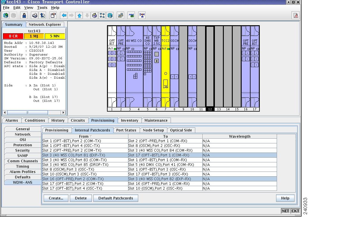
Figure 12-1 ROADM Node 1 Shelf View

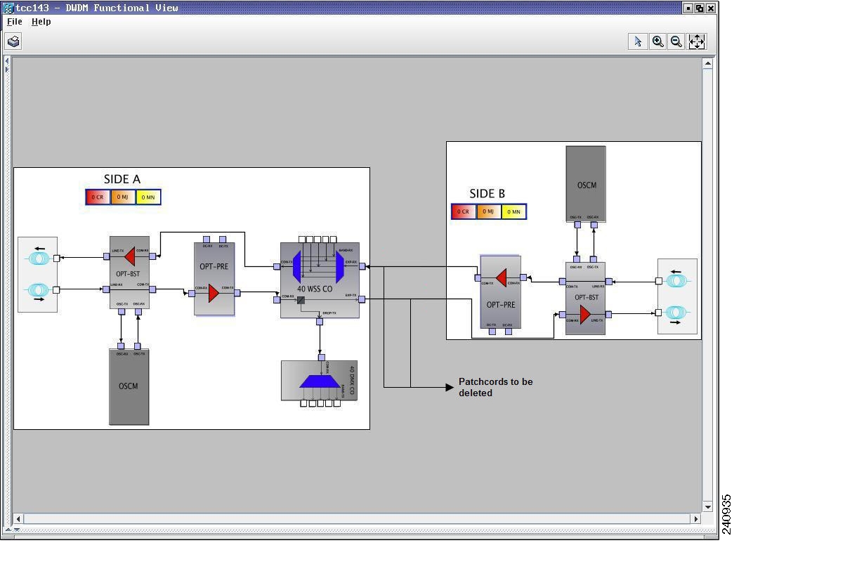
Figure 12-2 ROADM Node 1 Functional View

Step 3 Click the Circuits tab.

Step 4 Make a list of all the OCHNCs, OCH trails, and OCHCCs that pass through or terminate (add/drop) at the amplifier or optical service channel cards installed in Side B of ROADM Node 1.


Caution You will delete only the pass-through circuits in the next step and use the list to recreate the circuits later. Do not proceed until you complete the circuit list. The add/drop circuits will not be deleted and continues to transport traffic.

Step 5 If OCHNCs and/or OCHCCs identified in Step 4 are routed on the active path of a splitter or Y-cable protection group, complete the following steps. If not, continue with Step 6.

a. Display the node containing the amplifier or optical service channel cards with the Y-cable or splitter protection.

b. Force the traffic to the protect path in the opposite side of the ring using the "DLP-G179 Apply a Force Y-Cable or Splitter Protection Switch" task on page 10-43.

Step 6 Delete the circuits identified in Step 4 using one or more of the following tasks:

G347 Delete Optical Channel Client Connections

G418 Delete an Optical Channel Trail

G106 Delete Optical Channel Network Connections

Step 7 Click the Provisioning > WDM-ANS > Optical Side tab.

Step 8 In the optical sides table, click the optical side corresponding to the amplifier or optical service channel cards installed in Side B of ROADM Node 1.

Step 9 Click Delete.

Step 10 In the confirmation dialog box, click Yes.

Step 11 Click the Provisioning > WDM-ANS > Internal Patchcords tab.

Step 12 Look in the To column of the internal patchcords table and make a list of internal patchcords that connect the amplifier or optical service channel cards in Side B to the 40-WSS-C/40-DMX-C card (or the 32WSS/32DMX and 32WSS-L/32DMX-L cards) in Side A of ROADM Node 1.

Step 13 Click Delete.

Step 14 In the confirmation dialog box, click Yes.

Step 15 Remove the physical fiber and attenuators, if present, that connect the amplifier or optical service channel cards in Side B to the 40-WSS-C/40-DMX-C card (or the 32WSS/32DMX and 32WSS-L/32DMX-L cards) in Side A of ROADM Node 1.

Step 16 Complete the G107 Remove Permanently or Remove and Replace DWDM Cards to delete the amplifier or optical service channel cards installed in Side B of ROADM Node 1.

Step 17 Complete the "DLP-G46 Log into CTC" task at the ROADM Node 2. Figure 12-1 shows the ROADM Node 2 shelf view and Figure 12-4 shows the functional view of ROADM Node 1.

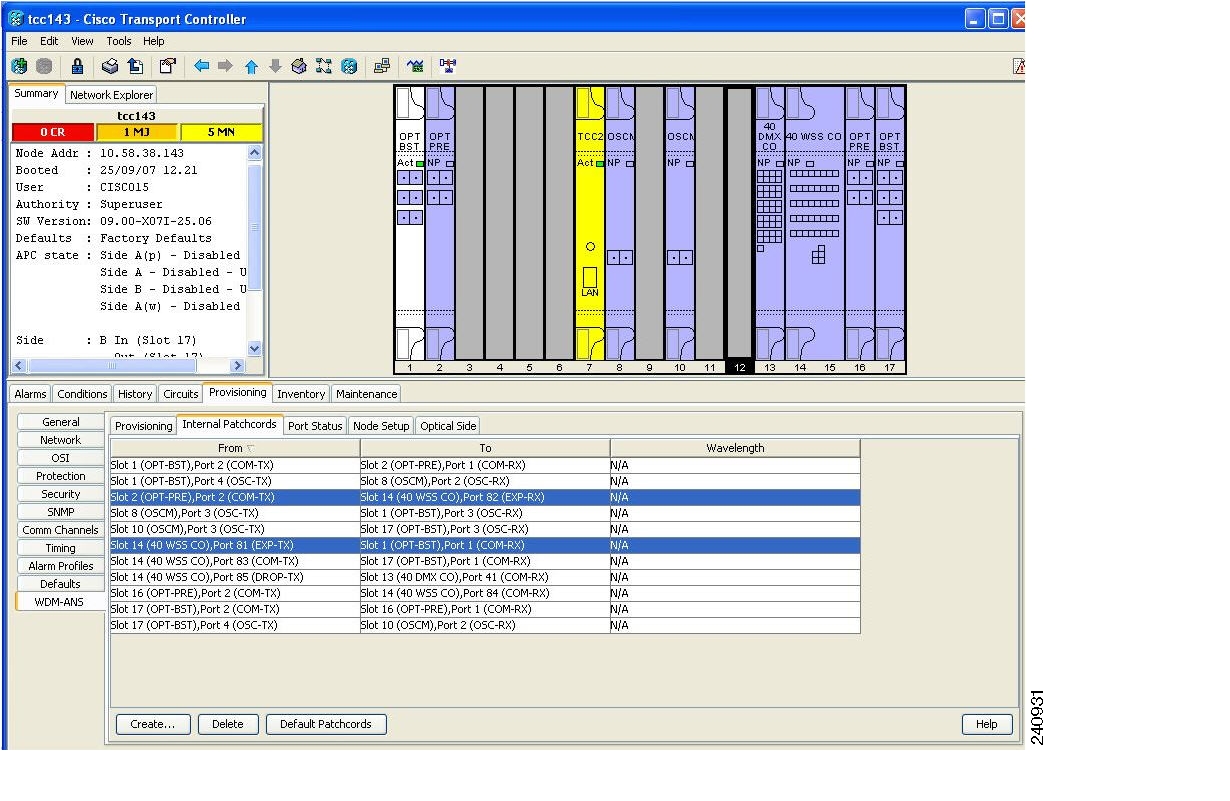
Figure 12-3 ROADM Node 2 Shelf View

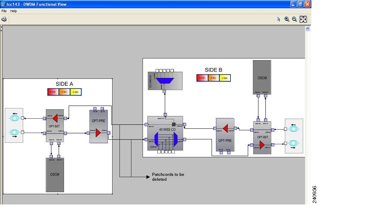
Figure 12-4 ROADM Node 2 Functional View

Step 18 Click the Circuits tab.

Step 19 Make a list of all the OCHNCs, OCH trails, and OCHCCs that pass through or terminate (add/drop) at the amplifier or optical service channel cards installed in Side A of ROADM Node 2.


Caution You will delete all the pass-through and add/drop circuits in the next step and use the list to recreate the circuits later. Do not proceed until you complete the circuit list.

Step 20 If OCHNCs and/or OCHCCs identified in Step 19 are routed on the active path of a splitter or Y-cable protection group, complete the following steps. If not, continue with Step 21.

a. Display the node containing the amplifier or optical service channel cards with the Y-cable or splitter protection.

b. Force the traffic to the protect path in the opposite side of the ring using the "DLP-G179 Apply a Force Y-Cable or Splitter Protection Switch" task on page 10-43.

Step 21 Delete the circuits identified in Step 19 using one or more of the following tasks:

G347 Delete Optical Channel Client Connections

G418 Delete an Optical Channel Trail

G106 Delete Optical Channel Network Connections

Step 22 If overhead circuits exist in the amplifier or optical service channel cards installed in Side A of ROADM Node 2, complete "DLP-G112 Delete Overhead Circuits" task to delete these overhead circuits.

Step 23 Click the Provisioning > WDM-ANS > Optical Side tab.

Step 24 In the optical sides table, click the optical side corresponding to the amplifier or optical service channel cards installed in Side A of ROADM Node 2.

Step 25 Click Delete.

Step 26 In the confirmation dialog box, click Yes.

Step 27 Click the Provisioning > WDM-ANS > Internal Patchcords tab.

Step 28 Look in the To column of the internal patchcords table and make a list of internal patchcords that connect the amplifier or optical service channel cards in Side A to the 40-WSS-C/40-DMX-C card (or the 32WSS/32DMX and 32WSS-L/32DMX-L cards) in Side B of ROADM Node 2.

Step 29 Click Delete.

Step 30 In the confirmation dialog box, click Yes.

Step 31 Remove the physical fiber and attenuators, if present, that connect the amplifier or optical service channel cards in Side A to the 40-WSS-C/40-DMX-C card (or the 32WSS/32DMX and 32WSS-L/32DMX-L cards) in Side B of ROADM Node 2.

Step 32 If there are pluggable port modules (PPMs) that terminate on the ROADM Node 2, complete the "DLP-G280 Delete a PPM" task to delete these PPMs.

Step 33 Complete the G107 Remove Permanently or Remove and Replace DWDM Cards to delete the amplifier or optical service channel cards installed in Side A of ROADM Node 2.

Step 34 Complete the NTP-G163 Upgrade Nodes in Single-Shelf Mode to Multishelf Mode, page 3-107 to upgrade ROADM Node 1 to a multishelf configuration and add ROADM Node 2 as a subtending shelf. Figure 12-5 shows the final multishelf view of the node.

Figure 12-5 Final Multishelf View of the Node

Step 35 In the multishelf view, click the Provisioning > WDM-ANS > Internal Patchcords tab.

Step 36 Click Create. The Internal Patchcord Creation wizard appears.

Step 37 In the Internal Patchcord Attributes page, choose OTS/OCH to OTS/OCH option and select the Bidirectional checkbox.

Step 38 Click Next.

Step 39 In the Internal Patchcord Origination page, provision the internal patchcord origination parameters.

Shelf—Choose the shelf where the internal patchcord originates.

Slot—Choose one of the two 40-WSS-C card (or the 32WSS/32DMX and 32WSS-L/32DMX-L cards) where the internal patchcord originates.

Tx Port—Choose the EXP TX port were the internal patchcord originates.

Step 40 Click Next.

Step 41 In the Internal Patchcord Termination page, provision the internal patchcord origination parameters.

Shelf—Choose the shelf where the internal patchcord terminates.

Slot—Choose the other 40-WSS-C card (or the 32WSS/32DMX and 32WSS-L/32DMX-L cards) where the internal patchcord terminates.

Rx Port—Choose the EXP RX port were the internal patchcord terminates.

Step 42 Click Next.

Step 43 Review the display-only information on the Internal Patchcord Origination Reverse page. This page shows the shelf, slot, and port that CTC will use for the opposite internal patchcord origination route.

Step 44 Click Next.

Step 45 Review the information displayed on the Internal Patchcord Termination Reverse page. This display-only page shows the shelf, slot, and port that CTC will use for the reverse internal patchcord termination route.

Step 46 Click Finish. The new internal patchcord appears on the Internal Patchcord table.

Step 47 Complete the "NTP-G37 Run Automatic Node Setup" procedure on page 3-101.

Step 48 In node view, click the Circuits tab.

Step 49 Complete one or more of the following procedures to recreate circuits identified in Steps 4 and 19:

G105 Provision Optical Channel Network Connections

G346 Provision Optical Channel Client Connections

G395 Create an Optical Channel Trail


Note Cisco recommends that you recreate the circuits one at a time.


Step 50 Complete the "G60 Create and Delete Overhead Circuits" procedure to recreate circuits deleted in Step 22.

Step 51 Verify that each circuit appears on the Circuits table with a DISCOVERED status and an IS/Unlocked state. If not, repeat Steps 48 and 49.

If the circuits still do not appear with a DISCOVERED status and IS/Unlocked state, contact your next level of support.

Step 52 Click the Provisioning > Pluggable Port Module > Pluggable Port Module tab and click Create to recreate the PPMs deleted in Step 32.

Step 53 Complete the "DLP-G180 Clear a Manual or Force Y-Cable or Splitter Protection Switch" task on page 10-44 for OCHNCs and/or OCHCCs that were switched to the opposite side of the ring as part of a splitter or Y-cable protection group to return the traffic to its original condition.

Stop. You have completed this procedure.


NTP-G177 Upgrade ANS Parameters on a DWDM Node

Purpose

This procedure upgrades the ANS parameters on a DWDM node.

Tools/Equipment

None

Prerequisite Procedures

Chapter 3, "Turn Up a Node"

An updated Cisco MetroPlanner NE Update file recalculated for the node.

Required/As Needed

As needed

Onsite/Remote

Onsite

Security Level

Provisioning or higher


Note Do not begin this procedure until the Cisco MetroPlanner NE Update file is prepared for the node. You will import the new NE Update file and run ANS to recalculate the ANS parameters for the node.


Caution Upgrading ANS parameters at one node requires ANS upgrades at all other nodes within the same network. Do not begin this procedure until you are not prepared to complete the upgrade at all network nodes.


Caution This procedure will affect the service of unprotected circuits that pass through the node.


Step 1 Complete the "DLP-G46 Log into CTC" task at the node you want to update.

Step 2 Click the Circuits tab.

Step 3 Make a list of the OCHCCs, OCHNCs, and OCH trails that:

Terminate (add/drop) at the node.

Pass through the node on the express path for both the Side B-to-Side A and Side A-to-Side B directions.

Step 4 If OCHNCs, OCH trails, and/or OCHCCs identified in Step 3 are routed on the active path of a splitter or Y-cable protection group, complete the following steps. If not, continue with Step 5.

a. Display the node containing the TXP, MXP, ADM-10G, GE_XP, 10GE_XP, or ITU-T line card with the Y-cable or splitter protection.

a. Force the traffic to the protect path in the opposite side of the ring using the "DLP-G179 Apply a Force Y-Cable or Splitter Protection Switch" task on page 10-43.

Step 5 For each circuit identified in Step 3 that was not switched in Step 4, place the circuit out of service using one or more of the following tasks.

G394 Change an OCHCC Administrative State

G419 Change an OCH Trail Administrative State

G420 Change an OCHNC Administrative State

Step 6 Complete the "NTP-G143 Import the Cisco MetroPlanner NE Update Configuration File" procedure on page 3-43.

Step 7 Complete the "NTP-G37 Run Automatic Node Setup" procedure on page 3-101.

Step 8 In node view, click the Circuits tab.

Step 9 If you placed circuits out of service in Step 5, complete one or more of the following tasks to put them in service.

G394 Change an OCHCC Administrative State

G419 Change an OCH Trail Administrative State

G420 Change an OCHNC Administrative State

Step 10 Verify that each circuit appears on the Circuits table with a DISCOVERED status and an IS/Unlocked state. If not, complete one or more of the following tasks to recreate the circuits.

"DLP-G105 Provision Optical Channel Network Connections" task

"DLP-G346 Provision Optical Channel Client Connections" task

"DLP-G395 Create an Optical Channel Trail" task


Note Cisco recommends that you recreate the circuits one at a time.


If the circuits still do not appear with a DISCOVERED status and IS/Unlocked state, contact your next level of support.

Stop. You have completed this procedure.


hometocprevnextglossaryfeedbacksearchhelp

Posted: Mon Oct 29 01:24:59 PDT 2007
All contents are Copyright © 1992--2007 Cisco Systems, Inc. All rights reserved.
Important Notices and Privacy Statement.