|
|

Table Of Contents
4.2 OC3 IR 4/STM1 SH 1310 Card
4.2.1 OC3 IR 4/STM1 SH 1310 Card-Level Indicators
4.2.2 OC3 IR 4/STM1 SH 1310 Port-Level Indicators
4.3 OC3 IR/STM1 SH 1310-8 Card
4.3.1 OC3 IR/STM1 SH 1310-8 Card-Level Indicators
4.3.2 OC3 IR/STM1 SH 1310-8 Port-Level Indicators
4.4.1 OC12 IR/STM4 SH 1310 Card-Level Indicators
4.4.2 OC12 IR/STM4 SH 1310 Port-Level Indicators
4.5.1 OC12 LR/STM4 LH 1310 Card-Level Indicators
4.5.2 OC12 LR/STM4 LH 1310 Port-Level Indicators
4.6.1 OC12 LR/STM4 LH 1550 Card-Level Indicators
4.6.2 OC12 LR/STM4 LH 1550 Port-Level Indicators
4.7 OC12 IR/STM4 SH 1310-4 Card
4.7.1 OC12 IR/STM4 SH 1310-4 Card-Level Indicators
4.7.2 OC12 IR/STM4 SH 1310-4 Port-Level Indicators
4.8.1 OC48 IR 1310 Card-Level Indicators
4.8.2 OC48 IR 1310 Port-Level Indicators
4.9.1 OC48 LR 1550 Card-Level Indicators
4.9.2 OC48 LR 1550 Port-Level Indicators
4.10 OC48 IR/STM16 SH AS 1310 Card
4.10.1 OC48 IR/STM16 SH AS 1310 Card-Level Indicators
4.10.2 OC48 IR/STM16 SH AS 1310 Port-Level Indicators
4.11 OC48 LR/STM16 LH AS 1550 Card
4.11.1 OC48 LR/STM16 LH AS 1550 Card-Level Indicators
4.11.2 OC48 LR/STM16 LH AS 1550 Port-Level Indicators
4.12 OC48 ELR/STM16 EH 100 GHz Cards
4.12.1 OC48 ELR 100 GHz Card-Level Indicators
4.12.2 OC48 ELR 100 GHz Port-Level Indicators
4.13.1 OC48 ELR 200 GHz Card-Level Indicators
4.13.2 OC48 ELR 200 GHz Port-Level Indicators
4.14 OC192 SR/STM64 IO 1310 Card
4.14.1 OC192 SR/STM64 IO 1310 Card-Level Indicators
4.14.2 OC192 SR/STM64 IO 1310 Port-Level Indicators
4.15 OC192 IR/STM64 SH 1550 Card
4.15.1 OC192 IR/STM64 SH 1550 Card-Level Indicators
4.15.2 OC192 IR/STM64 SH 1550 Port-Level Indicators
4.16 OC192 LR/STM64 LH 1550 Card
4.16.1 OC192 LR/STM64 LH 1550 Card-Level Indicators
4.16.2 OC192 LR/STM64 LH 1550 Port-Level Indicators
4.17 OC192 LR/STM64 LH ITU 15xx.xx Card
4.17.1 OC192 LR/STM64 LH ITU 15xx.xx Card-Level Indicators
4.17.2 OC192 LR/STM64 LH ITU 15xx.xx Port-Level Indicators
4.18 15454_MRC-12 Multirate Card
4.18.1 Slot Compatibility by Cross-Connect Card
4.18.3 15454_MRC-12 Card-Level Indicators
4.18.4 15454_MRC-12 Port-Level Indicators
4.19 OC192SR1/STM64IO Short Reach and OC192/STM64 Any Reach Cards
4.19.1 OC192SR1/STM64IO Short Reach and OC192/STM64 Any Reach Card-Level Indicators
4.19.2 OC192SR1/STM64IO Short Reach and OC-192/STM-64 Any Reach Port-Level Indicators
4.20 Optical Card SFPs and XFPs
Optical Cards
Note
The terms "Unidirectional Path Switched Ring" and "UPSR" may appear in Cisco literature. These terms do not refer to using Cisco ONS 15xxx products in a unidirectional path switched ring configuration. Rather, these terms, as well as "Path Protected Mesh Network" and "PPMN," refer generally to Cisco's path protection feature, which may be used in any topological network configuration. Cisco does not recommend using its path protection feature in any particular topological network configuration.
This chapter describes the Cisco ONS 15454 optical card features and functions. It includes descriptions, hardware specifications, and block diagrams for each optical card. For installation and card turn-up procedures, refer to the Cisco ONS 15454 Procedure Guide.
Chapter topics include:
•
•
•
•
•
4.1 Optical Card Overview
Each card is marked with a symbol that corresponds to a slot (or slots) on the ONS 15454 shelf assembly. The cards are then installed into slots displaying the same symbols. See the "1.17 Cards and Slots" section on page 1-60 for a list of slots and symbols.
4.1.1 Card Summary
Table 4-1 lists the Cisco ONS 15454 optical cards.
Table 4-1 Optical Cards for the ONS 15454
The OC3 IR 4 SH 1310 card provides four intermediate- or short-range OC-3 ports and operates at 1310 nm.
Note
See the "OC3 IR 4/STM1 SH 1310 Card" section.
The OC3 IR 4/STM1 SH 1310 card provides four intermediate- or short-range OC-3 ports and operates at 1310 nm.
See the "OC3 IR 4/STM1 SH 1310 Card" section.
The OC3 IR/STM1 SH 1310-8 card provides eight intermediate- or short-range OC-3 ports and operates at 1310 nm.
See the "OC3 IR/STM1 SH 1310-8 Card" section.
The OC12 IR 1310 card provides one intermediate- or short-range OC-12 port and operates at 1310 nm.
Note
See the "OC12 IR/STM4 SH 1310 Card" section.
The OC12 IR/STM4 SH 1310 card provides one intermediate- or short-range OC-12 port and operates at 1310 nm.
See the "OC12 IR/STM4 SH 1310 Card" section.
The OC12 LR 1310 card provides one long-range OC-12 port and operates at 1310 nm.
Note
See the "OC12 LR/STM4 LH 1310 Card" section.
The OC12 LR/STM4 LH 1310 card provides one long-range OC-12 port and operates at 1310 nm.
See the "OC12 LR/STM4 LH 1310 Card" section.
The OC12 LR 1550 card provides one long-range OC-12 port and operates at 1550 nm.
Note
See the "OC12 LR/STM4 LH 1550 Card" section.
The OC12 LR/STM4 LH 1550 card provides one long-range OC-12 port and operates at 1550 nm.
See the "OC12 LR/STM4 LH 1550 Card" section.
The OC12 IR/STM4 SH 1310-4 card provides four intermediate- or short-range OC-12 ports and operates at 1310 nm.
The OC48 IR 1310 card provides one intermediate-range OC-48 port and operates at 1310 nm.
See the "OC48 IR 1310 Card" section.
The OC48 LR 1550 card provides one long-range OC-48 port and operates at 1550 nm.
See the "OC48 LR 1550 Card" section.
The OC48 IR/STM16 SH AS 1310 card provides one intermediate- or short-range OC-48 port at 1310 nm.
The OC48 LR/STM16 LH AS 1550 card provides one long-range OC-48 port at 1550 nm.
The OC48 ELR/STM16 EH 100 GHz card provides one long-range (enhanced) OC-48 port and operates in Slot 5, 6, 12, or 13. This card is available in 18 different wavelengths (9 in the blue band and 9 in the red band) in the 1550-nm range, every second wavelength in the ITU grid for 100-GHz spacing dense wavelength division multiplexing (DWDM).
The OC48 ELR 200 GHz card provides one long-range (enhanced) OC-48 port and operates in Slot 5, 6, 12, or 13. This card is available in 18 different wavelengths (9 in the blue band and 9 in the red band) in the 1550-nm range, every fourth wavelength in the ITU grid for 200-GHz spacing DWDM.
See the "OC48 ELR 200 GHz Cards" section.
The OC192 SR/STM64 IO 1310 card provides one intra-office-haul OC-192 port at 1310 nm.
The OC192 IR/STM64 SH 1550 card provides one intermediate-range OC-192 port at 1550 nm.
The OC192 LR/STM64 LH 1550 card provides one long-range OC-192 port at 1550 nm.
The OC192 LR/STM64 LH ITU 15xx.xx card provides one extended long-range OC-192 port. This card is available in multiple wavelengths in the 1550-nm range of the ITU grid for 100-GHz-spaced DWDM.
The 15454_MRC-12 card provides up to twelve OC-3 or OC-12 ports, or up to four STM-16 ports, using dense wave division multiplexing (DWDM) SFPs. The card operates in Slots 1 to 6 and 12 to 17.
The OC192SR1/STM64IO Short Reach and OC192/STM64 Any Reach cards each provide a single OC-192/STM-64 interface capable of operating with SR-1, IR-2, and LR-2 XFP modules (depending on the card) at 1310 nm and 1550 nm. The cards operate in Slot 5, 6, 12, or 13 with the XC10G and XC-VXC-10G cards.
See the "OC192SR1/STM64IO Short Reach and OC192/STM64 Any Reach Cards" section.
1 In the Cisco Transport Controller (CTC) GUI, these cards are known as OC192-XFP.
Note
Corning MetroCor fiber is optimized for optical interfaces that transmit at 1550 nm or in the C and L DWDM windows, and targets interfaces with higher dispersion tolerances than those found in OC3 IR/STM1 SH, OC12 IR/STM4 SH, and OC48 IR/STM16 SH interface optics. If you are using Corning MetroCor fiber, OC3 IR/STM1 SH, OC12 IR/STM4 SH, and OC48 IR/STM16 SH interface optics become dispersion limited before they become attenuation limited. In this case, consider using OC12 LR/STM4 LH and OC48 LR/STM16 LH cards instead of OC12 IR/STM4 SH and OC48 IR/STM16 SH cards.
With all fiber types, network planners/engineers should review the relative fiber type and optics specifications to determine attenuation, dispersion, and other characteristics to ensure appropriate deployment.4.1.2 Card Compatibility
Table 4-2 lists the CTC software compatibility for each optical card. See Table 2-5 on page 2-4 for a list of cross-connect cards that are compatible with each optical card.
Note
Table 4-2 Optical Card Software Release Compatibility
Yes
Yes
Yes
Yes
Yes
Yes
Yes
Yes
—
Yes
—
Yes
Yes
Yes
Yes
Yes
Yes
Yes
Yes
Yes
Yes
Yes
Yes
—
Yes
—
Yes
Yes
Yes
Yes
—
—
—
—
—
—
Yes
Yes
—
Yes
—
Yes
Yes
Yes
Yes
Yes
Yes
Yes
Yes
Yes
Yes
Yes
Yes
—
Yes
—
Yes
Yes
Yes
Yes
Yes
Yes
Yes
Yes
Yes
Yes
Yes
Yes
—
Yes
—
Yes
Yes
Yes
Yes
Yes
Yes
Yes
Yes
Yes
Yes
Yes
Yes
—
Yes
—
Yes
Yes
Yes
Yes
Yes
Yes
Yes
Yes
Yes
Yes
Yes
Yes
—
Yes
—
Yes
Yes
Yes
Yes
Yes
Yes
Yes
Yes
Yes
Yes
Yes
Yes
—
Yes
—
Yes
Yes
Yes
Yes
Yes
Yes
Yes
Yes
Yes
Yes
Yes
Yes
—
Yes
—
Yes
Yes
Yes
Yes
—
—
—
—
Yes
Yes
Yes
Yes
—
Yes
—
Yes
Yes
Yes
Yes
Yes
Yes
Yes
Yes
Yes
Yes
Yes
Yes
—
Yes
—
Yes
Yes
Yes
Yes
Yes
Yes
Yes
Yes
Yes
Yes
Yes
Yes
—
Yes
—
Yes
Yes
Yes
Yes
—
—
Yes
Yes
Yes
Yes
Yes
Yes
—
Yes
—
Yes
Yes
Yes
Yes
—
—
Yes
Yes
Yes
Yes
Yes
Yes
—
Yes
—
Yes
Yes
Yes
Yes
Yes
Yes
Yes
Yes
Yes
Yes
Yes
Yes
—
Yes
—
Yes
Yes
Yes
Yes
Yes
Yes
Yes
Yes
Yes
Yes
Yes
Yes
—
Yes
—
Yes
Yes
Yes
Yes
—
—
—
—
—
—
Yes
Yes
—
Yes
—
Yes
Yes
Yes
Yes
—
—
—
—
—
—
Yes
Yes
—
Yes
—
Yes
Yes
Yes
Yes
(15454-OC192LR1550)—
—
Yes
Yes
Yes
Yes
Yes
Yes
—
Yes
—
Yes
Yes
Yes
Yes
(15454-OC192-LR2)—
—
—
—
—
—
Yes
Yes
—
Yes
—
Yes
Yes
Yes
Yes
—
—
—
—
—
—
Yes
Yes
—
Yes
—
Yes
Yes
Yes
Yes
—
—
—
—
—
—
—
—
—
—
—
—
Yes
Yes
Yes
—
—
—
—
—
—
—
—
—
—
—
—
Yes
Yes
Yes
1 DWDM-only release.
2 To enable OC-192 and OC-48 any-slot card operation, use the XC10G or XC-VXC-10G card, the TCC+/TCC2/TCC2P card, Software R3.1 or later, and the 15454-SA-ANSI or 154545-SA-HD shelf assembly. Note that the TCC+ card is not compatible with Software 4.5 or later.
3 To enable OC-192 and OC-48 any-slot card operation, use the XC10G or XC-VXC-10G card, the TCC+/TCC2/TCC2P card, Software R3.1 or later, and the 15454-SA-ANSI or 154545-SA-HD shelf assembly. Note that the TCC+ card is not compatible with Software 4.5 or later.
4 These cards are designated as OC192-XFP in CTC.
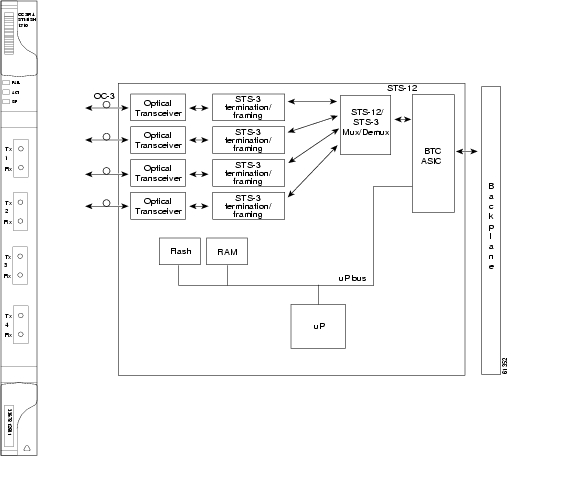
4.2 OC3 IR 4/STM1 SH 1310 Card
Note
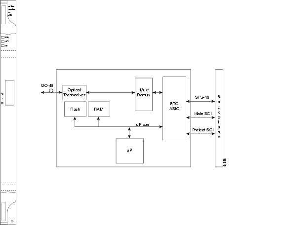
The OC3 IR 4/STM1 SH 1310 card provides four intermediate or short range SONET/SDH OC-3 ports compliant with ITU-T G.707, ITU-T G.957, and Telcordia GR-253-CORE. Each port operates at 155.52 Mbps over a single-mode fiber span. The card supports Virtual Tributary (VT), nonconcatenated (STS-1), or concatenated (STS-1 or STS-3c) payloads. Figure 4-1 shows the OC3 IR 4/STM1 SH 1310 faceplate and a block diagram of the card.
Note
Figure 4-1 OC3 IR 4/STM1 SH 1310 Faceplate and Block Diagram
You can install the OC3 IR 4/STM1 SH 1310 card in Slots 1 to 6 and 12 to 17. The card can be provisioned as part of a path protection or in a linear add/drop multiplexer (ADM) configuration. Each interface features a 1310-nm laser and contains a transmit and receive connector (labeled) on the card faceplate. The card uses SC connectors.
The OC3 IR 4/STM1 SH 1310 card supports 1+1 unidirectional or bidirectional protection switching. You can provision protection on a per port basis.
The OC3 IR 4/STM1 SH 1310 card detects loss of signal (LOS), loss of frame (LOF), loss of pointer (LOP), line-layer alarm indication signal (AIS-L), and line-layer remote defect indication (RDI-L) conditions. Refer to the Cisco ONS 15454 Troubleshooting Guide for a description of these conditions. The card also counts section and line bit interleaved parity (BIP) errors.
To enable automatic protection switching (APS), the OC3 IR 4/STM1 SH 1310 card extracts the K1 and K2 bytes from the SONET overhead to perform appropriate protection switches. The data communication channel/general communication channel (DCC/GCC) bytes are forwarded to the TCC2/TCC2P card, which terminates the DCC/GCC.
4.2.1 OC3 IR 4/STM1 SH 1310 Card-Level Indicators
Table 4-3 describes the three card-level LED indicators on the OC3 IR 4/STM1 SH 1310 card.
4.2.2 OC3 IR 4/STM1 SH 1310 Port-Level Indicators
Eight bicolor LEDs show the status per port. The LEDs are green if the port is available to carry traffic, is provisioned as in-service, and is part of a protection group, in the active mode. You can find the status of the four card ports by using the LCD screen on the ONS 15454 fan-tray assembly. Use the LCD to view the status of any port or card slot; the screen displays the number and severity of alarms for a given port or slot. Refer to the Cisco ONS 15454 Troubleshooting Guide for a complete description of the alarm messages.
4.3 OC3 IR/STM1 SH 1310-8 Card
Note
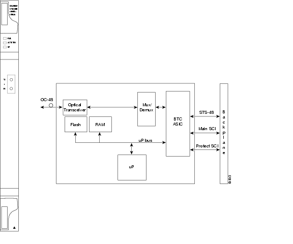
The OC3 IR/STM1 SH 1310-8 card provides eight intermediate or short range SONET/SDH OC-3 ports compliant with ITU-T G.707, ITU-T G.957, and Telcordia GR-253-CORE. Each port operates at 155.52 Mbps over a single-mode fiber span. The card supports VT, nonconcatenated (STS-1), or concatenated (STS-3C) payloads.
Figure 4-2 shows the card faceplate and block diagram.
Figure 4-2 OC3IR/STM1 SH 1310-8 Faceplate and Block Diagram
You can install the OC3 IR/STM1 SH 1310-8 card in Slots 1 to 4 and 14 to 17. The card can be provisioned as part of a path protection or in an ADM configuration. Each interface features a 1310-nm laser and contains a transmit and receive connector (labeled) on the card faceplate. The card uses LC connectors on the faceplate that are angled downward 12.5 degrees.
The OC3 IR/STM1 SH 1310-8 card supports 1+1 unidirectional and bidirectional protection switching. You can provision protection on a per port basis.
The OC3 IR/STM1 SH 1310-8 card detects LOS, LOF, LOP, AIS-L, and RDI-L conditions. Refer to the Cisco ONS 15454 Troubleshooting Guide for a description of these conditions. The card also counts section and line BIP errors.
To enable APS, the OC3 IR/STM1 SH 1310-8 card extracts the K1 and K2 bytes from the SONET overhead to perform appropriate protection switches. The OC3 IR/STM1 SH 1310-8 card supports full DCC/GCC connectivity for remote network management.
4.3.1 OC3 IR/STM1 SH 1310-8 Card-Level Indicators
Table 4-4 describes the three card-level LEDs on the eight-port OC3 IR/STM1 SH 1310-8 card.
4.3.2 OC3 IR/STM1 SH 1310-8 Port-Level Indicators
Eight bicolor LEDs show the status per port. The LEDs show green if the port is available to carry traffic, is provisioned as in-service, is part of a protection group, or is in the active mode. You can also find the status of the eight card ports by using the LCD screen on the ONS 15454 fan-tray assembly. Use the LCD to view the status of any port or card slot; the screen displays the number and severity of alarms for a given port or slot. Refer to the Cisco ONS 15454 Troubleshooting Guide for a complete description of the alarm messages.
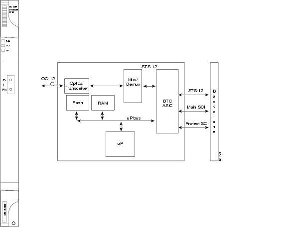
4.4 OC12 IR/STM4 SH 1310 Card
Note
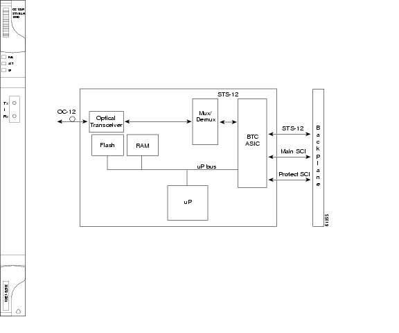
The OC12 IR/STM4 SH 1310 card provides one intermediate or short range SONET OC-12 port compliant with ITU-T G.707, ITU-T G.957, and Telcordia GR-253-CORE. The port operates at 622.08 Mbps over a single-mode fiber span. The card supports VT, nonconcatenated (STS-1), or concatenated (STS-3c, STS-6c, or STS-12c) payloads. Figure 4-3 shows the OC12 IR/STM4 SH 1310 faceplate and a block diagram of the card.
Note
Figure 4-3 OC12 IR/STM4 SH 1310 Faceplate and Block Diagram
You can install the OC12 IR/STM4 SH 1310 card in Slots 1 to 6 and 12 to 17, and provision the card as a drop card or span card in a two-fiber BLSR, path protection, or ADM (linear) configuration.
The OC12 IR/STM4 SH 1310 card interface features a 1310-nm laser and contains a transmit and receive connector (labeled) on the card faceplate. The OC12 IR/STM4 SH 1310 card uses SC optical connections and supports 1+1 unidirectional and bidirectional protection.
The OC12 IR/STM4 SH 1310 detects LOS, LOF, LOP, AIS-L, and RDI-L conditions. Refer to the Cisco ONS 15454 Troubleshooting Guide for a description of these conditions. The card also counts section and line BIT errors.
To enable APS, the OC12 IR/STM4 SH 1310 card extracts the K1 and K2 bytes from the SONET overhead to perform appropriate protection switches. The DCC/GCC bytes are forwarded to the TCC2/TCC2P card, which terminates the DCC/GCC.
4.4.1 OC12 IR/STM4 SH 1310 Card-Level Indicators
Table 4-5 describes the three card-level LEDs on the OC12 IR/STM4 SH 1310 card.
4.4.2 OC12 IR/STM4 SH 1310 Port-Level Indicators
You can find the status of the OC-12 IR/STM4 SH 1310 card port by using the LCD screen on the ONS 15454 fan-tray assembly. Use the LCD to view the status of any port or card slot; the screen displays the number and severity of alarms for a given port or slot. Refer to the Cisco ONS 15454 Troubleshooting Guide for a complete description of the alarm messages.
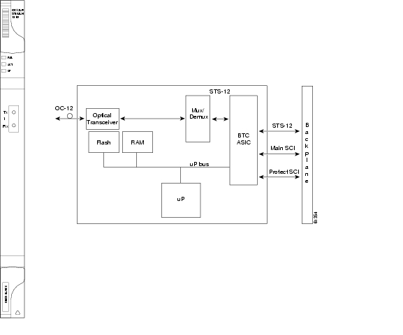
4.5 OC12 LR/STM4 LH 1310 Card
Note
The OC12 LR/STM4 LH 1310 card provides one long-range SONET OC-12 port per card compliant with ITU-T G.707, ITU-T G.957, and Telcordia GR-253-CORE. The port operates at 622.08 Mbps over a single-mode fiber span. The card supports VT, nonconcatenated (STS-1), or concatenated (STS-3c, STS-6c, or STS-12c) payloads. Figure 4-4 shows the OC12 LR/STM4 LH 1310 faceplate and a block diagram of the card.
Note
Figure 4-4 OC12 LR/STM4 LH 1310 Faceplate and Block Diagram
You can install the OC12 LR/STM4 LH 1310 card in Slots 1 to 6 and 12 to 17, and provision the card as a drop card or span card in a two-fiber BLSR, path protection, or ADM (linear) configuration.
The OC12 LR/STM4 LH 1310 card interface features a 1310-nm laser and contains a transmit and receive connector (labeled) on the card faceplate. The card uses SC optical connections and supports 1+1 unidirectional and bidirectional protection.
The OC12 LR/STM4 LH 1310 card detects LOS, LOF, LOP, AIS-L, and RDI-L conditions. Refer to the Cisco ONS 15454 Troubleshooting Guide for a description of these conditions. The card also counts section and line BIT errors.
To enable APS, the OC12 LR/STM4 LH 1310 card extracts the K1 and K2 bytes from the SONET overhead to perform appropriate protection switches. The DCC/GCC bytes are forwarded to the TCC2/TCC2P card, which terminates the DCC/GCC.
4.5.1 OC12 LR/STM4 LH 1310 Card-Level Indicators
Table 4-6 describes the three card-level LEDs on the OC12 LR/STM4 LH 1310 card.
4.5.2 OC12 LR/STM4 LH 1310 Port-Level Indicators
You can find the status of the OC12 LR/STM4 LH 1310 card port by using the LCD screen on the ONS 15454 fan-tray assembly. Use the LCD to quickly view the status of any port or card slot; the screen displays the number and severity of alarms for a given port or slot.
4.6 OC12 LR/STM4 LH 1550 Card
Note
The OC12 LR/STM4 LH 1550 card provides one long-range SONET/SDH OC-12 port compliant with ITU-T G.707, ITU-T G.957, and Telcordia GR-253-CORE. The port operates at 622.08 Mbps over a single-mode fiber span. The card supports VT, nonconcatenated (STS-1), or concatenated (STS-3c, STS-6c, or STS-12c) payloads. Figure 4-5 shows the OC12 LR/STM4 LH 1550 faceplate and a block diagram of the card.
Note
Figure 4-5 OC12 LR/STM4 LH 1550 Faceplate and Block Diagram
You can install the OC12 LR/STM4 LH 1550 card in Slots 1 to 4 and 14 to 17. The OC12 LR/STM4 LH 1550 can be provisioned as part of a two-fiber BLSR, path protection, or linear ADM.
The OC12 LR/STM4 LH 1550 uses long-reach optics centered at 1550 nm and contains a transmit and receive connector (labeled) on the card faceplate. The OC12 LR/STM4 LH 1550 uses SC optical connections and supports 1+1 bidirectional or unidirectional protection switching.
The OC12 LR/STM4 LH 1550 detects LOS, LOF, LOP, AIS-L, and RDI-L conditions. The card also counts section and line BIT errors.
4.6.1 OC12 LR/STM4 LH 1550 Card-Level Indicators
Table 4-7 describes the three card-level LEDs on the OC12 LR/STM4 LH 1550 card.
4.6.2 OC12 LR/STM4 LH 1550 Port-Level Indicators
You can find the status of the OC12 LR/STM4 LH 1550 card port by using the LCD screen on the ONS 15454 fan-tray assembly. Use the LCD to view the status of any port or card slot; the screen displays the number and severity of alarms for a given port or slot.
4.7 OC12 IR/STM4 SH 1310-4 Card
Note
The OC12 IR/STM4 SH 1310-4 card provides four intermediate or short range SONET/SDH OC-12/STM-4 ports compliant with the ITU-T G.707, ITU-T G.957, and Telcordia GR-253-CORE. Each port operates at 622.08 Mbps over a single-mode fiber span. The card supports VT, nonconcatenated (STS-1), or concatenated (STS-1, STS-3c, STS-6c, or STS-12c) payloads.
Figure 4-6 shows the OC12 IR/STM4 SH 1310-4 faceplate and a block diagram of the card.
Figure 4-6 OC12 IR/STM4 SH 1310-4 Faceplate and Block Diagram
You can install the OC12 IR/STM4 SH 1310-4 card in Slots 1 to 4 and 14 to 17. Each interface features a 1310-nm laser and contains a transmit and receive connector (labeled) on the card faceplate. The card uses SC connectors.
The OC12 IR/STM4 SH 1310-4 card supports 1+1 unidirectional and bidirectional protection switching. You can provision protection on a per port basis.
The OC12 IR/STM4 SH 1310-4 card detects LOS, LOF, LOP, MS-AIS, and MS-FERF conditions. Refer to the Cisco ONS 15454 Troubleshooting Guide for a description of these conditions. The card also counts section and line BIP errors.
To enable BLSR, the OC12 IR/STM4 SH 1310-4 card extracts the K1 and K2 bytes from the SONET overhead and processes them to switch accordingly. The DCC/GCC bytes are forwarded to the TCC2/TCC2P card, which terminates the DCC/GCC.
Note
4.7.1 OC12 IR/STM4 SH 1310-4 Card-Level Indicators
Table 4-8 describes the three card-level LEDs on the OC12 IR/STM4 SH 1310-4 card.
4.7.2 OC12 IR/STM4 SH 1310-4 Port-Level Indicators
You can find the status of the four card ports by using the LCD screen on the ONS 15454 fan-tray assembly. Use the LCD to view the status of any port or card slot; the screen displays the number and severity of alarms for a given port or slot.
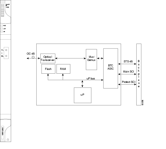
4.8 OC48 IR 1310 Card
Note
Note
The OC48 IR 1310 card provides one intermediate-range, SONET OC-48 port per card, compliant with Telcordia GR-253-CORE. Each port operates at 2.49 Gbps over a single-mode fiber span. The card supports VT, nonconcatenated (STS-1), or concatenated (STS-3c, STS-6c, STS-12c, or STS-48c) payloads.
Figure 4-7 shows the OC48 IR 1310 faceplate and a block diagram of the card.
Figure 4-7 OC48 IR 1310 Faceplate and Block Diagram
You can install the OC48 IR 1310 card in Slots 5, 6, 12, and 13, and provision the card as a drop or span card in a two-fiber or four-fiber BLSR, path protection, or in an ADM (linear) configuration.
The OC-48 port features a 1310-nm laser and contains a transmit and receive connector (labeled) on the card faceplate. The OC48 IR 1310 uses SC connectors. The card supports 1+1 unidirectional and bidirectional protection switching.
The OC48 IR 1310 detects LOS, LOF, LOP, AIS-L, and RDI-L conditions. The card also counts section and line BIP errors.
4.8.1 OC48 IR 1310 Card-Level Indicators
Table 4-9 describes the three card-level LEDs on the OC48 IR 1310 card.
4.8.2 OC48 IR 1310 Port-Level Indicators
You can find the status of the OC48 IR 1310 card port by using the LCD screen on the ONS 15454 fan-tray assembly. Use the LCD to view the status of any port or card slot; the screen displays the number and severity of alarms for a given port or slot.
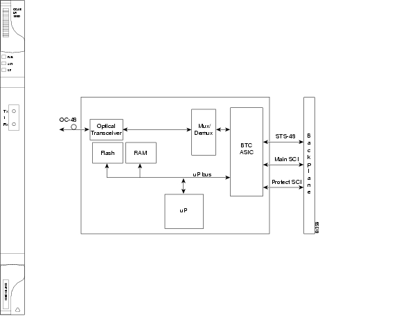
4.9 OC48 LR 1550 Card
Note
Note
The OC48 LR 1550 card provides one long-range, SONET OC-48 port per card, compliant with Telcordia GR-253-CORE. Each port operates at 2.49 Gbps over a single-mode fiber span. The card supports VT, nonconcatenated (STS-1), or concatenated (STS-3c, STS-6c, STS-12c, or STS-48c) payloads.
Figure 4-8 shows the OC48 LR 1550 faceplate and a block diagram of the card.
Figure 4-8 OC48 LR 1550 Faceplate and Block Diagram
You can install OC48 LR 1550 cards in Slots 5, 6, 12, and 13 and provision the card as a drop or span card in a two-fiber or four-fiber BLSR, path protection, or ADM (linear) configuration.
The OC48 LR 1550 port features a 1550-nm laser and contains a transmit and receive connector (labeled) on the card faceplate. The card uses SC connectors, and it supports 1+1 unidirectional and bidirectional protection switching.
The OC48 LR 1550 detects LOS, LOF, LOP, AIS-L, and RDI-L conditions. The card also counts section and line BIP errors.
4.9.1 OC48 LR 1550 Card-Level Indicators
Table 4-10 describes the three card-level LEDs on the OC48 LR 1550 card.
4.9.2 OC48 LR 1550 Port-Level Indicators
You can find the status of the OC48 LR 1550 card port by using the LCD screen on the ONS 15454 fan-tray assembly. Use the LCD to view the status of any port or card slot; the screen displays the number and severity of alarms for a given port or slot.
4.10 OC48 IR/STM16 SH AS 1310 Card
Note
The OC48 IR/STM16 SH AS 1310 card provides one intermediate-range SONET/SDH OC-48 port compliant with ITU-T G.707, ITU-T G.957, and Telcordia GR-253-CORE. The port operates at 2.49 Gbps over a single-mode fiber span. The card supports VT, nonconcatenated (STS-1), or concatenated (STS-3c, STS-6c, STS-12c, or STS-48c) payloads. Figure 4-9 shows the OC48 IR/STM16 SH AS 1310 faceplate and a block diagram of the card.
Figure 4-9 OC48 IR/STM16 SH AS 1310 Faceplate and Block Diagram
You can install the OC48 IR/STM16 SH AS 1310 card in Slots 1 to 6 and 12 to 17 and provision the card as a drop or span card in a two-fiber or four-fiber BLSR, path protection, or ADM (linear) configuration.
The OC-48 port features a 1310-nm laser and contains a transmit and receive connector (labeled) on the card faceplate. The OC48 IR/STM16 SH AS 1310 uses SC connectors. The card supports 1+1 unidirectional and bidirectional protection switching.
The OC48 IR/STM16 SH AS 1310 detects LOS, LOF, LOP, AIS-L, and RDI-L conditions. The card also counts section and line BIP errors.
4.10.1 OC48 IR/STM16 SH AS 1310 Card-Level Indicators
Table 4-11 lists the three card-level LEDs on the OC48 IR/STM16 SH AS 1310 card.
4.10.2 OC48 IR/STM16 SH AS 1310 Port-Level Indicators
You can find the status of the OC48 IR/STM16 SH AS 1310 card port by using the LCD screen on the ONS 15454 fan-tray assembly. Use the LCD to view the status of any port or card slot; the screen displays the number and severity of alarms for a given port or slot.
4.11 OC48 LR/STM16 LH AS 1550 Card
Note
The OC48 LR/STM16 LH AS 1550 card provides one long-range SONET/SDH OC-48 port compliant with ITU-T G.707, ITU-T G.957, and Telcordia GR-253-CORE. Each port operates at 2.49 Gbps over a single-mode fiber span. The card supports VT, nonconcatenated (STS-1), or concatenated (STS-3c, STS-6c, STS-12c, or STS-48c) payloads.
Figure 4-10 shows a block diagram and the faceplate of the OC48 LR/STM16 LH AS 1550 card.
Figure 4-10 OC48 LR/STM16 LH AS 1550 Faceplate and Block Diagram
You can install OC48 LR/STM16 LH AS 1550 cards in Slots 1 to 6 and 12 to 17 and provision the card as a drop or span card in a two-fiber or four-fiber BLSR, path protection, or ADM (linear) configuration.
The OC48 LR/STM16 LH AS 1550 port features a 1550-nm laser and contains a transmit and receive connector (labeled) on the card faceplate. The card uses SC connectors, and it supports 1+1 unidirectional and bidirectional protection switching.
The OC48 LR/STM16 LH AS 1550 detects LOS, LOF, LOP, AIS-L, and RDI-L conditions. The card also counts section and line BIP errors.
4.11.1 OC48 LR/STM16 LH AS 1550 Card-Level Indicators
Table 4-12 describes the three card-level LEDs on the OC48 LR/STM16 LH AS 1550 card.
4.11.2 OC48 LR/STM16 LH AS 1550 Port-Level Indicators
You can find the status of the OC48 LR/STM16 LH AS 1550 card port by using the LCD screen on the ONS 15454 fan-tray assembly. Use the LCD to view the status of any port or card slot; the screen displays the number and severity of alarms for a given port or slot.
4.12 OC48 ELR/STM16 EH 100 GHz Cards
Note
Thirty-seven distinct OC48 ELR/STM16 EH 100 GHz cards provide the ONS 15454 DWDM channel plan. Each OC48 ELR/STM16 EH 100 GHz card has one SONET OC-48/SDH STM-16 port that complies with Telcordia GR-253-CORE, ITU-T G.692, and ITU-T G.958.
The port operates at 2.49 Gbps over a single-mode fiber span. The card carries VT, concatenated (STS-1), and nonconcatenated (STS-1, STS-3c, STS-6c, STS-12c, or STS-48c) payloads.
Figure 4-11 shows the OC48 ELR/STM16 EH 100 GHz faceplate and a block diagram of the card.
Figure 4-11 OC48 ELR/STM16 EH 100 GHz Faceplate and Block Diagram
Nineteen of the cards operate in the blue band with spacing of 100 GHz on the ITU grid (1528.77 nm, 1530.33 nm, 1531.12 nm, 1531.90 nm, 1532.68 nm, 1533.47 nm, 1534.25 nm, 1535.04 nm, 1535.82 nm, 1536.61 nm, 1538.19 nm, 1538.98 nm, 1539.77 nm, 1540.56 nm, 1541.35 nm, 1542.14 nm, 1542.94 nm, 1543.73 nm, and 1544.53 nm). ITU spacing conforms to ITU-T G.692 and Telcordia GR-2918-CORE, Issue 2.
The other eighteen cards operate in the red band with spacing of 100 GHz on the ITU grid (1546.12 nm, 1546.92 nm, 1547.72 nm, 1548.51 nm,1549.32 nm, 1550.12 nm, 1550.92 nm, 1551.72 nm, 1552.52 nm, 1554.13 nm, 1554.94 nm, 1555.75 nm, 1556.55 nm, 1557.36 nm, 1558.17 nm, 1558.98 nm, 1559.79 nm, and 1560.61 nm). These cards are also designed to interoperate with the Cisco ONS 15216 DWDM solution.
You can install the OC48 ELR/STM16 EH 100 GHz cards in Slots 5, 6, 12, and 13 and provision the card as a drop or span card in a two-fiber or four-fiber BLSR, path protection, or ADM (linear) configuration. Each OC48 ELR/STM16 EH 100 GHz card uses extended long-reach optics operating individually within the ITU-T 100-GHz grid. The OC-48 DWDM cards are intended to be used in applications with long unregenerated spans of up to 300 km (186 miles) (with mid-span amplification). These transmission distances are achieved through the use of inexpensive optical amplifiers (flat gain amplifiers) such as Cisco ONS 15216 erbium-doped fiber amplifiers (EDFAs).
Maximum system reach in filterless applications is 26 dB without the use of optical amplifiers or regenerators. However, system reach also depends on the condition of the facilities, the number of splices and connectors, and other performance-affecting factors. When used in combination with ONS 15216 100-GHz filters, the link budget is reduced by the insertion loss of the filters plus an additional 2-dB power penalty. The wavelength stability of the OC48 ELR/STM16 EH 100 GHz cards is +/- 0.12 nm for the life of the product and over the full range of operating temperatures. Each interface contains a transmitter and receiver.
The OC48 ELR/STM16 EH 100 GHz cards detect LOS, LOF, LOP, and AIS-L conditions. The cards also count section and line BIP errors.
4.12.1 OC48 ELR 100 GHz Card-Level Indicators
Table 4-13 lists the three card-level LEDs on the OC48 ELR/STM16 EH 100 GHz cards.
4.12.2 OC48 ELR 100 GHz Port-Level Indicators
You can find the status of the OC48 ELR/STM16 EH 100 GHz card ports by using the LCD screen on the ONS 15454 fan-tray assembly. Use the LCD to quickly view the status of any port or card slot; the screen displays the number and severity of alarms for a given port or slot.
4.13 OC48 ELR 200 GHz Cards
Note
Eighteen distinct OC48 ELR 200 GHz cards provide the ONS 15454 DWDM channel plan. Each OC48 ELR 200 GHz card provides one SONET OC-48 port that is compliant with Telcordia GR-253-CORE. The port operates at 2.49 Gbps over a single-mode fiber span. The card carries VT, concatenated (STS-1), or nonconcatenated (STS-3c, STS-6c, STS-12c, or STS-48c) payloads.
Figure 4-12 shows the OC48 ELR 200 GHz faceplate and a block diagram of the card.
Figure 4-12 OC48 ELR 200 GHz Faceplate and Block Diagram
Nine of the cards operate in the blue band with spacing of 200 GHz on the ITU grid (1530.33 nm, 1531.90 nm, 1533.47 nm, 1535.04 nm, 1536.61 nm, 1538.19 nm, 1539.77 nm, 1541.35 nm, and 1542.94 nm).
The other nine cards operate in the red band with spacing of 200 GHz on the ITU grid
(1547.72 nm, 1549.32 nm, 1550.92 nm, 1552.52 nm, 1554.13 nm, 1555.75 nm, 1557.36 nm, 1558.98 nm, and 1560.61 nm). These cards are also designed to interoperate with the Cisco ONS 15216 DWDM solution.You can install the OC48 ELR 200 GHz cards in Slots 5, 6, 12, and 13, and provision the card as a drop or span card in a two-fiber or four-fiber BLSR, path protection, or ADM (linear) configuration. Each OC48 ELR 200 GHz card uses extended long-reach optics operating individually within the ITU-T 200-GHz grid. The OC48 ELR 200 GHz cards are intended to be used in applications with long unregenerated spans of up to 200 km (124 miles) (with mid-span amplification). These transmission distances are achieved through the use of inexpensive optical amplifiers (flat gain amplifiers) such as EDFAs. Using collocated amplification, distances up to 200 km (124 miles) can be achieved for a single channel, 160 km (99 miles) for 8 channels.
Maximum system reach in filterless applications is 24 dB or approximately 80 km (50 miles) without the use of optical amplifiers or regenerators. However, system reach also depends on the condition of the facilities, the number of splices and connectors, and other performance-affecting factors. The OC48 ELR DWDM cards feature wavelength stability of +/-0.25 nm. Each interface contains a transmitter and receiver.
The OC48 ELR 200 GHz cards support extended long-reach applications in conjunction with optical amplification. Using electro-absorption technology, the OC48 DWDM cards provide a solution at the lower extended long-reach distances.
The OC48 ELR 200 GHz interface features a 1550-nm laser and contains a transmit and receive connector (labeled) on the card faceplate. The card uses SC connectors and supports 1+1 unidirectional and bidirectional protection switching.
The OC48 ELR 200 GHz cards detect LOS, LOF, LOP, AIS-L, and RDI-L conditions. The cards also count section and line BIP errors. To enable APS, the OC48 ELR 200 GHz cards extract the K1 and K2 bytes from the SONET overhead. The DCC bytes are forwarded to the TCC2/TCC2P card; the TCC2/TCC2P terminates the DCC/GCC.
4.13.1 OC48 ELR 200 GHz Card-Level Indicators
Table 4-14 describes the three card-level LEDs on the OC48 ELR 200 GHz cards.
4.13.2 OC48 ELR 200 GHz Port-Level Indicators
You can find the status of the OC48 ELR 200 GHz card ports by using the LCD screen on the ONS 15454 fan-tray assembly. Use the LCD to quickly view the status of any port or card slot; the screen displays the number and severity of alarms for a given port or slot.
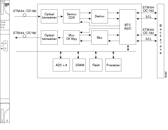
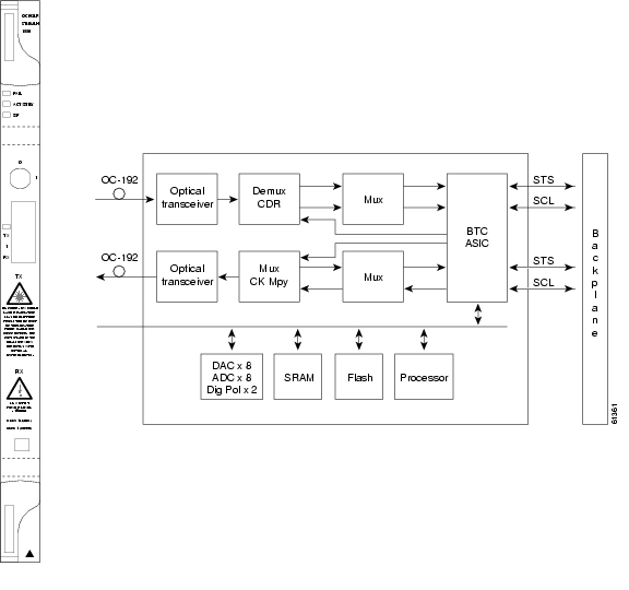
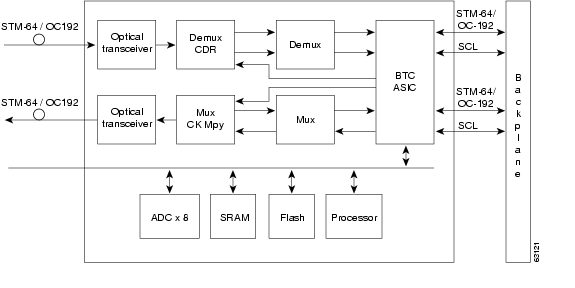
4.14 OC192 SR/STM64 IO 1310 Card
Note
The OC192 SR/STM64 IO 1310 card provides one intra-office haul SONET/SDH OC-192 port in the 1310-nm wavelength range, compliant with ITU-T G.707, ITU-T G.691, ITU-T G.957, and Telcordia GR-253-CORE. The port operates at 9.95328 Gbps over unamplified distances up to 2 km (1.24 miles). The card supports VT, nonconcatenated (STS-1), or concatenated payloads.
Figure 4-13 shows the OC192 SR/STM64 IO 1310 faceplate and block diagram.
Figure 4-13 OC192 SR/STM64 IO 1310 Faceplate and Block Diagram
You can install OC192 SR/STM64 IO 1310 cards in Slot 5, 6, 12, or 13. You can provision this card as part of a BLSR, a path protection, a linear configuration, or as a regenerator for longer span reaches.
The OC192 SR/STM64 IO 1310 port features a 1310-nm laser and contains a transmit and receive connector (labeled) on the card faceplate. The card uses a dual SC connector for optical cable termination. The card supports 1+1 unidirectional and bidirectional facility protection. It also supports 1:1 protection in four-fiber BLSR applications where both span switching and ring switching might occur.
The OC192 SR/STM64 IO 1310 card detects SF, LOS, or LOF conditions on the optical facility. Refer to the Cisco ONS 15454 Troubleshooting Guide for a description of these conditions. The card also counts section and line BIP errors from B1 and B2 byte registers in the section and line overhead.
4.14.1 OC192 SR/STM64 IO 1310 Card-Level Indicators
Table 4-15 describes the three card-level LEDs on the OC192 SR/STM64 IO 1310 card.
4.14.2 OC192 SR/STM64 IO 1310 Port-Level Indicators
You can find the status of the OC192 SR/STM64 IO 1310 card ports by using the LCD screen on the ONS 15454 fan-tray assembly. Use the LCD to view the status of any port or card slot; the screen displays the number and severity of alarms for a given port or slot. Refer to the Cisco ONS 15454 Troubleshooting Guide for a complete description of the alarm messages.
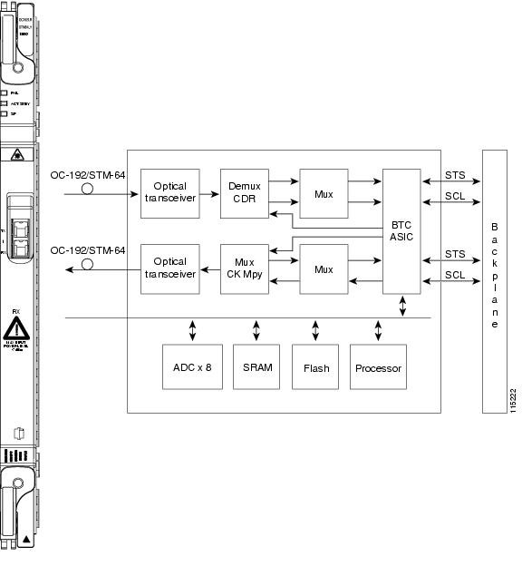
4.15 OC192 IR/STM64 SH 1550 Card
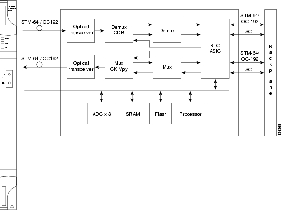
Note
The OC192 IR/STM64 SH 1550 card provides one intermediate reach SONET/SDH OC-192 port in the 1550-nm wavelength range, compliant with ITU-T G.707,ITU-T G.691, ITU-T G.957, and Telcordia GR-253-CORE. The port operates at 9.95328 Gbps over unamplified distances up to 40 km (25 miles) with SMF-28 fiber limited by loss and/or dispersion. The card supports VT, nonconcatenated (STS-1), or concatenated payloads.
Figure 4-14 shows the OC192 IR/STM64 SH 1550 faceplate and block diagram.
Figure 4-14 OC192 IR/STM64 SH 1550 Faceplate and Block Diagram
Note
You can install OC192 IR/STM64 SH 1550 cards in Slot 5, 6, 12, or 13. You can provision this card as part of a BLSR, path protection, or linear configuration, or also as a regenerator for longer span reaches.
The OC192 IR/STM64 SH 1550 port features a 1550-nm laser and contains a transmit and receive connector (labeled) on the card faceplate. The card uses a dual SC connector for optical cable termination. The card supports 1+1 unidirectional and bidirectional facility protection. It also supports 1:1 protection in four-fiber BLSR applications where both span switching and ring switching might occur.
The OC192 IR/STM64 SH 1550 card detects SF, LOS, or LOF conditions on the optical facility. Refer to the Cisco ONS 15454 Troubleshooting Guide for a description of these conditions. The card also counts section and line BIP errors from B1 and B2 byte registers in the section and line overhead.
4.15.1 OC192 IR/STM64 SH 1550 Card-Level Indicators
Table 4-16 describes the three card-level LEDs on the OC192 IR/STM64 SH 1550 card.
4.15.2 OC192 IR/STM64 SH 1550 Port-Level Indicators
You can find the status of the OC192 IR/STM64 SH 1550 card ports by using the LCD screen on the ONS 15454 fan-tray assembly. Use the LCD to view the status of any port or card slot; the screen displays the number and severity of alarms for a given port or slot. Refer to the Cisco ONS 15454 Troubleshooting Guide for a complete description of the alarm messages.
4.16 OC192 LR/STM64 LH 1550 Card
Note
Note
The OC192 LR/STM64 LH 1550 card provides one long-range SONET/SDH OC-192 port compliant with ITU-T G.707, ITU-T G.691, ITU-T G.957, and Telcordia GR-253-CORE (except minimum and maximum transmit power, and minimum receive power). The card port operates at 9.95328 Gbps over unamplified distances up to 80 km (50 miles) with different types of fiber such as C-SMF or dispersion compensated fiber limited by loss and/or dispersion. The card supports VT, nonconcatenated (STS-1), or concatenated payloads.
There are two versions of the OC192 LR/STM64 LH 1550. The earliest version has the product ID 15454-OC192LR1550, and the latest card's product ID is 15454-OC192-LR2. These cards have slight specification differences that are noted throughout this description.
Note
Figure 4-15 shows the OC192 LR/STM64 LH 1550 (15454-OC192LR1550) faceplate and a block diagram of the card.
Figure 4-15 OC192 LR/STM64 LH 1550 (15454-OC192LR1550) Faceplate and Block Diagram
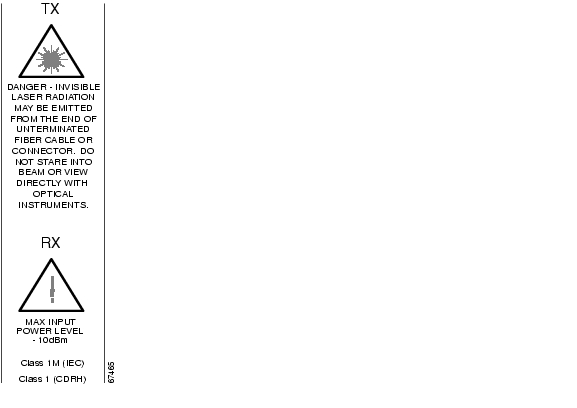
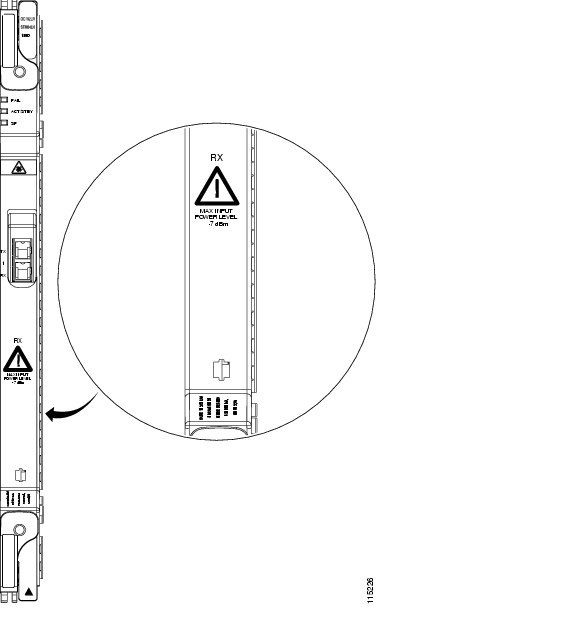
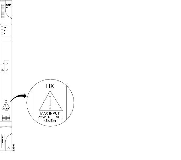
Figure 4-16 shows an enlarged view of the faceplate warning for 15454-OC192-LR2.
Figure 4-16 Enlarged Section of the OC192 LR/STM64 LH 1550 (15454-OC192LR1550) Faceplate
Figure 4-17 shows the OC192 LR/STM64 LH 1550 (15454-OC192-LR2) faceplate and a block diagram of the card.
Figure 4-17 OC192 LR/STM64 LH 1550 (15454-OC192-LR2) Faceplate and Block Diagram
Figure 4-18 shows an enlarged view of the faceplate warning on 15454-OC192LR1550.
Figure 4-18 Enlarged Section of the OC192 LR/STM64 LH 1550 (15454-OC192-LR2)Faceplate
Caution
You can install OC192 LR/STM64 LH 1550 cards in Slots 5, 6, 12, and 13 and provision the card as a drop or span card in a two-fiber or four-fiber BLSR, path protection, ADM (linear) configuration, or as a regenerator for longer span reaches.
The card port features a 1550-nm laser and contains a transmit and receive connector (labeled) on the card faceplate.The card uses a dual SC connector for optical cable termination. The card supports 1+1 unidirectional and bidirectional facility protection. It also supports 1:1 protection in four-fiber BLSR applications where both span switching and ring switching might occur.
The OC192 LR/STM64 LH 1550 card detects SF, LOS, or LOF conditions on the optical facility. The card also counts section and line BIT errors from B1 and B2 byte registers in the section and line overhead.
4.16.1 OC192 LR/STM64 LH 1550 Card-Level Indicators
Table 4-17 describes the three card-level LEDs on the OC192 LR/STM64 LH 1550 card.
4.16.2 OC192 LR/STM64 LH 1550 Port-Level Indicators
You can find the status of the OC192 LR/STM64 LH 1550 card port by using the LCD screen on the ONS 15454 fan-tray assembly. Use the LCD to view the status of the port or card slot; the screen displays the number and severity of alarms for a given port or slot.
Note
4.17 OC192 LR/STM64 LH ITU 15xx.xx Card
Note
Sixteen distinct OC-192/STM-64 ITU 100 GHz DWDM cards comprise the ONS 15454 DWDM channel plan. Each OC192 LR/STM64 LH ITU 15xx.xx card provides one long-reach STM-64/OC-192 port per card, compliant with ITU-T G.707, ITU-T G.957, and Telcordia GR-253-CORE (except minimum and maximum transmit power, and minimum receive power). The port operates at 9.95328 Gbps over unamplified distances up to 60 km (37 miles) with different types of fiber such as C-SMF or dispersion compensated fiber limited by loss and/or dispersion.
Note
The card supports VT, nonconcatenated (STS-1), or concatenated payloads. Figure 4-19 shows the OC192 LR/STM64 LH ITU 15xx.xx faceplate.
Figure 4-19 OC192 LR/STM64 LH ITU 15xx.xx Faceplate
Figure 4-20 shows a block diagram of the OC192 LR/STM64 LH ITU 15xx.xx card.
Figure 4-20 OC192 LR/STM64 LH ITU 15xx.xx Block Diagram
Note
Eight of the cards operate in the blue band with a spacing of 100 GHz in the ITU grid (1534.25 nm, 1535.04 nm, 1535.82 nm, 1536.61 nm, 1538.19 nm, 1538.98 nm, 1539.77 nm, and 1540.56 nm). The other eight cards operate in the red band with a spacing of 100 GHz in the ITU grid (1550.12 nm, 1550.92 nm, 1551.72 nm, 1552.52 nm, 1554.13 nm, 1554.94 nm, 1555.75 nm, and 1556.55 nm).
You can install OC192 LR/STM64 LH ITU 15xx.xx cards in Slot 5, 6, 12, or 13. You can provision this card as part of an BLSR, path protection, or linear configuration or also as a regenerator for longer span reaches.
The OC192 LR/STM64 LH ITU 15xx.xx port features a laser on a specific wavelength in the 1550-nm range and contains a transmit and receive connector (labeled) on the card faceplate. The card uses a dual SC connector for optical cable termination. The card supports 1+1 unidirectional and bidirectional facility protection. It also supports 1:1 protection in four-fiber BLSR applications where both span switching and ring switching might occur.
The OC192 LR/STM64 LH ITU 15xx.xx card detects SF, LOS, or LOF conditions on the optical facility. Refer to the Cisco ONS 15454 Troubleshooting Guide for a description of these conditions. The card also counts section and line BIP errors from B1 and B2 byte registers in the section and line overhead.
4.17.1 OC192 LR/STM64 LH ITU 15xx.xx Card-Level Indicators
Table 4-18 describes the three card-level LEDs on the OC192 LR/STM64 LH ITU 15xx.xx card.
4.17.2 OC192 LR/STM64 LH ITU 15xx.xx Port-Level Indicators
You can find the status of the OC192 LR/STM64 LH ITU 15xx.xx card ports by using the LCD screen on the ONS 15454 fan-tray assembly. Use the LCD to view the status of any port or card slot; the screen displays the number and severity of alarms for a given port or slot. Refer to the Cisco ONS 15454 Troubleshooting Guide for a complete description of the alarm messages.
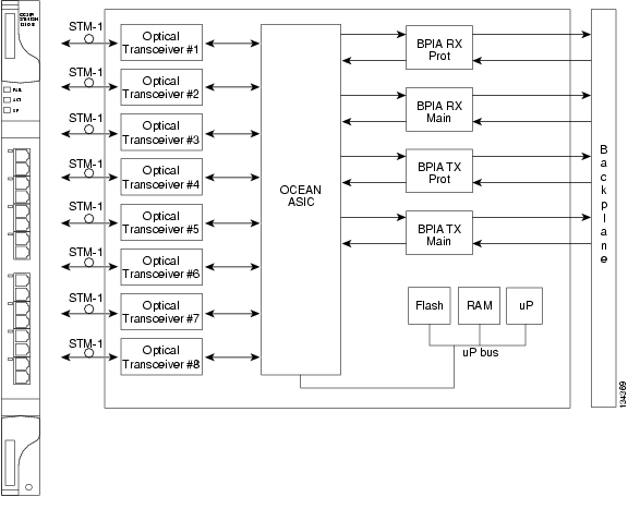
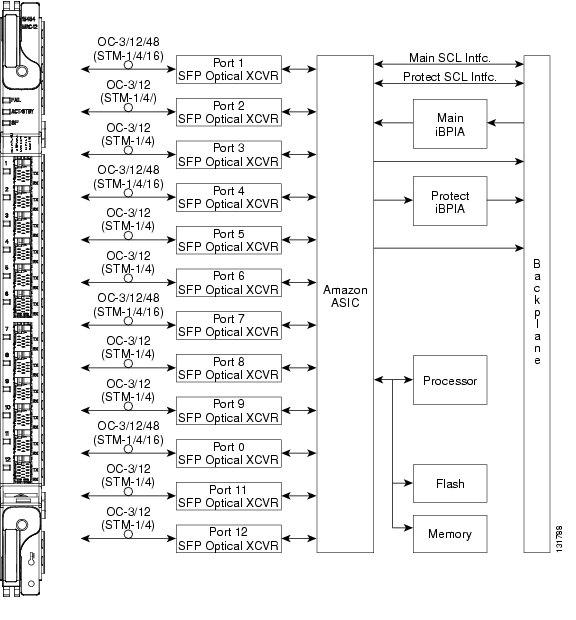
4.18 15454_MRC-12 Multirate Card
Note
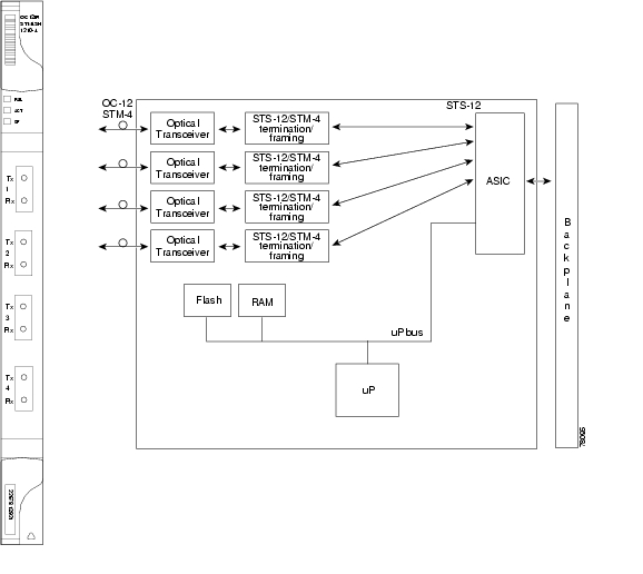
The 15454_MRC-12 multirate card provides up to twelve OC-3/STM-1 ports, twelve OC-12/STM-4 ports, or four OC-48/STM-16 ports using small form-factor pluggables (SFPs), in any combination of line rates. All ports are Telcordia GR-253 compliant. The SFP optics can use SR, IR, LR, coarse wavelength division multiplexing (CWDM), and DWDM SFPs to support unrepeated spans. See the "Optical Card SFPs and XFPs" section for more information about SFPs.
The ports operate at up to 2488.320 Mbps over a single-mode fiber. The 15454_MRC-12 card has twelve physical connector adapters with two fibers per connector adapter (Tx and Rx). The card supports VT payloads, STS-1 payloads, and concatenated payloads at STS-3c, STS-6c, STS-9c, STS-12c, STS-18c, STS-24c, STS-36c, or STS-48c signal levels. It is fully interoperable with the ONS 15454 G-Series Ethernet cards.
The 15454_MRC-12 port contains a transmit and receive connector (labeled) on the card faceplate. The card supports 1+1 unidirectional and bidirectional facility protection. It also supports 1+1 protection in four-fiber BLSR applications where both span switching and ring switching might occur. You can provision this card as part of an BLSR, path protection, or 1+1 linear configuration.
Note
Figure 4-21 shows the 15454_MRC-12 faceplate and block diagram.
Figure 4-21 15454_MRC-12 Card Faceplate and Block Diagram
4.18.1 Slot Compatibility by Cross-Connect Card
You can install 15454_MRC-12 cards in Slots 1 through 6 and 12 through 17 with an XCVT, XC10G, or XC-VXC-10G.
Note
The maximum bandwidth of the 15454_MRC-12 card is determined by the cross-connect card, as shown in Table 4-19.
4.18.2 Ports and Line Rates
Each port on the 15454_MRC-12 card can be configured as OC-3/STM-1, OC-12/STM-4, or OC-48/STM-16, depending on the available bandwidth and existing provisioned ports. Based on the cross-connect card and slot limitations shown in Table 4-19, the following rules apply for various synchronous transport signal (STS) available bandwidths. ( Table 4-20 shows the same information in tabular format.)
•
–
–
•
–
–
–
–
–
–
•
–
–
–
–
–
–
–
–
–
–
–
Table 4-20 shows the 15454_MRC-12 port availability and line rate for each port, based on total available bandwidth. To use the table, go to the rows for the bandwidth that you have available, as determined in Table 4-19. Each row indicates what line rate can be provisioned for each port (identified in the MCR-12 Port Number row). The Ports Used column shows the total number of ports that can be used with each bandwidth scheme.
Table 4-20 Line Rate Configurations Per 15454_MRC-12 Port, Based on Available Bandwidth
OC-3
OC-12
OC-48OC-3
OC-12OC-3
OC-12OC-3
OC-12
OC-48OC-3
OC-12OC-3
OC-12OC-3
OC-12
OC-48OC-3
OC-12OC-3
OC-12OC-3
OC-12
OC-48OC-3
OC-12OC-3
OC-12—
—
STS-12 Available Bandwidth
12
—
—
—
—
—
—
—
—
—
—
—
1
12
3
—
—
3
—
—
3
—
—
3
—
—
4
12
STS-48 Available Bandwidth
3
3
3
3
3
3
3
3
3
3
3
3
12
36
3
—
—
12
3
3
3
3
3
3
3
3
10
39
3
—
—
12
—
—
12
—
3
3
3
3
7
39
3
—
—
12
—
—
12
—
—
12
—
—
4
39
12
3
3
3
3
3
3
3
3
3
3
3
12
45
12
—
—
12
3
3
3
3
3
3
3
3
10
48
12
—
—
12
—
—
12
—
3
3
3
3
7
48
12
—
—
12
—
—
12
—
—
12
—
—
4
48
12
3
3
3
—
—
12
—
3
3
3
3
9
45
12
3
3
3
3
3
3
3
—
12
—
—
9
45
3
3
3
3
3
3
3
3
—
12
—
—
9
36
3
3
3
3
—
—
12
—
—
12
—
—
6
36
48
—
—
—
—
—
—
—
—
—
—
—
1
48
STS-192 Available Bandwidth
(when installing additional SFPs from the top port to the bottom port)1
48
3
3
3
3
3
3
3
3
3
3
3
12
81
48
12
12
12
3
3
3
3
3
3
3
3
12
108
48
12
12
12
12
12
12
12
3
3
3
3
12
144
48
12
12
12
12
12
12
12
12
12
12
12
12
180
48
3
3
3
12
12
12
12
12
12
12
12
12
153
48
3
3
3
3
3
3
3
12
12
12
12
12
117
48
—
—
48
3
3
3
3
3
3
3
3
10
120
48
—
—
48
12
12
12
12
3
3
3
3
10
156
48
—
—
48
12
12
12
12
12
12
12
12
10
192
48
—
—
48
—
—
48
—
3
3
3
3
7
156
48
—
—
48
—
—
48
—
12
12
12
12
7
192
48
—
—
48
—
—
48
—
—
48
—
—
4
192
STS-192 Available Bandwidth (when installing additional SFPs from the bottom port to the top port) 1
3
3
3
3
3
3
3
3
—
48
—
—
9
72
3
3
3
3
12
12
12
12
—
48
—
—
9
108
3
12
12
12
12
12
12
12
—
48
—
—
9
135
12
12
12
12
12
12
12
12
—
48
—
—
9
144
12
12
12
12
3
3
3
3
—
48
—
—
9
108
12
3
3
3
3
3
3
3
—
48
—
—
9
81
3
3
3
3
—
—
48
—
—
48
—
—
6
108
3
12
12
12
—
—
48
—
—
48
—
—
6
135
12
12
12
12
—
—
48
—
—
48
—
—
6
144
12
3
3
3
—
—
48
—
—
48
—
—
6
117
3
—
—
48
—
—
48
—
—
48
—
—
4
147
12
—
—
48
—
—
48
—
—
48
—
—
4
156
1 If the MRC-12 card is initially populated with OC-3/12 on all its 12 ports, you can later add OC-48 SFPs on that card from top port to bottom port or from bottom port to top port. The maximum available bandwidth usage is different for these two cases.
4.18.3 15454_MRC-12 Card-Level Indicators
Table 4-21 describes the three card-level LEDs on the 15454_MRC-12 card.
4.18.4 15454_MRC-12 Port-Level Indicators
Each port has a Tx and Rx indicator. The Tx LED flashes green if the port is transmitting a signal, and the Rx LED flashes if the port is receiving a signal.
You can also find the status of the 15454_MRC-12 card ports by using the LCD screen on the ONS 15454 fan-tray assembly. Use the LCD to view the status of any port or card slot; the screen displays the number and severity of alarms for a given port or slot. Refer to the Cisco ONS 15454 Troubleshooting Guide for a complete description of the alarm messages.
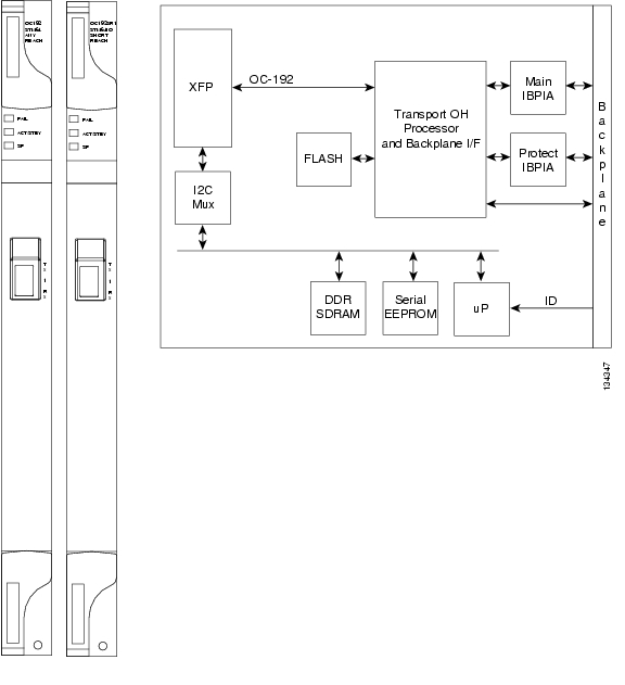
4.19 OC192SR1/STM64IO Short Reach and OC192/STM64 Any Reach Cards
Note
The OC192SR1/STM64IO Short Reach and OC192/STM64 Any Reach cards each provide a single OC-192/STM-64 interface, as follows:
•
•
In CTC, these cards are referred to as "OC192-XFP" cards.
The interface operates at 9.952 Gbps over single-mode fiber spans and can be provisioned for both concatenated and nonconcatenated payloads on a per STS-1/VC-4 basis. Specification references can be found for the OC-192/STM-64 interface in ITU-T G.691, ITU-T G.693, and ITU-T G.959.1, and Telcordia GR-253.
The optical interface uses a 10-Gbps form-factor pluggable (XFP) optical transceiver that plugs into a receptacle on the front of the card. The OC192SR1/STM64IO Short Reach card is used only with an SR-1 XFP, while the OC192/STM-64 Any Reach card can be provisioned for use with an SR-1, IR-2, or LR-2 XFP module. The XFP SR, IR, and LR interfaces each provide one bidirectional OC192/STM64 interface compliant with the recommendations defined by ITU-T G.91. SR-1 is compliant with ITU-T I-64.1, IR-2 is compliant with ITU G.691 S-64.2b, and LR-2 is compliant with ITU G.959.1 P1L1-2D2.
The cards are used only in Slots 5, 6, 12, and 13. and only with 10-Gbps cross-connect cards, such as the XC10G and XC-VXC-10G.
Note
Figure 4-22 shows the faceplates and block diagram for the two cards.
Figure 4-22 OC192SR1/STM64IO Short Reach and OC192/STM64 Any Reach Card Faceplates and Block Diagram
The cards' spans depend on the XFP module that is used:
•
•
•
4.19.1 OC192SR1/STM64IO Short Reach and OC192/STM64 Any Reach Card-Level Indicators
Table 4-22 describes the three card-level LEDs on the OC192SR1/STM64IO Short Reach and OC192/STM64 Any Reach cards.
4.19.2 OC192SR1/STM64IO Short Reach and OC-192/STM-64 Any Reach Port-Level Indicators
You can find the status of the OC192SR1/STM64IO Short Reach and OC192/STM64 Any Reach card ports by using the LCD screen on the ONS 15454 fan-tray assembly. Use the LCD to view the status of any port or card slot; the screen displays the number and severity of alarms for a given port or slot. Refer to the Cisco ONS 15454 Troubleshooting Guide for a complete description of the alarm messages.
4.20 Optical Card SFPs and XFPs
The ONS 15454 optical cards use industry-standard SFPs and XFP modular receptacles.
Currently, the only optical cards that use SFPs and XFPs are the 15454_MRC-12, OC192SR1/STM64IO Short Reach, and OC192/STM64 Any Reach cards.
For all optical cards, the type of SFP or XFP plugged into the card is displayed in CTC and TL1. Cisco offers SFPs and XFPs as separate orderable products.
4.20.1 Compatibility by Card
Table 4-23 lists Cisco ONS 15454 optical cards and their compatible SFPs and XFPs.
Caution
Table 4-23 SFP and XFP Card Compatibility
(Cisco Product ID)15454_MRC-12
(ONS 15454 SONET/SDH)ONS-SI-2G-S1
ONS-SI-2G-I1
ONS-SI-2G-L1
ONS-SI-2G-L2
ONS-SC-2G-30.3 through
ONS-SC-2G-60.6
ONS-SI-622-I1
ONS-SI-622-L1
ONS-SI-622-L2
ONS-SE-622-1470 through
ONS-SE-622-1610
ONS-SI-155-I1
ONS-SI-155-L1
ONS-SI-155-L2
ONS_SE-155-1470 through
ONS-SE-155-161010-1992-01
10-1993-01
10-2102-01
10-1990-01
10-2155-01 through
10-2186-01
10-1956-01
10-1958-01
10-1936-01
10-2004-01 through
10-2011-01
10-1938-01
10-1957-01
10-1937-01
10-1996-01 through
10-2003-01OC192SR1/STM64IO Short Reach (ONS 15454 SONET/SDH)1
ONS-XC-10G-S1
10-2012-01
OC192/STM64 Any Reach
(ONS 15454 SONET/SDH)1ONS-XC-10G-S1
ONS-XC-10G-I2
ONS-XC-10G-L210-2012-01
10-2193-01
10-2194-01
1 This card is designated as OC192-XFP in CTC
4.20.2 SFP Description
SFPs are integrated fiber optic transceivers that provide high-speed serial links from a port or slot to the network. Various latching mechanisms can be utilized on the modules. There is no correlation between the type of latch to the model type (such as SX or LX/LH) or technology type (such as Gigabit Ethernet). See the label on the SFP for technology type and model. Three latch types are available: mylar ( Figure 4-23), actuator/button ( Figure 4-24), and bail clasp ( Figure 4-25).
Figure 4-23 Mylar Tab SFP
Figure 4-24 Actuator/Button SFP
Figure 4-25 Bail Clasp SFP
SFP dimensions are:
•
•
•
SFP temperature ranges are:
•
•
•
4.20.3 XFP Description
The 10-Gbps 1310-nm and 1550-nm XFP transceivers are integrated fiber optic transceivers that provide high-speed serial links at the following signaling rates: 9.95 Gbps, 10.31 Gbps, and 10.51 Gbps. The XFP integrates the receiver and transmit path. The transmit side recovers and retimes the 10-Gbps serial data and passes it to a laser driver. The laser driver biases and modulates a 1310-nm or 1550-nm distributed feedback (DFB) laser, enabling data transmission over single-mode fiber (SMF) through an LC connector. The receive side recovers and retimes the 10-Gbps optical data stream from a positive-intrinsic-negative (PIN) photodetector, transimpedance amplifier and passes it to an output driver.
The XFP module uses the bail clasp latching mechanism, shown unlatched in Figure 4-26 and latched in Figure 4-27. See the label on the XFP for technology type and model.
Figure 4-26 Bail Clasp XFP (Unlatched)
Figure 4-27 Bail Clasp XFP (Latched)
XFP dimensions are:
•
•
•
XFP temperature ranges are:
•
•
•
4.20.4 PPM Provisioning
SFPs and XFPs are known as pluggable-port modules (PPMs) in the CTC. Multirate PPMs for the 15454_MRC-12 card can be provisioned for different line rates in CTC. For more information about provisioning PPMs, refer to the Cisco ONS 15454 Procedure Guide.
![]()
![]()
![]()
![]()
![]()
![]()
![]()
![]()
Posted: Wed Sep 5 06:49:12 PDT 2007
All contents are Copyright © 1992--2007 Cisco Systems, Inc. All rights reserved.
Important Notices and Privacy Statement.