|
|

Table Of Contents
5.2.2 E100T-12 Card-Level Indicators
5.2.3 E100T-12 Port-Level Indicators
5.2.4 Cross-Connect Compatibility
5.3.2 E100T-G Card-Level Indicators
5.3.3 E100T-G Port-Level Indicators
5.3.4 Cross-Connect Compatibility
5.4.2 E1000-2 Card-Level Indicators
5.4.3 E1000-2 Port-Level Indicators
5.4.4 Cross-Connect Compatibility
5.5.1 E1000-2-G Card-Level Indicators
5.5.2 E1000-2-G Port-Level Indicators
5.5.3 Cross-Connect Compatibility
5.6.2 G1000-4 Card-Level Indicators
5.6.3 G1000-4 Port-Level Indicators
5.7.3 G1K-4 Card-Level Indicators
5.7.4 G1K-4 Port-Level Indicators
5.8.1 ML100T-12 Card-Level Indicators
5.8.2 ML100T-12 Port-Level Indicators
5.8.3 Cross-Connect and Slot Compatibility
5.9.1 ML100X-8 Card-Level Indicators
5.9.2 ML100X-8 Port-Level Indicators
5.9.3 Cross-Connect and Slot Compatibility
5.10.1 ML1000-2 Card-Level Indicators
5.10.2 ML1000-2 Port-Level Indicators
5.10.3 Cross-Connect and Slot Compatibility
5.11.1 CE-100T-8 Card-Level Indicators
5.11.2 CE-100T-8 Port-Level Indicators
5.11.3 Cross-Connect and Slot Compatibility
5.12.1 CE-1000-4 Card-Level Indicators
5.12.2 CE-1000-4 Port-Level Indicators
5.12.3 Cross-Connect and Slot Compatibility
5.13 Ethernet Card GBICs and SFPs
5.13.3 G-1K-4 DWDM and CWDM GBICs
Ethernet Cards
Note
The terms "Unidirectional Path Switched Ring" and "UPSR" may appear in Cisco literature. These terms do not refer to using Cisco ONS 15xxx products in a unidirectional path switched ring configuration. Rather, these terms, as well as "Path Protected Mesh Network" and "PPMN," refer generally to Cisco's path protection feature, which may be used in any topological network configuration. Cisco does not recommend using its path protection feature in any particular topological network configuration.
The Cisco ONS 15454 integrates Ethernet into a SONET platform through the use of Ethernet cards. This chapter describes the E-Series, G-Series, ML-Series, and CE-Series Ethernet cards. For installation and card turn-up procedures, refer to the Cisco ONS 15454 Procedure Guide. For ML-Series configuration information, refer to the Ethernet Card Software Feature and Configuration Guide for the Cisco ONS 15454, Cisco ONS 15454 SDH, and Cisco ONS 15327.
Chapter topics include:
•
5.1 Ethernet Card Overview
The card overview section summarizes the Ethernet card functions and provides the software compatibility for each card.
Note
5.1.1 Ethernet Cards
Table 5-1 lists the Cisco ONS 15454 Ethernet cards.
Table 5-1 Ethernet Cards for the ONS 15454
E100T-12
The E100T-12 card provides 12 switched, autosensing, 10/100BaseT Ethernet ports and is compatible with the XCVT card.
See the "E100T-12 Card" section.
E100T-G
The E100T-G card provides 12 switched, autosensing, 10/100BaseT Ethernet ports and is compatible with the XC10G and XC-VXC-10G cards.
See the "E100T-G Card" section.
E1000-2
The E1000-2 card provides two IEEE-compliant, 1000-Mbps ports. Gigabit Interface Converters (GBICs) are separate.
See the "E1000-2 Card" section.
E1000-2-G
The E1000-2-G card provides two IEEE-compliant, 1000-Mbps ports. GBICs are separate. The E1000-2-G card is compatible with the XC10G and XC-VXC-10G cards.
See the "E1000-2-G Card" section.
G1000-4
The G1000-4 card provides four IEEE-compliant, 1000-Mbps ports. GBICs are separate. The G1000-4 requires the XC10G card.
See the "G1000-4 Card" section
G1K-4
The G1K-4 card provides four IEEE-compliant, 1000-Mbps ports. GBICs are separate. The G1K-4 card is functionally identical to the G1000-4 card, but can operate with XCVT, XC10G and XC-VXC-10G cross-connect cards.
See the "G1K-4 Card" section.
M100T-12
The ML100T-12 card provides 12 switched, autosensing, 10/100Base-T Ethernet ports.
See the "ML100T-12 Card" section.
M100X-8
The ML100X-8 card provides eight switched, 100BaseFX Ethernet ports.
See the "ML100X-8 Card" section.
M1000-2
The ML1000-2 card provides two IEEE-compliant, 1000-Mbps ports. Small form-factor pluggable (SFP) connectors are separate.
See the "ML1000-2 Card" section.
CE-100T-8
The CE-100T-8 card provides eight IEEE-compliant, 10/100-Mbps ports. The CE-100T-8 can operate with the XC10G, XC-VXC-10G, or XCVT cross-connect cards.
See the "CE-100T-8 Card" section.
CE-1000-4
The CE-1000-4 card provides four IEEE-compliant, 1000-Mbps ports. The CE-1000-4 card can operate with the XC10G, XC-VXC-10G, or XCVT cross-connect cards.
See the "CE-1000-4 Card" section.
5.1.2 Card Compatibility
Table 5-2 lists the CTC software compatibility for each Ethernet card.
Note
5.2 E100T-12 Card
Note
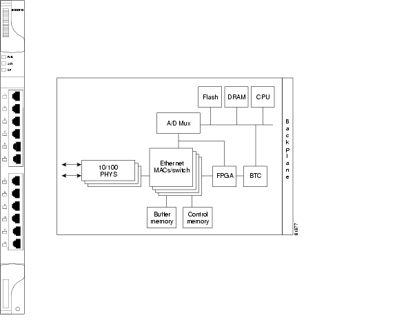
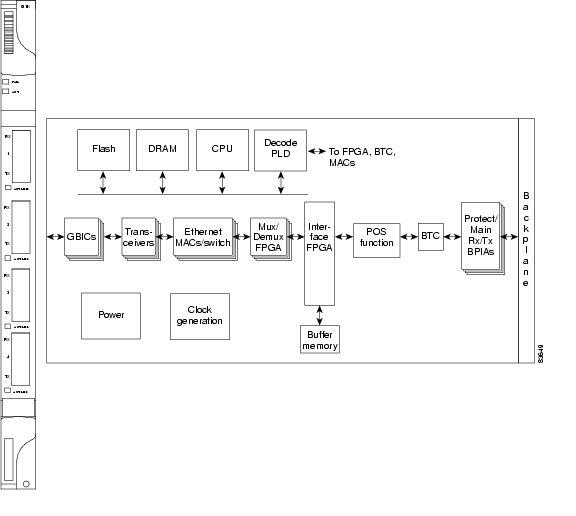
The ONS 15454 uses E100T-12 cards for Ethernet (10 Mbps) and Fast Ethernet (100 Mbps). Each card provides 12 switched, IEEE 802.3-compliant, 10/100BaseT Ethernet ports that can independently detect the speed of an attached device (autosense) and automatically connect at the appropriate speed. The ports autoconfigure to operate at either half or full duplex and determine whether to enable or disable flow control. You can also configure Ethernet ports manually. Figure 5-1 shows the faceplate and a block diagram of the card.
Figure 5-1 E100T-12 Faceplate and Block Diagram
The E100T-12 Ethernet card provides high-throughput, low-latency packet switching of Ethernet traffic across a SONET network while providing a greater degree of reliability through SONET self-healing protection services. This Ethernet capability enables network operators to provide multiple 10/100-Mbps access drops for high-capacity customer LAN interconnects, Internet traffic, and cable modem traffic aggregation. It enables the efficient transport and co-existence of traditional time-division multiplexing (TDM) traffic with packet-switched data traffic.
Each E100T-12 card supports standards-based, wire-speed, Layer 2 Ethernet switching between its Ethernet interfaces. The IEEE 802.1Q tag logically isolates traffic (typically subscribers). IEEE 802.1Q also supports multiple classes of service.
5.2.1 Slot Compatibility
You can install the E100T-12 card in Slots 1 to 6 and 12 to 17. Multiple E-Series Ethernet cards installed in an ONS 15454 can act independently or as a single Ethernet switch. You can create logical SONET ports by provisioning STS channels to the packet switch entity within the ONS 15454. Logical ports can be created with a bandwidth granularity of STS-1. The E100T-12 supports STS-1, STS-3c, STS-6c, and STS-12c circuit sizes.
Note
5.2.2 E100T-12 Card-Level Indicators
The E100T-12 card faceplate has two card-level LED indicators, described in Table 5-3.
5.2.3 E100T-12 Port-Level Indicators
The E100T-12 card has 12 pairs of LEDs (one pair for each port) to indicate port conditions. Table 5-4 lists the port-level indicators. You can find the status of the E100T-12 card port using the LCD on the ONS 15454 fan-tray assembly. Use the LCD to view the status of any port or card slot; the screen displays the number and severity of alarms for a given port or slot.
5.2.4 Cross-Connect Compatibility
The E100T-12 card is compatible with the XCVT card. Do not use the E100T-12 card with the XC10G and XC-VXC-10G cards.
5.3 E100T-G Card
Note
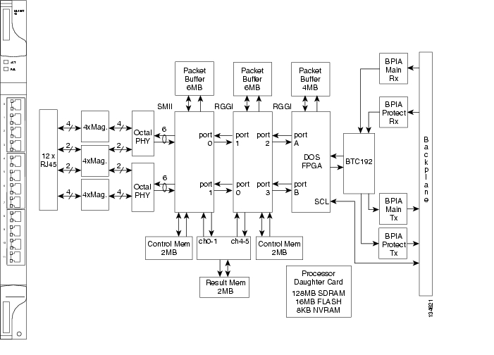
The ONS 15454 uses E100T-G cards for Ethernet (10 Mbps) and Fast Ethernet (100 Mbps). Each card provides 12 switched, IEEE 802.3-compliant, 10/100BaseT Ethernet ports that can independently detect the speed of an attached device (autosense) and automatically connect at the appropriate speed. The ports autoconfigure to operate at either half or full duplex and determine whether to enable or disable flow control. You can also configure Ethernet ports manually. Figure 5-2 shows the faceplate and a block diagram of the card.
Figure 5-2 E100T-G Faceplate and Block Diagram
The E100T-G Ethernet card provides high-throughput, low-latency packet switching of Ethernet traffic across a SONET network while providing a greater degree of reliability through SONET self-healing protection services. This Ethernet capability enables network operators to provide multiple 10/100 Mbps access drops for high-capacity customer LAN interconnects, Internet traffic, and cable modem traffic aggregation. It enables the efficient transport and co-existence of traditional TDM traffic with packet-switched data traffic.
Each E100T-G card supports standards-based, wire-speed, Layer 2 Ethernet switching between its Ethernet interfaces. The IEEE 802.1Q tag logically isolates traffic (typically subscribers). IEEE 802.1Q also supports multiple classes of service.
Note
5.3.1 Slot Compatibility
You can install the E100T-G card in Slots 1 to 6 and 12 to 17. Multiple E-Series Ethernet cards installed in an ONS 15454 can act independently or as a single Ethernet switch. You can create logical SONET ports by provisioning a number of STS channels to the packet switch entity within the ONS 15454. Logical ports can be created with a bandwidth granularity of STS-1. The ONS 15454 supports STS-1, STS-3c, STS-6c, or STS-12c circuit sizes.
5.3.2 E100T-G Card-Level Indicators
The E100T-G card faceplate has two card-level LED indicators, described in Table 5-5.
5.3.3 E100T-G Port-Level Indicators
The E100T-G card has 12 pairs of LEDs (one pair for each port) to indicate port conditions ( Table 5-6). You can find the status of the E100T-G card port using the LCD screen on the ONS 15454 fan-tray assembly. Use the LCD to view the status of any port or card slot; the screen displays the number and severity of alarms for a given port or slot.
5.3.4 Cross-Connect Compatibility
The E100T-G card is compatible with the XCVT, XC10G and XC-VXC-10G cards.
5.4 E1000-2 Card
Note
The ONS 15454 uses E1000-2 cards for Gigabit Ethernet (1000 Mbps). The E1000-2 card provides two IEEE-compliant, 1000-Mbps ports for high-capacity customer LAN interconnections. Each port supports full-duplex operation.
The E1000-2 card uses GBIC modular receptacles for the optical interfaces. For details, see the "Ethernet Card GBICs and SFPs" section.
Figure 5-3 shows the card faceplate and a block diagram of the card.
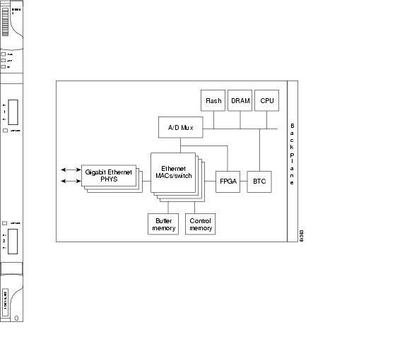
Figure 5-3 E1000-2 Faceplate and Block Diagram
The E1000-2 Gigabit Ethernet card provides high-throughput, low-latency packet switching of Ethernet traffic across a SONET network while providing a greater degree of reliability through SONET self-healing protection services. This enables network operators to provide multiple 1000-Mbps access drops for high-capacity customer LAN interconnects. It enables efficient transport and co-existence of traditional TDM traffic with packet-switched data traffic.
Each E1000-2 card supports standards-based, Layer 2 Ethernet switching between its Ethernet interfaces and SONET interfaces on the ONS 15454. The IEEE 802.1Q VLAN tag logically isolates traffic (typically subscribers).
Multiple E-Series Ethernet cards installed in an ONS 15454 can act together as a single switching entity or as independent single switches supporting a variety of SONET port configurations.
You can create logical SONET ports by provisioning STS channels to the packet switch entity within the ONS 15454. Logical ports can be created with a bandwidth granularity of STS-1. The ONS 15454 supports STS-1, STS-3c, STS-6c, or STS-12c circuit sizes.
Note
5.4.1 Slot Compatibility
You can install the E1000-2 card in Slots 1 to 6 and 12 to 17. The E1000-2 is compatible with the XCVT card but not the XC10G or and XC-VXC-10G cards. The E1000-2-G is compatible with the XC10G and XC-VXC-10G.
5.4.2 E1000-2 Card-Level Indicators
The E1000-2 card faceplate has two card-level LED indicators, described in Table 5-7.
5.4.3 E1000-2 Port-Level Indicators
The E1000-2 card has one bicolor LED per port ( Table 5-8). When the LED is solid green, it indicates that carrier is detected, meaning an active network cable is installed. When the LED is off, it indicates that an active network cable is not plugged into the port, or the card is carrying unidirectional traffic. When the LED flashes amber, it does so at a rate proportional to the level of traffic being received and transmitted over the port.
5.4.4 Cross-Connect Compatibility
The E1000-2 is compatible with XCVT cards. The XC10G and XC-VXC-10G cards require the E1000-2-G card.
5.5 E1000-2-G Card
Note
The ONS 15454 uses E1000-2-G cards for Gigabit Ethernet (1000 Mbps). The E1000-2-G card provides two IEEE-compliant, 1000-Mbps ports for high-capacity customer LAN interconnections. Each port supports full-duplex operation.
The E1000-2-G card uses GBIC modular receptacles for the optical interfaces. For details, see the "Ethernet Card GBICs and SFPs" section.
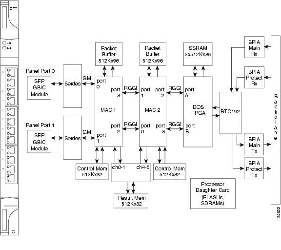
Figure 5-4 shows the card faceplate and a block diagram of the card.
Figure 5-4 E1000-2-G Faceplate and Block Diagram
The E1000-2-G Gigabit Ethernet card provides high-throughput, low-latency packet switching of Ethernet traffic across a SONET network while providing a greater degree of reliability through SONET self-healing protection services. This enables network operators to provide multiple 1000-Mbps access drops for high-capacity customer LAN interconnects. It enables efficient transport and co-existence of traditional TDM traffic with packet-switched data traffic.
Each E1000-2-G card supports standards-based, Layer 2 Ethernet switching between its Ethernet interfaces and SONET interfaces on the ONS 15454. The IEEE 802.1Q VLAN tag logically isolates traffic (typically subscribers).
Multiple E-Series Ethernet cards installed in an ONS 15454 can act together as a single switching entity or as independent single switches supporting a variety of SONET port configurations.
You can create logical SONET ports by provisioning STS channels to the packet switch entity within the ONS 15454. Logical ports can be created with a bandwidth granularity of STS-1. The ONS 15454 supports STS-1, STS-3c, STS-6c, or STS-12c circuit sizes.
Note
5.5.1 E1000-2-G Card-Level Indicators
The E1000-2-G card faceplate has two card-level LED indicators, described in Table 5-9.
5.5.2 E1000-2-G Port-Level Indicators
The E1000-2-G card has one bicolor LED per port ( Table 5-10). When the green LINK LED is on, carrier is detected, meaning an active network cable is installed. When the green LINK LED is off, an active network cable is not plugged into the port, or the card is carrying unidirectional traffic. The amber port ACT LED flashes at a rate proportional to the level of traffic being received and transmitted over the port.
5.5.3 Cross-Connect Compatibility
The E1000-2-G is compatible with the XCVT, XC10G, and XC-VXC-10G cards. You can install the card in Slots 1 to 6 and 12 to 17.
5.6 G1000-4 Card
The G1000-4 card requires the XC10G card. The ONS 15454 uses G1000-4 cards for Gigabit Ethernet (1000 Mbps). The G1000-4 card provides four ports of IEEE-compliant, 1000-Mbps interfaces. Each port supports full-duplex operation for a maximum bandwidth of OC-48 on each card.
The G1000-4 card uses GBIC modular receptacles for the optical interfaces. For details, see the "Ethernet Card GBICs and SFPs" section.
Note
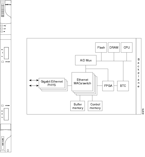
Figure 5-5 shows the card faceplate and the block diagram of the card.
Figure 5-5 G1000-4 Faceplate and Block Diagram
The G1000-4 Gigabit Ethernet card provides high-throughput, low latency transport of Ethernet encapsulated traffic (IP and other Layer 2 or Layer 3 protocols) across a SONET network. Carrier-class Ethernet transport is achieved by hitless (< 50 ms) performance in the event of any failures or protection switches (such as 1+1 automatic protection switching [APS], path protection, or bidirectional line switch ring [BLSR]). Full provisioning support is possible through Cisco Transport Controller (CTC), Transaction Language One (TL1), or Cisco Transport Manager (CTM).
The circuit sizes supported are STS-1, STS-3c, STS-6c, STS-9c, STS-12c, STS-24c, and STS-48c.
5.6.1 STS-24c Restriction
Due to hardware constraints, the card imposes an additional restriction on the combinations of circuits that can be dropped onto a G-Series card. These restrictions are transparently enforced by the ONS 15454, and you do not need to keep track of restricted circuit combinations.
When a single STS-24c terminates on a card, the remaining circuits on that card can be another single STS-24c or any combination of circuits of STS-12c size or less that add up to no more than 12 STSs (that is a total of 36 STSs on the card).
If STS-24c circuits are not being dropped on the card, the full 48 STSs bandwidth can be used with no restrictions (for example, using either a single STS-48c or 4 STS-12c circuits).
Note
5.6.2 G1000-4 Card-Level Indicators
The G1000-4 card faceplate has two card-level LED indicators, described in Table 5-11.
5.6.3 G1000-4 Port-Level Indicators
The G1000-4 card has one bicolor LED per port. Table 5-12 describes the status that each color represents.
5.6.4 Slot Compatibility
The G1000-4 card requires Cisco ONS 15454 Release 3.2 or later system software and the XCVT, XC10G cross-connect card. You can install the card in Slots 1 to 6 and 12 to 17, for a total shelf capacity of 48 Gigabit Ethernet ports. The practical G1000-4 port per shelf limit is 40, because at least two slots are typically filled by OC-N trunk cards such as the OC-192.
5.7 G1K-4 Card
Note
The G1K-4 card is the functional equivalent of the earlier G1000-4 card and provides four ports of IEEE-compliant, 1000-Mbps interfaces. Each interface supports full-duplex operation for a maximum bandwidth of 1 Gbps or 2 Gbps bidirectional per port, and 2.5 Gbps or 5 Gbps bidirectional per card. Each port autonegotiates for full duplex and IEEE 802.3x flow control. The G1K-4 card uses GBIC modular receptacles for the optical interfaces. For details, see the "Ethernet Card GBICs and SFPs" section.
Figure 5-6 shows the card faceplate and the block diagram of the card.
Figure 5-6 G1K-4 Faceplate and Block Diagram
The G1K-4 Gigabit Ethernet card provides high-throughput, low-latency transport of Ethernet encapsulated traffic (IP and other Layer 2 or Layer 3 protocols) across a SONET network while providing a greater degree of reliability through SONET self-healing protection services. Carrier-class Ethernet transport is achieved by hitless (< 50 ms) performance in the event of any failures or protection switches (such as 1+1 APS, path protection, BLSR, or optical equipment protection) and by full provisioning and manageability, as in SONET service. Full provisioning support is possible through CTC or CTM. Each G1K-4 card performs independently of the other cards in the same shelf.
5.7.1 STS-24c Restriction
Due to hardware constraints, the card imposes an additional restriction on the combinations of circuits that can be dropped onto a G-Series card. These restrictions are transparently enforced by the ONS 15454, and you do not need to keep track of restricted circuit combinations.
When a single STS-24c terminates on a card, the remaining circuits on that card can be another single STS-24c or any combination of circuits of STS-12c size or less that add up to no more than 12 STSs (that is a total of 36 STSs on the card).
If STS-24c circuits are not being dropped on the card, the full 48 STSs bandwidth can be used with no restrictions (for example, using either a single STS-48c or 4 STS-12c circuits).
Note
5.7.2 G1K-4 Compatibility
The G1K-4 card operates with the XCVT, XC10G or XC-VXC-10G cards. With the XC10G or XC-VXC-10G cards, you can install the G1K-4 card in Slots 1 to 6 and 12 to 17, for a total shelf capacity of 48 Gigabit Ethernet ports. (The practical limit is 40 ports because at least two slots are typically populated by optical cards such as OC-192). When used with the XCVT cards, the G1K-4 is limited to Slots 5, 6, 12, and 13.
5.7.3 G1K-4 Card-Level Indicators
The G1K-4 card faceplate has two card-level LED indicators, described in Table 5-13.
5.7.4 G1K-4 Port-Level Indicators
The G1K-4 card has four bicolor LEDs (one LED per port). Table 5-14 describes the status that each color represents.
5.8 ML100T-12 Card
Note
The ML100T-12 card provides 12 ports of IEEE 802.3-compliant, 10/100 interfaces. Each interface supports full-duplex operation for a maximum bandwidth of 200 Mbps per port and 2.488 Gbps per card. Each port independently detects the speed of an attached device (autosenses) and automatically connects at the appropriate speed. The ports autoconfigure to operate at either half or full duplex and can determine whether to enable or disable flow control. For ML-Series configuration information, see the Ethernet Card Software Feature and Configuration Guide for the Cisco ONS 15454, Cisco ONS 15454 SDH, and Cisco ONS 15327.
Figure 5-7 shows the card faceplate and block diagram.
Caution
Figure 5-7 ML100T-12 Faceplate and Block Diagram
The card features two virtual packet over SONET (POS) ports with a maximum combined bandwidth of STS-48. The ports function in a manner similar to OC-N card ports, and each port carries an STS circuit with a size of STS-1, STS-3c, STS-6c, STS-9c, STS-12c, or STS-24c. To configure an ML-Series card SONET STS circuit, refer to the "Create Circuits and VT Tunnels" chapter of the Cisco ONS 15454 Procedure Guide.
The ML-Series POS ports supports virtual concatenation (VCAT) of SONET circuits and a software link capacity adjustment scheme (SW-LCAS). The ML-Series card supports a maximum of two VCAT groups with each group corresponding to one of the POS ports. Each VCAT group must be provisioned with two circuit members. An ML-Series card supports STS-1c-2v, STS-3c-2v and STS-12c-2v. To configure an ML-Series card SONET VCAT circuit, refer to the "Create Circuits and VT Tunnels" chapter of the Cisco ONS 15454 Procedure Guide.
5.8.1 ML100T-12 Card-Level Indicators
The ML00T-12 card supports two card-level LED indicators. The card-level indicators are described in Table 5-15.
5.8.2 ML100T-12 Port-Level Indicators
The ML100T-12 card provides a pair of LEDs for each Fast Ethernet port: an amber LED for activity (ACT) and a green LED for LINK. The port-level indicators are described in Table 5-16.
5.8.3 Cross-Connect and Slot Compatibility
The ML100T-12 card works in Slots 1 to 6 or 12 to 17 with the XC10G or XC-VXC-10G card. It works only in Slots 5, 6, 12, or 13 with the XCVT card.
5.9 ML100X-8 Card
Note
The ML100X-8 card provides eight ports with 100 base FX interfaces. The FX interfaces support one of two connectors, an LX SFP or an FX SFP. The LX SFP is a 100 Mbps 802.3-compliant SFP that operates over a pair of single-mode optical fibers and includes LC connectors. The FX SFP is a 100 Mbps 802.3- compliant SFP that operates over a pair of multimode optical fibers and includes LC connectors. For more information on SFPs, see the "Ethernet Card GBICs and SFPs" section.
Each interface supports full-duplex operation for autonegotiation and a maximum bandwidth of 200 Mbps per port and 2.488 Gbps per card. For ML-Series configuration information, see the Ethernet Card Software Feature and Configuration Guide for the Cisco ONS 15454, Cisco ONS 15454 SDH, and Cisco ONS 15327.
Figure 5-8 shows the card faceplate and block diagram.
Figure 5-8 ML100X-8 Faceplate and Block Diagram
The card features two virtual packet over SONET (POS) ports with a maximum combined bandwidth of STS-48. The ports function in a manner similar to OC-N card ports, and each port carries an STS circuit with a size of STS-1, STS-3c, STS-6c, STS-9c, STS-12c, or STS-24c. To configure an ML-Series card SONET STS circuit, refer to the "Create Circuits and VT Tunnels" chapter of the Cisco ONS 15454 Procedure Guide.
The ML-Series POS ports supports virtual concatenation (VCAT) of SONET circuits and a software link capacity adjustment scheme (SW-LCAS). The ML-Series cards support a maximum of two VCAT groups with each group corresponding to one of the POS ports. Each VCAT group must be provisioned with two circuit members. An ML-Series card supports STS-1c-2v, STS-3c-2v and STS-12c-2v. To configure an ML-Series-card SONET VCAT circuit, refer to the "Create Circuits and VT Tunnels" chapter of the Cisco ONS 15454 Procedure Guide.
5.9.1 ML100X-8 Card-Level Indicators
The ML100X-8 card supports two card-level LED indicators. Table 5-17 describes the card-level indicators.
5.9.2 ML100X-8 Port-Level Indicators
The ML100X-8 card provides a pair of LEDs for each Fast Ethernet port: an amber LED for activity (ACT) and a green LED for LINK. Table 5-18 describes the port-level indicators.
5.9.3 Cross-Connect and Slot Compatibility
The ML100X-8 card operates in Slots 1 to 6 or 12 to 17 with the XC10G or XC-VXC-10G cards. It operates only in Slots 5, 6, 12, or 13 with the XCVT card.
5.10 ML1000-2 Card
Note
The ML1000-2 card provides two ports of IEEE-compliant, 1000-Mbps interfaces. Each interface supports full-duplex operation for a maximum bandwidth of 2 Gbps per port and 4 Gbps per card. Each port autoconfigures for full duplex and IEEE 802.3x flow control.
SFP modules are offered as separate orderable products for maximum customer flexibility. For details, see the "Ethernet Card GBICs and SFPs" section.
Figure 5-9 shows the ML1000-2 card faceplate.
Figure 5-9 ML1000-2 Faceplate
The card features two virtual packet over SONET (POS) ports with a maximum combined bandwidth of STS-48. The ports function in a manner similar to OC-N card ports, and each port carries an STS circuit with a size of STS-1, STS-3c, STS-6c, STS-9c, STS-12c, or STS-24c. To configure an ML-Series card SONET STS circuit, refer to the "Create Circuits and VT Tunnels" chapter of the Cisco ONS 15454 Procedure Guide.
The ML-Series POS ports supports VCAT of SONET circuits and a software link capacity adjustment scheme (SW-LCAS). The ML-Series card supports a maximum of two VCAT groups with each group corresponding to one of the POS ports. Each VCAT group must be provisioned with two circuit members. An ML-Series card supports STS-1c-2v, STS-3c-2v and STS-12c-2v. To configure an ML-Series card SONET VCAT circuit, refer to the "Create Circuits and VT Tunnels" chapter of the Cisco ONS 15454 Procedure Guide.
5.10.1 ML1000-2 Card-Level Indicators
The ML1000-2 card faceplate has two card-level LED indicators, described in Table 5-19.
5.10.2 ML1000-2 Port-Level Indicators
The ML1000-2 card has three LEDs for each of the two Gigabit Ethernet ports, described in Table 5-20.
5.10.3 Cross-Connect and Slot Compatibility
The ML1000-2 card is compatible in Slots 1 to 6 or 12 to 17 with the XC10G or XC-VXC-10G card. It is only compatible in Slots 5, 6, 12, or 13 with the XCVT card.
5.11 CE-100T-8 Card
Note
The CE-100T-8 card provides eight RJ-45 10/100 Mbps Ethernet ports and an RJ-45 console port on the card faceplate. The CE-100T-8 card provides mapping of 10/100 Mbps Ethernet traffic into SONET STS-12 payloads, making use of low-order (VT1.5) virtual concatenation, high-order (STS-1) virtual concatenation, generic framing procedure (GFP), and point-to-point protocol/high-level data link control (PPP/HDLC) framing protocols.
The CE-100T8 card also supports the link capacity adjustment scheme (LCAS), which allows hitless dynamic adjustment of SONET link bandwidth. The CE-100T-8 card's LCAS is hardware-based, but the CE-100T-8 also supports SW-LCAS. This makes it compatible with the ONS 15454 SDH ML-Series card, which supports only SW-LCAS and does not support the standard hardware-based LCAS. SW-LCAS is supported when a circuit from the CE-100T-8 terminates on the ONS 15454 SDH ML-Series card.
The circuit types supported are:
•
•
•
•
Each 10/100 Ethernet port can be mapped to a SONET channel in increments of VT1.5 or STS-1 granularity, allowing efficient transport of Ethernet and IP over the SONET infrastructure.
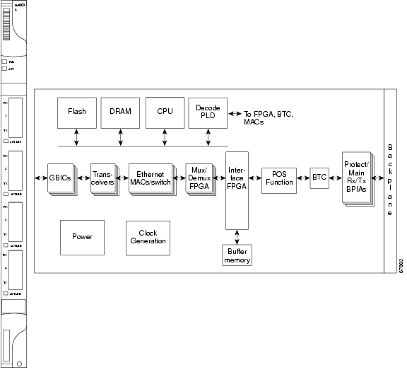
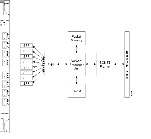
Figure 5-10 shows the CE-100T-8 card faceplate and block diagram.
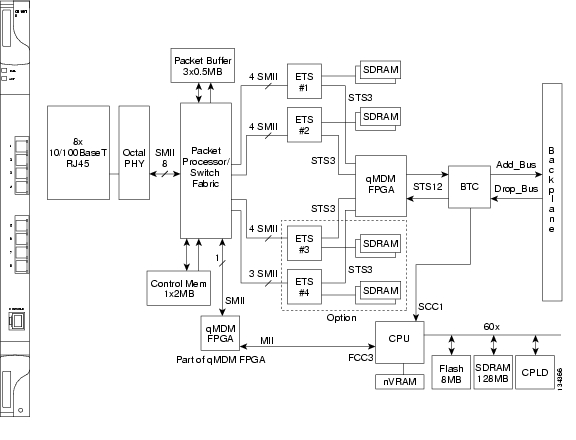
Figure 5-10 CE-100T-8 Faceplate and Block Diagram
The following paragraphs describe the general functions of the CE-100T-8 card and relate to the block diagram.
In the ingress direction, (Ethernet-to-SONET), the PHY, which performs all of the physical layer interface functions for 10/100 Mbps Ethernet, sends the frame to the network processor for queuing in the respective packet buffer memory. The network processor performs packet processing, packet switching, and classification. The Ethernet frames are then passed to the Ethermap where Ethernet traffic is terminated and is encapsulated using HDLC or GFP framing on a per port basis. The encapsulated Ethernet frames are then mapped into a configurable number of virtual concatenated low and high order payloads, such as VT1.5 synchronous payload envelope (SPE), STS-1 SPE, or a contiguous concatenated payload such as STS-3c SPE. Up to 64 VT1.5 SPEs or 3 STS-1 SPEs can be virtually concatenated. The SONET SPE carrying encapsulated Ethernet frames are passed onto the qMDM FPGA, where four STS-3 frames are multiplexed to form a STS-12 frame for transport over the SONET network by means of the Bridging Convergence Transmission (BTC) ASIC.
In the Egress direction (SONET-to-Ethernet), the FPGA extracts four STS-3 SPEs from the STS-12 frame it receives from the BTC and sends each of the STS-3s to the ET3 mappers. The STS-3 SONET SPE carrying GFP or PPP/HDLC encapsulated Ethernet frames is then extracted and buffered in Ethermap's external memory. This memory is used for providing alignment and differential delay compensation for the received low-order and high-order virtual concatenated payloads. After alignment and delay compensation have been done, the Ethernet frames are decapsulated with one of the framing protocols (GFP or HDLC). Decapsulated Ethernet frames are then passed onto the network processor for QoS queuing and traffic scheduling. The network processor switches the frame to one of the corresponding PHY channels and then to the Ethernet port for transmission to the external client(s).
For information on the CE-100T-8 QoS features, refer to the "CE-100T-8 Operations" chapter of the Ethernet Card Software Feature and Configuration Guide for the Cisco ONS 15454, Cisco ONS 15454, and Cisco ONS 15327.
5.11.1 CE-100T-8 Card-Level Indicators
The CE-100T-8 card faceplate has two card-level LED indicators, described in Table 5-21.
5.11.2 CE-100T-8 Port-Level Indicators
The CE-100T-8 card has two LEDs embedded into each of the eight Ethernet port RJ-45 connectors. The LEDs are described in Table 5-22.
5.11.3 Cross-Connect and Slot Compatibility
The CE-100T-8 card is compatible in Slots 1 to 6 or 12 to 17 with the XC10G, XC-VXC-10G, or XCVT cards.
5.12 CE-1000-4 Card
Note
The CE-1000-4 card uses pluggable Gigabit Interface Converters (GBICs) to transport Ethernet traffic over a SONET network. The CE-1000-4 provides four IEEE 802.3-compliant, 1000-Mbps Gigabit Ethernet ports at the ingress. At the egress, the CE-1000-4 card provides an integrated Ethernet over SONET mapper with four virtual ports to transfer Ethernet packets over a SONET network.
The Ethernet ports automatically configure to operate at either half or full duplex and can determine whether to enable or disable flow control. The Ethernet ports can also be oversubscribed using flow control.
The Ethernet frames are encapsulated using the ITU-T generic framing procedure (GFP) (with or without CRC) or LEX, the point-to-point protocol (PPP) with high-level data link control (HDLC). The CE-1000-4 card can interoperate with G1000-4/G1K-4 cards (using LEX encapsulation), CE-100T-8 cards (using LEX or GFP-F), and ML-Series cards (using LEX or GFP-F).
The Ethernet frames can be mapped into:
•
–
–
•
–
–
To configure a CE-1000-4 card SONET STS or VCAT circuit, refer to the "Create Circuits and Tunnels" chapter in the Cisco ONS 15454 Procedure Guide.
The CE-1000-4 card provides multiple management options through Cisco Transport Controller (CTC), Cisco Transport Manager (CTM), Transaction Language 1 (TL1), and Simple Network Management Protocol (SNMP).
The CE-1000-4 card supports the software link capacity adjustment scheme (SW-LCAS). This makes it compatible with the ONS 15454 CE-100T-8 and ML-Series cards. The CE-1000-4 card supports VCAT groups (VCGs) that are reconfigurable when SW-LCAS is enabled (flexible VCGs). The CE-1000-4 card does not support the standard hardware-based LCAS.
The following guidelines apply to flexible VCGs:
•
•
•
•
•
•
The CE-1000-4 card supports a non link capacity adjustment scheme (no-LCAS). This also makes it compatible with the ONS 15454 CE-100T-8 and ML-Series cards. The CE-1000-4 card supports VCAT groups (VCGs) that are fixed and not reconfigurable when no-LCAS is enabled (fixed VCGs).
The following guidelines apply to fixed VCGs:
•
•
Note
•
The CE-1000-4 card supports VCAT differential delay and provides these associated features:
•
•
•
•
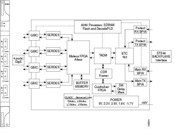
Figure 5-11 shows the CE-1000-4 card faceplate and block diagram.
Figure 5-11 CE-1000-4 Faceplate and Block Diagram
5.12.1 CE-1000-4 Card-Level Indicators
The CE-1000-4 card faceplate has two card-level LED indicators, described in Table 5-23.
Note
5.12.2 CE-1000-4 Port-Level Indicators
The CE-1000-4 card provides a pair of LEDs for each Gigabit Ethernet port: an amber LED for activity (ACT) and a green LED for link stat us (LINK). Table 5-24 describes the status that each color represents.
5.12.3 Cross-Connect and Slot Compatibility
The CE-1000-4 card can be installed in Slots 1 to 6 and 12 to 17 when used with the XC10G and XC-VXC-10G cards. When the shelf uses the XCVT card, the CE-1000-4 card can only be installed in Slots 5, 6, 12, and 13.
5.13 Ethernet Card GBICs and SFPs
This section describes the GBICs and SFPs used with the Ethernet cards.
The ONS 15454 Ethernet cards use industry standard small form-factor pluggable connectors (SFPs) and gigabit interface converter (GBIC) modular receptacles. The ML-Series Gigabit Ethernet cards use standard Cisco SFPs. The Gigabit E-Series, G-1K-4, and CE-1000-4 cards use standard Cisco GBICs. With Software Release 4.1 and later, G-Series cards can also be equipped with dense wavelength division multiplexing (DWDM) and coarse wavelength division multiplexing (CWDM) GBICs to function as Gigabit Ethernet transponders.
For all Ethernet cards, the type of GBIC or SFP plugged into the card is displayed in CTC and TL1. Cisco offers SFPs and GBICs as separate orderable products.
5.13.1 Compatibility by Card
Table 5-25 lists Cisco ONS 15454 Ethernet cards with their compatible GBICs and SFPs.
Caution
Table 5-25 GBIC and SFP Card Compatibility
(Cisco Product ID)E1000-2-G (ONS 15454 SONET)
E1000-2 (ONS 15454 SONET/SDH)15454-GBIC-SX
15454E-GBIC-SX
15454-GBIC-LX/LH
15454E-GBIC-LX/LH30-0759-01
800-06780-011
10-1743-01
30-0703-01G1K-4 (ONS 15454 SONET/SDH)
G1000-4 (ONS 15454 SONET/SDH)15454-GBIC-SX
15454E-GBIC-SX
15454-GBIC-LX/LH
15454E-GBIC-LX/LH
15454-GBIC-ZX
15454E-GBIC-ZX
15454-GBIC-xx.x2
15454E-GBIC-xx.x 2
15454-GBIC-xxxx3
15454E-GBIC-xxxx 330-0759-01
800-06780-01
10-1743-01
30-0703-01
30-0848-01
10-1744-01
10-1845-01 through 10-1876-01
10-1845-01 through 10-1876-01
10-1453-01 through 10-1460-01
10-1453-01 through 10-1460-01ML1000-2 (ONS 15454 SONET/SDH)
15454-SFP-LC-SX
15454E-SFP-LC-SX
ONS-SC-GE-SX
15454-SFP-LC-LX/LH
15454E-SFP-LC-LX/LH
ONS-SC-GE-LX30-1301-01
30-1301-01
10-2301-01
30-1299-01
30-1299-01
10-2298-01ML100X-8 (ONS 15454 SONET/SDH)
ONS-SE-100-FX
ONS-SE-100-LX1010-2212-01
10-2213-01CE-1000-4 (ONS 15454 SONET/SDH)
15454-GBIC-SX
15454-GBIC-LX
15454-GBIC-ZX
ONS-GC-GE-SX
ONS-GC-GE-LX
ONS-GC-GE-ZX30-0759-01
10-1743-01
30-0848-01
10-2192-01
10-2191-01
10-2190-01
1 This TAN is only compatible with ONS 15454-E1000-2 or 15454-E1000-2-G cards.
2 xx.x defines the 32 possible wavelengths Table 5-27.
3 xxxx defines the 8 possible wavelengths as shown in Table 5-26.
5.13.2 GBIC Description
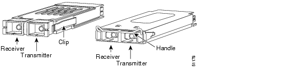
GBICs are integrated fiber optic transceivers that provide high-speed serial links from a port or slot to the network. Various latching mechanisms can be utilized on the GBIC pluggable modules. There is no correlation between the type of latch and the model type (such as SX or LX/LH) or technology type (such as Gigabit Ethernet). See the label on the GBIC for technology type and model. One GBIC model has two clips (one on each side of the GBIC) that secure the GBIC in the slot on the Ethernet card; the other has a locking handle. Both types are shown in Figure 5-12.
GBIC dimensions are:
•
•
•
GBIC temperature ranges are:
•
•
•
Figure 5-12 GBICs with Clips (left) and with a Handle (right)
5.13.3 G-1K-4 DWDM and CWDM GBICs
DWDM (15454-GBIC-xx.x, 15454E-GBIC-xx.x) and CWDM (15454-GBIC-xxxx, 15454E-GBIC-xxxx) GBICs operate in an ONS 15454 G-Series card when the card is configured in Gigabit Ethernet Transponding mode or in Ethernet over SONET mode. DWDM and CWDM GBICs are both wavelength division multiplexing (WDM) technologies and operate over single-mode fibers with SC connectors. Cisco CWDM GBIC technology uses a 20 nm wavelength grid and Cisco ONS 15454 DWDM GBIC technology uses a 1 nm wavelength grid. CTC displays the specific wavelengths of the installed CWDM or DWDM GBICs. DWDM wavelengths are spaced closer together and require more precise lasers than CWDM. The DWDM spectrum allows for optical signal amplification. For more information on G-Series card transponding mode, refer to the Ethernet Card Software Feature and Configuration Guide for the Cisco ONS 15454, Cisco ONS 15454 SDH, and Cisco ONS 15327.
The DWDM and CWDM GBICs receive across the full 1300 nm and 1500 nm bands, which includes all CWDM, DWDM, LX/LH, ZX wavelengths, but transmit on one specified wavelength. This capability can be exploited in some of the G-Series transponding modes by receiving wavelengths that do not match the specific transmission wavelength.
Note
The ONS 15454-supported CWDM GBICs reach up to 100 to 120 km over single-mode fiber and support eight wavelengths as shown in Table 5-26.
The ONS 15454-supported DWDM GBICs reach up to 100 to 120 km over single-mode fiber and support 32 different wavelengths in the red and blue bands. Paired with optical amplifiers, such as the Cisco ONS 15216, the DWDM GBICs allow maximum unregenerated spans of approximately 300 km ( Table 5-27).
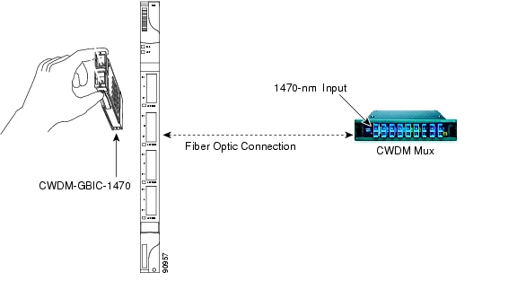
CWDM or DWDM GBICs for the G-Series card come in set wavelengths and are not provisionable. The wavelengths are printed on each GBIC, for example, CWDM-GBIC-1490. The user must insert the specific GBIC transmitting the wavelength required to match the input of the CWDM/DWDM device for successful operation ( Figure 5-13). Follow your site plan or network diagram for the required wavelengths.
Figure 5-13 CWDM GBIC with Wavelength Appropriate for Fiber-Connected Device
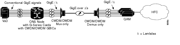
A G-Series card equipped with CWDM or DWDM GBICs supports the delivery of unprotected Gigabit Ethernet service over Metro DWDM ( Figure 5-14). It can be used in short-haul and long-haul applications.
Figure 5-14 G-Series with CWDM/DWDM GBICs in Cable Network
5.13.4 SFP Description
SFPs are integrated fiber-optic transceivers that provide high-speed serial links from a port or slot to the network. Various latching mechanisms can be utilized on the SFP modules. There is no correlation between the type of latch and the model type (such as SX or LX/LH) or technology type (such as Gigabit Ethernet). See the label on the SFP for technology type and model. One type of latch available is a mylar tab ( Figure 5-15), a second type of latch available is an actuator/button ( Figure 5-16), and a third type of latch is a bail clasp ( Figure 5-17).
SFP dimensions are:
•
•
•
SFP temperature ranges for are:
•
•
•
Figure 5-15 Mylar Tab SFP
Figure 5-16 Actuator/Button SFP
Figure 5-17 Bail Clasp SFP
![]()
![]()
![]()
![]()
![]()
![]()
![]()
![]()
Posted: Tue Nov 20 22:17:56 PST 2007
All contents are Copyright © 1992--2007 Cisco Systems, Inc. All rights reserved.
Important Notices and Privacy Statement.