|
|

Table Of Contents
3.2.1 EC1-12 Slots and Connectors
3.2.2 EC1-12 Faceplate and Block Diagram
3.2.3 EC1-12 Hosted by XCVT, XC10G, or XC-VXC-10G
3.2.4 EC1-12 Card-Level Indicators
3.2.5 EC1-12 Port-Level Indicators
3.3.1 DS1N-14 Features and Functions
3.3.2 DS1-14 and DS1N-14 Slot Compatibility
3.3.3 DS1-14 and DS1N-14 Faceplate and Block Diagram
3.3.4 DS1-14 and DS1N-14 Hosted by XCVT, XC10G, or XC-VXC-10G
3.3.5 DS1-14 and DS1N-14 Card-Level Indicators
3.3.6 DS1-14 and DS1N-14 Port-Level Indicators
3.4.1 DS1/E1-56 Slots and Connectors
3.4.2 DS1/E1-56 Faceplate and Block Diagram
3.4.3 DS1/E1-56 Card-Level Indicators
3.4.4 DS1/E1-56 Port-Level Indicators
3.5.1 DS3-12 and DS3N-12 Slots and Connectors
3.5.2 DS3-12 and DS3N-12 Faceplate and Block Diagram
3.5.3 DS3-12 and DS3N-12 Card-Level Indicators
3.5.4 DS3-12 and DS3N-12 Port-Level Indicators
3.6.1 DS3/EC1-48 Slots and Connectors
3.6.2 DS3/EC1-48 Faceplate and Block Diagram
3.6.3 DS3/EC1-48 Card-Level Indicators
3.6.4 DS3/EC1-48 Port-Level Indicators
3.7.1 DS3i-N-12 Slots and Connectors
3.7.2 DS3i-N-12 Card-Level Indicators
3.7.3 DS3i-N-12 Port-Level Indicators
3.8 DS3-12E and DS3N-12E Cards
3.8.1 DS3-12E and DS3N-12E Slots and Connectors
3.8.2 DS3-12E Faceplate and Block Diagram
3.8.3 DS3-12E and DS3N-12E Card-Level Indicators
3.8.4 DS3-12E and DS3N-12E Port-Level Indicators
3.9.1 DS3XM-6 Slots and Connectors
3.9.2 DS3XM-6 Faceplate and Block Diagram
3.9.3 DS3XM-6 Hosted By XCVT, XC10G, XC-VXC-10G
3.9.4 DS3XM-6 Card-Level Indicators
3.9.5 DS3XM-6 Port-Level Indicators
3.10.1 Backplane Configurations
3.10.7 DS3XM-12 Slots and Connectors
3.10.8 DS3XM-12 Faceplate and Block Diagram
3.10.9 DS3XM-12 Card-Level Indicators
3.10.10 DS3XM-12 Port-Level Indicators
Electrical Cards
This chapter describes Cisco ONS 15454 electrical card features and functions. For installation and card turn-up procedures, refer to the Cisco ONS 15454 Procedure Guide. For information on the electrical interface assemblies (EIAs), see the "1.5 Electrical Interface Assemblies" section on page 1-14.
Chapter topics include:
3.1 Electrical Card Overview
Each card is marked with a symbol that corresponds to a slot (or slots) on the ONS 15454 shelf assembly. The cards are then installed into slots displaying the same symbols. See the "1.17 Cards and Slots" section on page 1-60 for a list of slots and symbols.
3.1.1 Card Summary
Table 3-1 lists the Cisco ONS 15454 electrical cards.
Table 3-1 Cisco ONS 15454 Electrical Cards
The EC1-12 card provides 12 Telcordia-compliant, GR-253 STS-1 electrical ports per card. Each port operates at 51.840 Mbps over a single 750-ohm, 728A or equivalent coaxial span.
See the "EC1-12 Card" section.
The DS1-14 card provides 14 Telcordia-compliant GR-499 DS-1 ports. Each port operates at 1.544 Mbps over a 100-ohm, twisted-pair copper cable.
See the "DS1-14 and DS1N-14 Cards" section.
The DS1N-14 card supports the same features as the DS1-14 card but can also provide 1:N (N <= 5) protection.
See the "DS1-14 and DS1N-14 Cards" section.
The DS1/E1-56 card provides 56 Telcordia- compliant, GR-499 DS-1 ports per card, or 56 E1 ports per card. Each port operates at 1.544 Mbps (DS-1) or 2.048 Mbps (E1). The DS1/E1-56 card operates as a working or protect card in 1:N protection schemes, where N <= 2.
See the "DS1/E1-56 Card" section.
The DS3-12 card provides 12 Telcordia-compliant GR-499 DS-3 ports per card. Each port operates at 44.736 Mbps over a single 75-ohm, 728A or equivalent coaxial span.
See the "DS3-12 and DS3N-12 Cards" section.
The DS3N-12 card supports the same features as the DS3-12 but can also provide 1:N (N <= 5) protection.
See the "DS3-12 and DS3N-12 Cards" section.
The DS3/EC1-48 provides 48 Telcordia-compliant ports per card. Each port operates at 44.736 Mbps over a single 75-ohm, 728A or equivalent coaxial span.
See the "DS3/EC1-48 Card" section.
The DS3-12E card provides 12 Telcordia-compliant ports per card. Each port operates at 44.736 Mbps over a single 75-ohm, 728A or equivalent coaxial span. The DS3-12E card provides enhanced performance monitoring functions.
See the "DS3-12E and DS3N-12E Cards" section.
The DS3N-12E card supports the same features as the DS3-12E but can also provide 1:N (N <= 5) protection.
See the "DS3-12E and DS3N-12E Cards" section.
The DS3XM-6 card provides six Telcordia- compliant GR-499-CORE M13 multiplexing functions. The DS3XM-6 converts six framed DS-3 network connections to 28x6 or 168 VT1.5s.
See the "DS3XM-6 Card" section.
The DS3XM-12 card provides 12 Telcordia- compliant GR-499-CORE M13 multiplexing functions. The DS3XM-12 converts twelve framed DS-3 network connections to 28x12 or 168 VT1.5s.
See the "DS3XM-12 Card" section.
3.1.2 Card Compatibility
Table 3-2 lists the CTC software compatibility for each electrical card. See Table 2-4 on page 2-4 for a list of cross-connect cards that are compatible with each electrical card.
Note
"Yes" indicates that this card is fully or partially supported by the indicated software release. Refer to the individual card reference section for more information about software limitations for this card.
3.2 EC1-12 Card
Note
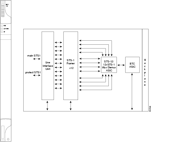
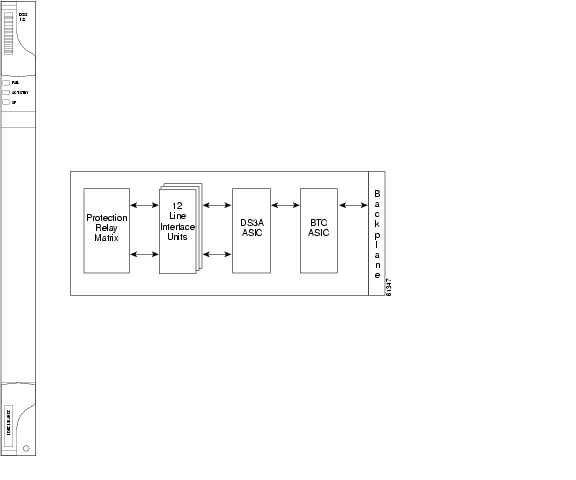
The EC1-12 card provides 12 Telcordia-compliant, GR-253 STS-1 electrical ports per card. Each port operates at 51.840 Mbps over a single 75-ohm, 728A or equivalent coaxial span.
STS path selection for UNEQ-P, AIS-P, and bit error rate (BER) thresholds is done on the SONET ring interfaces (optical cards) in conjunction with the STS cross-connect. The EC1-12 terminates but does not select the 12 working STS-1 signals from the backplane. The EC1-12 maps each of the 12 received EC1 signals into 12 STS-1s with visibility into the SONET path overhead.
An EC1-12 card can be 1:1 protected with another EC1-12 card but cannot protect more than one EC1-12 card. You must install the EC1-12 in an even-numbered slot to serve as a working card and in an odd-numbered slot to serve as a protect card.
3.2.1 EC1-12 Slots and Connectors
You can install the EC1-12 card in Slots 1 to 6 or 12 to 17 on the ONS 15454. Each EC1-12 interface features DSX-level (digital signal cross-connect frame) outputs supporting distances up to 450 feet (137 meters) depending on facility conditions. See the "7.2 Electrical Card Protection and the Backplane" section on page 7-5 for more information about electrical card slot protection and restrictions.
3.2.2 EC1-12 Faceplate and Block Diagram
Figure 3-1 shows the EC1-12 faceplate and a block diagram of the card.
Figure 3-1 EC1-12 Faceplate and Block Diagram
3.2.3 EC1-12 Hosted by XCVT, XC10G, or XC-VXC-10G
All 12 STS-1 payloads from an EC1-12 card are carried to the XCVT, XC10G, or XC-VXC-10G card where the payload is further aggregated for efficient transport. XCVT cards can host a maximum of 288 bidirectional STS-1s. The XC10G and XC-VXC-10G cards can host up to 1152 bidirectional STS-1s.
3.2.4 EC1-12 Card-Level Indicators
Table 3-3 describes the three card-level LEDs on the EC1-12 card.
3.2.5 EC1-12 Port-Level Indicators
You can obtain the status of the EC1-12 card ports by using the LCD screen on the ONS 15454 fan tray. Use the LCD to view the status of any port or card slot; the screen displays the number and severity of alarms for a given port or slot.
3.3 DS1-14 and DS1N-14 Cards
Note
The ONS 15454 DS1-14 card provides 14 Telcordia-compliant, GR-499 DS-1 ports. Each port operates at 1.544 Mbps over a 100-ohm, twisted-pair copper cable. The DS1-14 card can function as a working or protect card in 1:1 protection schemes and as a working card in 1:N protection schemes. Each DS1-14 port has digital signal cross-connect frame (DSX)-level outputs supporting distances up to 655 feet (200 meters).
The DS1-14 card supports 1:1 protection. The DS1-14 can be a working card in a 1:N protection scheme with the proper backplane EIA and wire-wrap or AMP Champ connectors. You can also provision the DS1-14 to monitor for line and frame errors in both directions.
You can group and map DS1-14 card traffic in STS-1 increments to any other card in an ONS 15454 except DS-3 cards. Each DS-1 is asynchronously mapped into a SONET VT1.5 payload and the card carries a DS-1 payload intact in a VT1.5. For performance monitoring purposes, you can gather bidirectional DS-1 frame-level information (LOF, parity errors, cyclic redundancy check [CRC] errors, and so on).
3.3.1 DS1N-14 Features and Functions
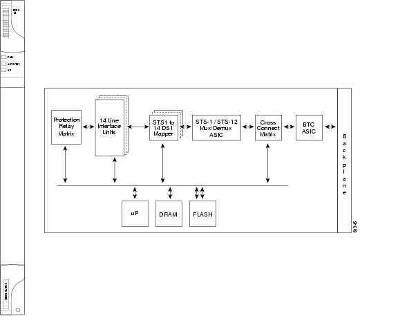
The DS1N-14 card supports the same features as the DS1-14 card in addition to enhanced protection schemes. The DS1N-14 is capable of 1:N (N <= 5) protection with the proper backplane EIA and wire-wrap or AMP Champ connectors. The DS1N-14 card can function as a working or protect card in 1:1 or 1:N protection schemes.
If you use the DS1N-14 as a standard DS-1 card in a 1:1 protection group, you can install the DS1N-14 card in Slots 1 to 6 or 12 to 17 on the ONS 15454. If you use the card's 1:N functionality, you must install a DS1N-14 card in Slots 3 and 15. Each DS1N-14 port features DS-n-level outputs supporting distances of up to 655 feet (200 meters) depending on facility conditions.
3.3.2 DS1-14 and DS1N-14 Slot Compatibility
You can install the DS1-14 card in Slots 1 to 6 or 12 to 17 on the ONS 15454.
3.3.3 DS1-14 and DS1N-14 Faceplate and Block Diagram
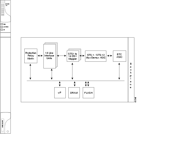
Figure 3-2 shows the DS1-14 faceplate and the block diagram of the card.
Figure 3-2 DS1-14 Faceplate and Block Diagram
Figure 3-3 shows the DS1N-14 faceplate and a block diagram of the card.
Figure 3-3 DS1N-14 Faceplate and Block Diagram
3.3.4 DS1-14 and DS1N-14 Hosted by XCVT, XC10G, or XC-VXC-10G
All 14 VT1.5 payloads from DS1-14 and DSIN-14 cards are carried in a single STS-1 to the XCVT, XC10G, or XC-VXC-10G cards, where the payload is further aggregated for efficient STS-1 transport. The XC10G and XCVT cards manage up to 336 bidirectional VT1.5 ports. The XC-VXC-10G card can manage up to 2688 bidirectional VT1.5 ports
3.3.5 DS1-14 and DS1N-14 Card-Level Indicators
Table 3-4 describes the three card-level LEDs on the DS1-14 and DS1N-14 card faceplates.
3.3.6 DS1-14 and DS1N-14 Port-Level Indicators
You can obtain the status of the DS1-14 and DS1N-14 card ports by using the LCD screen on the ONS 15454 fan-tray assembly. Use the LCD to view the status of any port or card slot; the screen displays the number and severity of alarms for a given port or slot.
3.4 DS1/E1-56 Card
Note
The ONS 15454 DS1/E1-56 card provides 56 Telcordia-compliant, GR-499 DS-1 ports per card, or 56 E1 ports per card. Each port operates at 1.544 Mbps (DS-1) or 2.048 Mbps (E1). The DS1/E1-56 card operates as a working or protect card in 1:N protection schemes, where N <= 2. The DS1/E1-56 card can be used with the XCVT, XC10G, or XC-VXC-10G cross-connect cards.
Note
Caution
3.4.1 DS1/E1-56 Slots and Connectors
For SONET applications, the DS1/E1-56 card requires a high-density (HD) shelf (15454-SA-HD), UBIC EIA, and Software Release 6.0 or greater.
Note
Note
You can install the DS1/E1-56 card in Slots 1 to 3 or 15 to 17 on the ONS 15454, but installing this card in certain slots will block the use of other slots. Table 3-5 shows which slots become unusable for other electrical cards when the DS1/E1-56 card is installed in a particular slot.
With the proper backplane EIA, the card supports SCSI (UBIC) connectors. See the "7.2 Electrical Card Protection and the Backplane" section on page 7-5 for more information about electrical card slot protection and restrictions.
3.4.2 DS1/E1-56 Faceplate and Block Diagram
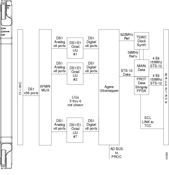
Figure 3-4 shows the DS1/E1-56 faceplate and a block diagram of the card.
Figure 3-4 DS1/E1-56 Faceplate and Block Diagram
3.4.3 DS1/E1-56 Card-Level Indicators
The DS1/E1-56 card has three card-level LED indicators ( Table 3-6).
3.4.4 DS1/E1-56 Port-Level Indicators
You can obtain the status of the DS1/E1-56 card ports by using the LCD screen on the ONS 15454 fan-tray assembly. Use the LCD to view the status of any port or card slot; the screen displays the number and severity of alarms for a given port or slot.
3.5 DS3-12 and DS3N-12 Cards
Note
Note
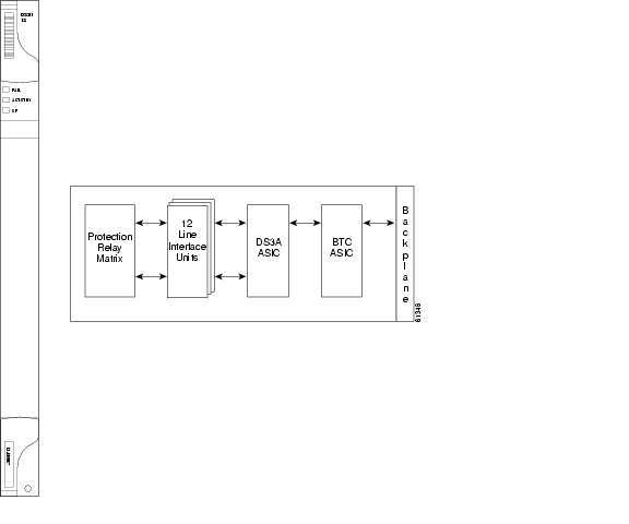
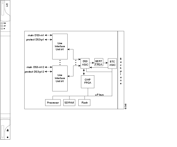
The ONS 15454 DS3-12 card provides 12 Telcordia-compliant, GR-499 DS-3 ports per card. Each port operates at 44.736 Mbps over a single 75-ohm 728A or equivalent coaxial span. The DS3-12 card operates as a working or protect card in 1:1 protection schemes and as a working card in 1:N protection schemes.
The DS3-12 card supports 1:1 protection with the proper backplane EIA. EIAs are available with BNC, SMB, or SCSI (UBIC) connectors.
Caution
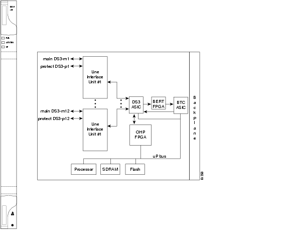
Other than protection capabilities, the DS3-12 and DS3N-12 cards are identical. The DS3N-12 can operate as the protect card in a 1:N (N <= 5) DS3 protection group. It has additional circuitry that is not present on the basic DS3-12 card that allows it to protect up to five working DS3-12 cards. The basic DS3-12 card can only function as the protect card for one other DS3-12 card.
3.5.1 DS3-12 and DS3N-12 Slots and Connectors
You can install the DS3-12 or DS3N-12 card in Slots 1 to 6 or 12 to 17 on the ONS 15454. Each DS3-12 or DS3N-12 card port features DSX-level outputs supporting distances up to 137 meters (450 feet) depending on facility conditions. With the proper backplane EIA, the card supports BNC or SMB connectors. See the "7.2 Electrical Card Protection and the Backplane" section on page 7-5 for more information about electrical card slot protection and restrictions.
3.5.2 DS3-12 and DS3N-12 Faceplate and Block Diagram
Figure 3-5 shows the DS3-12 faceplate and a block diagram of the card.
Figure 3-5 DS3-12 Faceplate and Block Diagram
Figure 3-6 shows the DS3N-12 faceplate and a block diagram of the card.
Figure 3-6 DS3N-12 Faceplate and Block Diagram
3.5.3 DS3-12 and DS3N-12 Card-Level Indicators
Table 3-7 describes the three card-level LEDs on the DS3-12 and DS3N-12 card faceplates.
3.5.4 DS3-12 and DS3N-12 Port-Level Indicators
You can find the status of the 12 DS3-12 and 12 DS3N-12 card ports by using the LCD screen on the ONS 15454 fan-tray assembly. Use the LCD to view the status of any port or card slot; the screen displays the number and severity of alarms for a given port or slot.
3.6 DS3/EC1-48 Card
Note
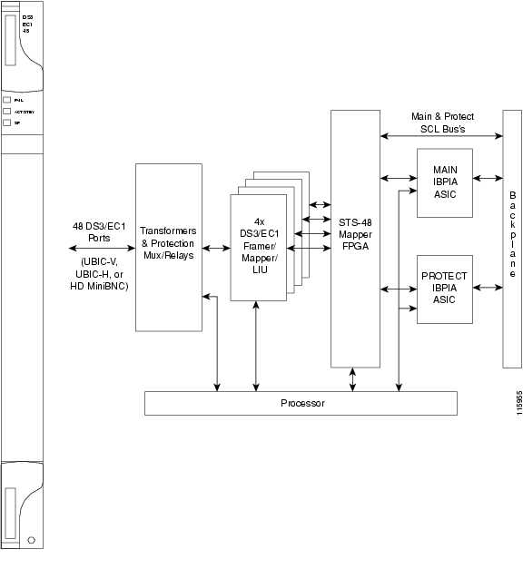
The ONS 15454 DS3/EC1-48 card provides 48 Telcordia-compliant, GR-499 DS-3 ports per card. Each port operates at 44.736 Mbps over a single 75-ohm 728A or equivalent coaxial span. The DS3/EC1-48 card operates as a working or protect card in 1:N protection schemes, where N <= 2.
Caution
3.6.1 DS3/EC1-48 Slots and Connectors
For SONET applications, the DS3/EC1-48 card requires an HD shelf (15454-SA-HD) and EIA (UBIC, MiniBNC); Software Release 5.0 or greater; and XC10G or XC-VXC-10G cards.
Note
You can install the DS3/EC1-48 card in Slots 1 to 3 or 15 to 17 on the ONS 15454, but installing this card in certain slots will block the use of other slots. Table 3-8 shows which slots become unusable for other electrical cards when the DS3/EC1-48 card is installed in a particular slot.
Caution
Caution
With the proper backplane EIA, the card supports BNC or SCSI (UBIC) connectors. See the "7.2 Electrical Card Protection and the Backplane" section on page 7-5 for more information about electrical card slot protection and restrictions.
3.6.2 DS3/EC1-48 Faceplate and Block Diagram
Figure 3-7 shows the DS3/EC1-48 faceplate and a block diagram of the card.
Figure 3-7 DS3/EC1-48 Faceplate and Block Diagram
3.6.3 DS3/EC1-48 Card-Level Indicators
The DS3/EC1-48 card has three card-level LED indicators ( Table 3-9).
3.6.4 DS3/EC1-48 Port-Level Indicators
You can obtain the status of the DS3/EC1-48 card ports by using the LCD screen on the ONS 15454 fan-tray assembly. Use the LCD to view the status of any port or card slot; the screen displays the number and severity of alarms for a given port or slot.
3.7 DS3i-N-12 Card
Note
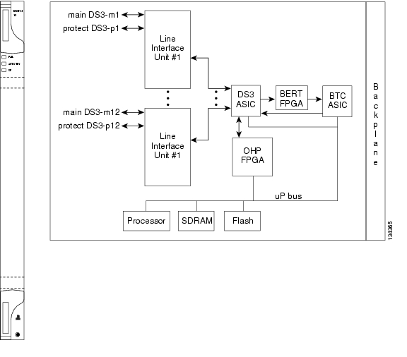
The 12-port ONS 15454 DS3i-N-12 card provides 12 ITU-T G.703, ITU-T G.704, and Telcordia GR-499-CORE compliant DS-3 ports per card. Each port operates at 44.736 Mbps over a 75-ohm coaxial cable. The DS3i-N-12 card supports 1:1 or 1:N protection with the proper backplane EIA. The DS3i-N-12 card works with the XCVT, XC10G, and XC-VXC-10G cross-connect cards. Four sets of three adjacent DS-3 signals (Port 1 through Port 3, Port 4 through Port 6, Port 7 through Port 9, and Port 10 through Port 12) are mapped to VC3s into a VC4 and transported as an STC-3c.
The DS3i-N-12 can also aggregate DS3 and E1 traffic and transport it between SONET and SDH networks through AU4/STS 3 trunks, with the ability to add and drop DS3s to an STS3 trunk at intermediate nodes.
3.7.1 DS3i-N-12 Slots and Connectors
You can install the DS3i-N-12 card in Slots 1 to 6 and 12 to 17. The DS3i-N-12 can operate as the protect card in a 1:N (N <= 5) DS-3 protection group on a half-shelf basis, with protection cards in Slots 3 and 15. It has circuitry that allows it to protect up to five working DS3i-N-12 cards. With the proper backplane EIA, the card supports BNC or SMB connectors. See the "7.2 Electrical Card Protection and the Backplane" section on page 7-5 for more information about electrical card slot protection and restrictions.
Figure 3-8 shows the DS3i-N-12 faceplate and block diagram.
Figure 3-8 DS3i-N-12 Faceplate and Block Diagram
The following list summarizes the DS3i-N-12 card features:
•
•
•
•
•
•
•
•
•
•
•
•
3.7.2 DS3i-N-12 Card-Level Indicators
Table 3-10 describes the three LEDs on the DS3i-N-12 card faceplate.
3.7.3 DS3i-N-12 Port-Level Indicators
You can find the status of the DS3i-N-12 card ports by using the LCD screen on the ONS 15454 fan-tray assembly. Use the LCD to view the status of any port or card slot; the screen displays the number and severity of alarms for a given port or slot. Refer to the Cisco ONS 15454 Troubleshooting Guide for a complete description of the alarm messages.
3.8 DS3-12E and DS3N-12E Cards
Note
The ONS 15454 DS3-12E card provides 12 Telcordia-compliant GR-499 DS-3 ports per card. Each port operates at 44.736 Mbps over a single 75-ohm 728A or equivalent coaxial span. The DS3-12E card provides enhanced performance monitoring functions. The DS3-12E can detect several different errored logic bits within a DS3 frame. This function allows the ONS 15454 to identify a degrading DS3 facility caused by upstream electronics (DS3 Framer). In addition, DS3 frame format autodetection and J1 path trace are supported. By monitoring additional overhead in the DS3 frame, subtle network degradations can be detected.
The following list summarizes DS3-12E card features:
•
•
•
•
•
•
•
•
•
•
The DS3-12E supports a 1:1 protection scheme, meaning it can operate as the protect card for one other DS3-12E card.
The DS3N-12E can operate as the protect card in a 1:N (N <= 5) DS3 protection group. It has additional circuitry not present on the basic DS3-12E card that allows it to protect up to five working DS3-12E cards. The basic DS3-12E card can only function as the protect card for one other DS3-12E card.
3.8.1 DS3-12E and DS3N-12E Slots and Connectors
You can install the DS3-12E and DS3N-12E cards in Slots 1 to 6 or 12 to 17 on the ONS 15454. Each DS3-12E and DS3N-12E port features DSX-level outputs supporting distances up to 137 meters (450 feet). With the proper backplane EIA, the card supports BNC or SMB connectors. See the "7.2 Electrical Card Protection and the Backplane" section on page 7-5 for more information about electrical card slot protection and restrictions.
3.8.2 DS3-12E Faceplate and Block Diagram
Figure 3-9 shows the DS3-12E faceplate and a block diagram of the card.
Figure 3-9 DS3-12E Faceplate and Block Diagram
Figure 3-10 shows the DS3N-12E faceplate and a block diagram of the card.
Figure 3-10 DS3N-12E Faceplate and Block Diagram
3.8.3 DS3-12E and DS3N-12E Card-Level Indicators
Table 3-11 describes the three card-level LEDs on the DS3-12E and DS3N-12E card faceplates.
3.8.4 DS3-12E and DS3N-12E Port-Level Indicators
You can find the status of the DS3-12E and DS3N-12E card ports by using the LCD screen on the ONS 15454 fan-tray assembly. Use the LCD to quickly view the status of any port or card slot; the screen displays the number and severity of alarms for a given port or slot.
3.9 DS3XM-6 Card
Note
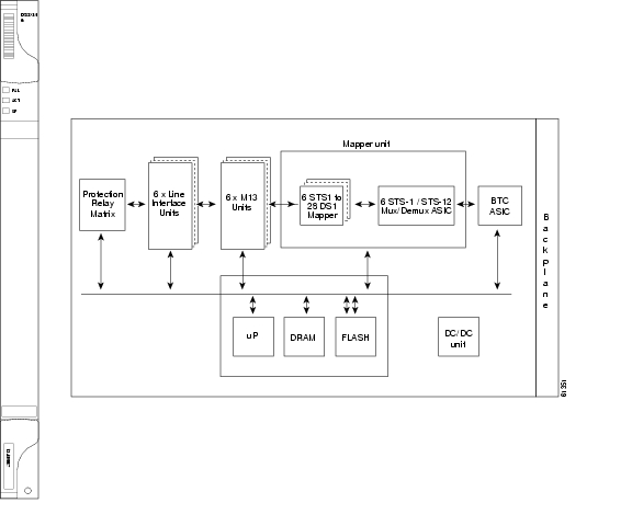
The DS3XM-6 card, commonly referred to as a transmux card, provides six Telcordia-compliant, GR-499-CORE M13 multiplexing ports. The DS3XM-6 converts six framed DS-3 network connections to 28 x6 or 168 VT1.5s. DS3XM-6 cards operate at the VT1.5 level.
3.9.1 DS3XM-6 Slots and Connectors
The DS3XM-6 card supports 1:1 protection with the proper backplane EIA. EIAs are available with BNC or SMB connectors.
You can install the DS3XM-6 in Slots 1 to 6 or 12 to 17. Each DS3XM-6 port features DSX-level outputs supporting distances up to 137 meters (450 feet) depending on facility conditions. See "7.2 Electrical Card Protection and the Backplane" section on page 7-5 for more information about electrical card slot protection and restrictions.
3.9.2 DS3XM-6 Faceplate and Block Diagram
Figure 3-11 shows the DS3XM-6 faceplate and a block diagram of the card.
Figure 3-11 DS3XM-6 Faceplate and Block Diagram
3.9.3 DS3XM-6 Hosted By XCVT, XC10G, XC-VXC-10G
The DS3XM-6 card works in conjunction with the XCVT, XC10G, XC-VXC-10G card. A single DS3XM-6 can demultiplex six DS-3 signals into 168 VT1.5s that the XCVT card then manages and cross connects. XCVT cards host a maximum of 336 bidirectional VT1.5s on two DS3XM-6 cards. In most network configurations, two DS3XM-6 cards are paired together as working and protect cards.
3.9.4 DS3XM-6 Card-Level Indicators
Table 3-12 describes the three card-level LEDs on the DS3XM-6 card faceplate.
3.9.5 DS3XM-6 Port-Level Indicators
You can find the status of the six DS3XM-6 card ports by using the LCD screen on the ONS 15454 fan-tray assembly. Use the LCD to quickly view the status of any port or card slot; the screen displays the number and severity of alarms for a given port or slot.
3.10 DS3XM-12 Card
Note
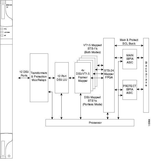
The DS3XM-12 card, commonly referred to as a transmux card, provides twelve Telcordia-compliant, GR-499-CORE M13 multiplexing ports. The DS3XM-12 converts up to 12 framed DS-3 network connections to 12 x 28 VT1.5s.
3.10.1 Backplane Configurations
The DS3XM-12 card has 12 framed DS-3 physical ports (known as "ported" mode). The card also supports a maximum of 12 "portless" DS3-mapped STS1 interfaces depending on the type of cross-connect used. Each physical port corresponds to two portless ports. If a circuit is provisioned to a physical port, its associated portless pair becomes unavailable and vice versa. See the "11.4 Portless Transmux" section on page 11-15 for more information.
The DS3XM-12 card is compatible with the XCVT, XC10G, and XC-VXC-10G cross-connect cards.
Note
The DS3XM-12 supports three different backplane throughput configurations:
•
•
•
The backplane throughput configuration is selected in CTC card view using the Maintenance > Card tab.
3.10.2 Ported Mode
The "ported" mode supports up to 12 framed DS-3 bidirectional mapped signals to each DS3XM-12 card, where the traffic is demultiplexed and mapped into a VT1.5 payload. This payload is then mapped and multiplexed up to a bidirectional STS-1.
3.10.3 Portless Mode
The "portless" mode allows for IXC hand off connections through a standard SONET fiber optical interface with DS-3-mapped STS-1s as a payload. This physical connection is accomplished with any of the OC-N cards. The system cross-connect grooms the DS-3 mapped STS1 traffic to the appropriate DS3XM-12 card, where the traffic is demultiplexed and mapped into a VT1.5 payload. This payload is then mapped and multiplexed up to a higher rate STS-1. See the "11.4 Portless Transmux" section on page 11-15 for more information.
3.10.4 Shelf Configurations
The DS3XM-12 card supports the XCVT, XC10G, and XC-VXC-10G cards. The DS3XM-12 card is supported in any of the multiservice slots (Slots 1 through 6 and 12 through 17).
The DS3XM-12 card operates at the VT1.5 level and supports a maximum of 6 or 12 ports of "portless" (DS-3-mapped STS1s) interface, depending on the shelf configuration (see Table 3-13).
Caution
3.10.5 Protection Modes
The DS3XM-12 card supports 1:1 and 1:N protection groups, where N <= 5. However, N <= 7 if one of the following conditions is true:
•
•
These protection groups can be implemented in the ONS 15454 SONET platform for both the A and B sides and do not require a special protect card.
In 1:N protection, the protect card must be in Slot 3 or 15. In 1:1 protection, the working and protect cards must be in adjacent slots. The protection switches cause a traffic hit of no more than 50 ms. See the "7.2 Electrical Card Protection and the Backplane" section on page 7-5 for more information about electrical card slot protection and restrictions.
3.10.6 Card Features
Table 3-14 summarizes the DS3XM-12 features.
3.10.7 DS3XM-12 Slots and Connectors
The DS3XM-12 card can be used with BNC, SMB, SCSI (UBIC), or MiniBNC EIA connectors.
The card can be installed in Slots 1 to 6 or 12 to 17. Each DS3XM-12 port features DSX-level outputs supporting distances up to 137 meters (450 feet) depending on facility conditions.
3.10.8 DS3XM-12 Faceplate and Block Diagram
Figure 3-12 shows the DS3XM-12 faceplate and a block diagram of the card.
Figure 3-12 DS3XM-12 Faceplate and Block Diagram
3.10.9 DS3XM-12 Card-Level Indicators
Table 3-15 describes the three card-level LEDs on the DS3XM-12 card faceplate.
3.10.10 DS3XM-12 Port-Level Indicators
You can find the status of the twelve DS3XM-12 card ports by using the LCD screen on the ONS 15454 fan-tray assembly. Use the LCD to quickly view the status of any port or card slot; the screen displays the number and severity of alarms for a given port or slot.
![]()
![]()
![]()
![]()
![]()
![]()
![]()
![]()
Posted: Wed Sep 5 06:38:36 PDT 2007
All contents are Copyright © 1992--2007 Cisco Systems, Inc. All rights reserved.
Important Notices and Privacy Statement.