|
|

Table Of Contents
Install the Shelf and Common Control Cards
Required Tools and Equipment (ANSI)
Cisco-Supplied Materials (ANSI)
User-Supplied Materials (ANSI)
Required Tools and Equipment (ETSI)
Cisco-Supplied Equipment (ETSI)
User-Supplied Equipment (ETSI)
NTP-G1 Unpack and Inspect the Shelf Assembly
DLP-G1 Unpack and Verify the Shelf Assembly
DLP-G2 Inspect the Shelf Assembly
NTP-G2 Install the Shelf Assembly
DLP-G3 Reverse the Mounting Bracket to Fit a 19-inch (482.6-mm) Rack (ANSI Only)
DLP-G4 Install the External Brackets and Air Filter (ANSI Only)
DLP-G5 Mount the Shelf Assembly in a Rack (One Person)
DLP-G6 Mount the Shelf Assembly in a Rack (Two People)
DLP-G7 Mount Multiple Shelf Assemblies in a Rack
NTP-G3 Open and Remove the Front Door
DLP-G9 Open the Front Cabinet Compartment (Door)
NTP-G4 Open and Remove the FMEC Cover (ETSI Only)
NTP-G5 Remove the Backplane Covers (ANSI Only)
DLP-G13 Remove the Lower Backplane Cover
DLP-G14 Remove the Backplane Sheet Metal Cover
NTP-G6 Install the MIC-A/P and MIC-T/C/P FMECs (ETSI Only)
NTP-G7 Install the Power and Ground
DLP-G15 Connect the Office Ground to the ONS 15454 ETSI
DLP-G16 Connect the Office Ground to the ONS 15454 ANSI
DLP-G17 Connect Office Power to the ONS 15454 ETSI
DLP-G18 Connect Office Power to the ONS 15454 ANSI
DLP-G19 Turn On and Verify Office Power
NTP-G8 Install the Fan-Tray Assembly
NTP-G9 Install the Alarm Expansion Panel (ANSI Only)
NTP-G10 Attach Wires to Alarm, Timing, LAN, and Craft Pin Connections
DLP-G20 Install Alarm Wires on the MIC-A/P (ETSI Only)
DLP-G21 Install Timing Wires on the MIC-C/T/P (ETSI Only)
DLP-G22 Install LAN Wires on the MIC-C/T/P (ETSI Only)
DLP-G23 Install Alarm Wires on the Backplane (ANSI Only)
DLP-G24 Install Timing Wires on the Backplane (ANSI Only)
DLP-G25 Install LAN Wires on the Backplane (ANSI Only)
DLP-G26 Install the TL1 Craft Interface Wires (ANSI Only)
NTP-G11 Install an External Wire-Wrap Panel on the AEP (ANSI Only)
NTP-G12 Install and Close the FMEC Cover (ETSI Only)
NTP-G13 Install the Rear Cover (ANSI Only)
NTP-G14 Install DWDM Equipment
DLP-G27 Install the DCU Shelf Assembly
DLP-G28 Install the Fiber Patch-Panel Tray
DLP-G29 Install the Fiber-Storage Tray
DLP-G371 Install the Ethernet Adapter Panel
DLP-G351 Install the Y-Cable Module Tray
DLP-G30 Install the FlexLayer Shelf
DLP-G31 Install the FlexLayer Modules
DLP-G32 Install the Y-Cable Protection Modules in the FlexLayer Shelf
DLP-G377 Install the Y-Cable Protection Modules in the Y-Cable Module Tray
NTP-G15 Install the Common Control Cards
DLP-G33 Install the TCC2 or TCC2P Card
DLP-G34 Install the AIC-I Card
DLP-G309 Install the MS-ISC-100T Card
NTP-G145 Connect a Multishelf Node and Subtending Shelves to an MS-ISC-100T Card
NTP-G158 Connect a Multishelf Node and Subtending Shelves to a Cisco Catalyst 2950
NTP-G159 Configure a Cisco Catalyst 2950 for a Multishelf Node
NTP-G16 Perform the Shelf Installation Acceptance Test
DLP-G35 Inspect the Shelf Installation and Connections
Install the Shelf and Common Control Cards
This chapter explains how to install the Cisco ONS 15454 ETSI and Cisco ONS 15454 ANSI shelf assemblies. Where procedures differ for the two shelf types, the procedure will indicate "ANSI only" or "ETSI only." For a summary of the tools and equipment required for installation, see the "Required Tools and Equipment (ETSI)" section or the "Required Tools and Equipment (ANSI)" section.
Note
Unless otherwise specified, "ONS 15454" refers to both ANSI and ETSI shelf assemblies.
Before You Begin
This section lists the chapter procedures (NTPs). Turn to a procedure for applicable tasks (DLPs). Read the installation procedures and precautions before you install the ONS 15454 ANSI or ONS 15454 ETSI and connect the power source.
1.
2.
3.
4.
5.
6.
7.
8.
9.
10.
11.
12.
13.
14.
15.
16.
17.
18.
19.
Warning
Warning
Warning
Warning
Warning
Warning
Note
Note
Required Tools and Equipment (ANSI)
You need the following tools and equipment to install and test the ONS 15454 ANSI shelf assembly.
Cisco-Supplied Materials (ANSI)
The following materials are required and are shipped with the ONS 15454 ANSI shelf (wrapped in plastic). The number in parentheses gives the quantity of the item included in the package.
•
•
•
•
•
•
•
•
•
•
•
–
–
User-Supplied Materials (ANSI)
The following materials and tools are required but are not supplied with the ONS 15454 ANSI:
•
–
–
•
•
•
•
•
•
•
•
•
•
•
•
#10 AWG copper conductorsTools Needed (ANSI)
The following tools are needed to install an ONS 15454 ANSI:
•
•
•
•
•
•
•
•
Test Equipment (ANSI)
The following test equipment is needed to install an ONS 15454 ANSI:
•
•
•
Required Tools and Equipment (ETSI)
You need the following tools and equipment to install and test the ONS 15454 ETSI shelf assembly.
Cisco-Supplied Equipment (ETSI)
These materials are required for installation and are supplied with the ONS 15454 ETSI. The shipped quantity of each item is in parentheses.
•
•
•
•
•
•
•
•
•
•
•
Caution
User-Supplied Equipment (ETSI)
The following materials and tools are required for installation but are not supplied with the ONS 15454 ETSI:
•
•
•
•
•
•
•
•
•
Note
Tools Needed (ETSI)
To install the ONS 15454 ETSI, you need the following tools.
•
•
•
•
•
•
•
Test Equipment (ETSI)
To install the ONS 15454 ETSI, you need the following test equipment.
•
•
•
NTP-G1 Unpack and Inspect the Shelf Assembly
Step 1
Step 2
Step 3
Stop. You have completed this procedure.
DLP-G1 Unpack and Verify the Shelf Assembly
Purpose
This task removes the shelf assembly from the package.
Tools/Equipment
None
Prerequisite Procedures
None
Required/As Needed
Required
Onsite/Remote
Onsite
Security Level
None
Step 1
Step 2
Step 3
Step 4
Note
Step 5
DLP-G2 Inspect the Shelf Assembly
Step 1
Step 2
•
•
Step 3
Step 4
Step 5
NTP-G2 Install the Shelf Assembly
Warning
Warning
Warning
Warning
Warning
Warning
Note
Step 1
Step 2
Step 3
•
•
•
Step 4
Stop. You have completed this procedure.
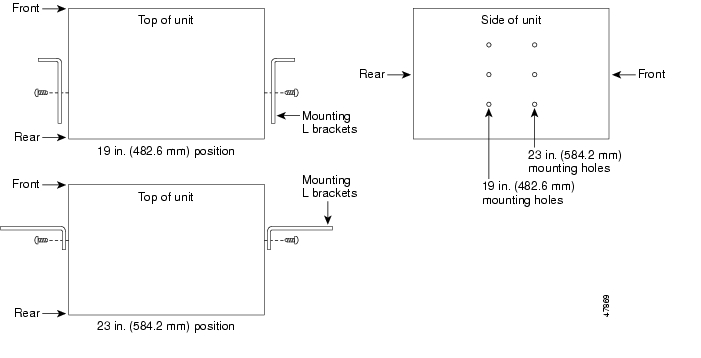
DLP-G3 Reverse the Mounting Bracket to Fit a 19-inch (482.6-mm) Rack (ANSI Only)
Caution
Caution
Step 1
Step 2
Text imprinted on the mounting bracket will now also be upside down.
Step 3
The narrow side of the mounting bracket should be towards the front of the shelf assembly. Text imprinted on the mounting bracket should be visible and upside down.
Step 4
Step 5
Step 6
Figure 1-1 Reversing the Mounting Brackets (23-inch [584.2-mm] Position to 19-inch [482.6-mm] Position
Step 7
DLP-G4 Install the External Brackets and Air Filter (ANSI Only)
Purpose
This task installs the external brackets and air filter on the bottom of the shelf rather than below the fan-tray assembly. Installing the external brackets and air filter on the bottom of the shelf enables access to the air filter without removing the fan-tray assembly. This task applies to the ONS 15454 ANSI shelf only.
Tools/Equipment
#2 Phillips screwdriver
Medium slot-head screwdriver
Small slot-head screwdriver
Prerequisite Procedures
G3 Reverse the Mounting Bracket to Fit a 19-inch (482.6-mm) Rack (ANSI Only), if applicable
Required/As Needed
As needed
Onsite/Remote
Onsite
Security Level
None
Note
Step 1
Note
Step 2
Step 3
Each bracket has a filter stopper and a flange on one end. Make sure to attach the brackets with the stoppers and flanges facing the rear of the shelf assembly (the top, if the ONS 15454 is facedown during installation).
Figure 1-2 illustrates bottom bracket installation. If you do not use the brackets, in the future you must remove the fan-tray assembly before removing the air filter. The brackets enable you to clean and replace the air filter without removing the fan-tray assembly.
Figure 1-2 Installing the External Brackets
Step 4
Step 5
DLP-G5 Mount the Shelf Assembly in a Rack (One Person)
Note
Step 1
•
•
•
Step 2
Figure 1-3 shows the rack-mounting position for the ONS 15454 ETSI.
Figure 1-3 Mounting an ONS 15454 ETSI in a Rack
Step 3
Step 4
Step 5
Step 6
Step 7
Note
Step 8
Step 9
DLP-G6 Mount the Shelf Assembly in a Rack (Two People)
Note
Note
Step 1
•
•
•
Step 2
Step 3
Step 4
Step 5
Step 6
Step 7
Note
Step 8
Step 9
DLP-G7 Mount Multiple Shelf Assemblies in a Rack
Note
Note
Note
Step 1
•
•
•
Step 2
Figure 1-4 shows a three-shelf ONS 15454 ETSI bay assembly.
Figure 1-4 Three-Shelf ONS 15454 ETSI (15454 SDH) Bay Assembly
Step 3
The air ramp is needed if you install more than one ONS 15454 ETSI shelf in a rack. To ensure that the air ramp is secure, use one or two M6 mounting screws for each side of the shelf assembly. Figure 1-5 shows how to mount an air ramp in the rack.
Figure 1-5 Mounting the Air Ramp in a Rack
Step 4
Step 5
DLP-G8 Install the Air Ramp
Purpose
Use this task to install the air ramp.
Tools/Equipment
#2 Phillips screwdriver
Prerequisite Procedures
None
Required/As Needed
As needed
Onsite/Remote
Onsite
Security Level
None
Step 1
Step 2
Step 3
Step 4
NTP-G3 Open and Remove the Front Door
Step 1
Step 2
Step 3
Stop. You have completed this procedure.
DLP-G9 Open the Front Cabinet Compartment (Door)
Purpose
This task opens the front door.
Tools/Equipment
Pinned hex (Allen) key
Prerequisite Procedures
Required/As Needed
Required
Onsite/Remote
Onsite
Security Level
None
Note
Step 1
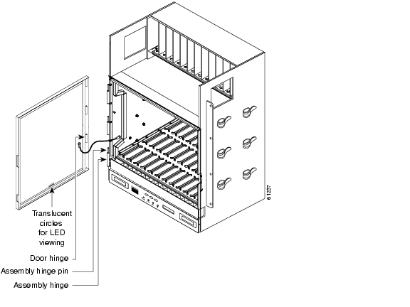
The ONS 15454 shelf assembly comes with a pinned hex key for locking and unlocking the front door. Turn the key counterclockwise to unlock the door and clockwise to lock it. Figure 1-6 illustrates the front door of the ANSI shelf.
Figure 1-6 Cisco ONS 15454 ANSI Front Door
Step 2
Step 3
Step 4
DLP-G10 Remove the Front Door
Purpose
This task removes the front cabinet compartment door.
Tools/Equipment
Open-end wrench
Prerequisite Procedures
Required/As Needed
As needed
Onsite/Remote
Onsite
Security Level
None
Step 1
a.
b.
c.
Figure 1-7 Removing the ONS 15454 ETSI Front Door
Step 2
a.
•
•
b.
Figure 1-8 Removing the ONS 15454 ANSI Front Door
Step 3
NTP-G4 Open and Remove the FMEC Cover (ETSI Only)
Step 1
Step 2
Step 3
Stop. You have completed this procedure.
DLP-G11 Open the FMEC Cover
Step 1
Figure 1-9 Unscrewing the FMEC Cover
Step 2
Step 3
DLP-G12 Remove the FMEC Cover
Step 1
Step 2
Step 3
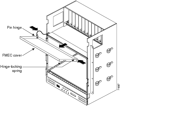
Figure 1-10 Removing the ONS 15454 FMEC Cover
Step 4
Step 5
Step 6
NTP-G5 Remove the Backplane Covers (ANSI Only)
Step 1
Step 2
Figure 1-11 shows the location of the backplane covers.
Figure 1-11 Backplane Covers on the 15454 ANSI Shelf
Step 3
Stop. You have completed this procedure.
DLP-G13 Remove the Lower Backplane Cover
Step 1
Figure 1-12 Lower Backplane Cover
Step 2
Step 3
Step 4
DLP-G14 Remove the Backplane Sheet Metal Cover
Step 1
Step 2
Step 3
Step 4
Step 5
NTP-G6 Install the MIC-A/P and MIC-T/C/P FMECs (ETSI Only)
Warning
Caution
Note
Step 1
•
The MIC-A/P card provides connection for the BATTERY B input, one of the two possible redundant power supply inputs. It also provides connection for eight alarm outputs (coming from the TCC2/TCC2P card), sixteen alarm inputs, and four configurable alarm inputs/outputs.
•
The MIC-C/T/P card provides connection for the BATTERY A input, one of the two possible redundant power supply inputs. It also provides connection for system management serial port, system management LAN port, and system timing inputs and outputs.
Step 2
Step 3
Step 4
Figure 1-13 Installing FMECs on the ONS 15454 ETSI
Step 5
Step 6
Stop. You have completed this procedure.
NTP-G7 Install the Power and Ground
Purpose
This procedure installs power feeds and grounds the ONS 15454.
Tools/Equipment
ANSI and ETSI:
•
•
•
•
•
•
•
•
•
•
ANSI only:
•
•
ETSI only:
•
•
Prerequisite Procedures
G4 Open and Remove the FMEC Cover (ETSI Only)
G6 Install the MIC-A/P and MIC-T/C/P FMECs (ETSI Only)
Required/As Needed
Required
Onsite/Remote
Onsite
Security Level
None
Warning
Warning
Warning
Warning
Warning
Warning
Warning
Caution
Step 1
•
•
•
Step 2
Step 3
Step 4
Step 5
Stop. You have completed this procedure.
DLP-G15 Connect the Office Ground to the ONS 15454 ETSI
Warning
Step 1
Step 2
Step 3
Step 4
Step 5
Step 6
Step 7
Step 8
Figure 1-14 Grounding the ONS 15454 ETSI
Step 9
DLP-G16 Connect the Office Ground to the ONS 15454 ANSI
Step 1
Step 2
Note
Figure 1-15 Ground Location on the Backplane
Step 3
Step 4
DLP-G17 Connect Office Power to the ONS 15454 ETSI
Warning
Caution
Note
Note
Caution
Note
Step 1
Step 2
Step 3
Step 4
Table 1-1 Pin Connection of the Power FMECs
A1
Battery return
Black
A2
-48 V battery
Red
A3
Ground
Green with yellow stripes
Step 5
DLP-G18 Connect Office Power to the ONS 15454 ANSI
Warning
Note
Note
Step 1
Step 2
Step 3
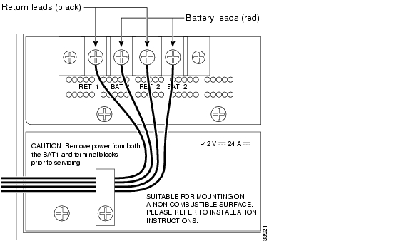
Figure 1-16 Cisco ONS 15454 Power Terminals
Step 4
Note
Caution
Caution
Step 5
Step 6
Note
Step 7
Step 8
Step 9
Step 10
Step 11
DLP-G19 Turn On and Verify Office Power
Purpose
This task measures the power to verify correct power and returns for the ONS 15454 shelf.
Tools/Equipment
Voltmeter
Prerequisite Procedures
G15 Connect the Office Ground to the ONS 15454 ETSI
G17 Connect Office Power to the ONS 15454 ETSI
G16 Connect the Office Ground to the ONS 15454 ANSI
Required/As Needed
Required
Onsite/Remote
Onsite
Security Level
None
Caution
Step 1
a.
Note
b.
Step 2
•
•
Step 3
Step 4
a.
Note
b.
Step 5
NTP-G8 Install the Fan-Tray Assembly
Purpose
This procedure installs the fan-tray assembly.
Tools/Equipment
#2 Phillips screwdriver
Medium slot-head screwdriver
Small slot-head screwdriver
Prerequisite Procedures
G3 Open and Remove the Front Door
Required/As Needed
Required
Onsite/Remote
Onsite
Security Level
None
Caution
Caution
Caution
Note
Note
Note
Step 1
Step 2
•
•
The electrical plug at the rear of the tray should plug into the corresponding receptacle on the assembly.
Caution
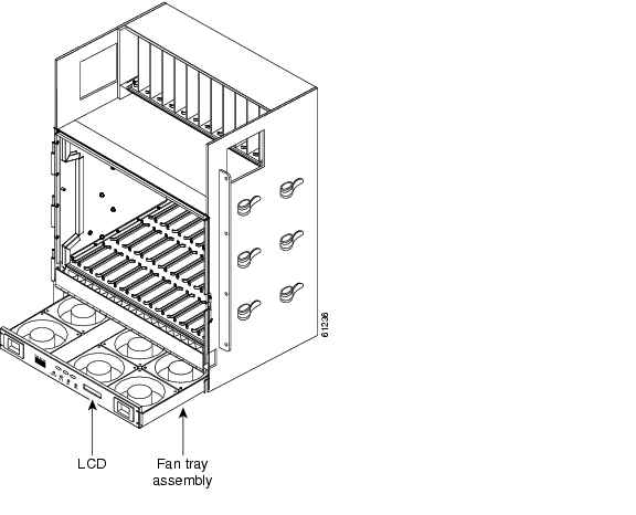
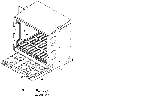
Figure 1-17 Installing the Fan-Tray Assembly on the ONS 15454 ETSI
Figure 1-18 Installing the Fan-Tray Assembly on the ONS 15454 ANSI
Step 3
Step 4
Stop. You have completed this procedure.
NTP-G9 Install the Alarm Expansion Panel (ANSI Only)
Note
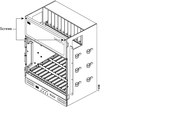
Step 1
Figure 1-19 Replace Backplane Screws with Standoffs
Step 2
Step 3
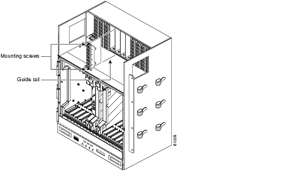
Figure 1-20 Installing Standoffs and the AEP
Step 4
Step 5
a.
b.
Figure 1-21 AEP Wire-Wrap Connections to Backplane Pins
Step 6
Stop. You have completed this procedure.
NTP-G10 Attach Wires to Alarm, Timing, LAN, and Craft Pin Connections
Purpose
This procedure installs alarm, timing, LAN, and craft wires on the ONS 15454 shelf. These wires are attached to the mechanical interface card (MIC) FMECs on the ETSI shelf and are attached to the backplane on the ANSI shelf.
Tools/Equipment
Connectors according to function
Twisted #22 or #24 AWG (0.51 mm≤ or 0.64 mm≤) shielded wires for LAN or craft
75-ohm coaxial cable with 1.0/2.3 miniature coax connector
0.51 mm≤ or 0.64 mm≤ (#22 or #24 AWG) alarm wires
Prerequisite Procedures
G6 Install the MIC-A/P and MIC-T/C/P FMECs (ETSI Only)
Required/As Needed
As needed
Onsite/Remote
Onsite
Security Level
None
Caution
Step 1
•
•
•
Step 2
•
•
•
•
Stop. You have completed this procedure.
DLP-G20 Install Alarm Wires on the MIC-A/P (ETSI Only)
Step 1
Step 2
Step 3
Step 4
Step 5
DLP-G21 Install Timing Wires on the MIC-C/T/P (ETSI Only)
Step 1
Step 2
The MIC-C/T/P provides 1.0/2.3 miniature coax connectors that are used for timing input and output. The top connectors are for "A" (BITS-1) timing, and the bottom connectors are for "B" (BITS-2) timing. In each case, the left connector is the input and the right connector is the output. The input connectors for timing provide a 75-ohm termination. System cables are available that can convert timing clocks from 75 ohms to 100/120 ohms. Table 1-4 shows MIC-C/T/P pin assignments.
Table 1-4 MIC-C/T/P Clock Connector Pin Assignment
IN 1
Input from external device
OUT 1
Output to external device
IN 2
Input from external device
OUT 2
Output to external device
A high-impedance option (> 3 kilo-ohms or greater) is possible through a jumper on the MIC-C/T/P FMEC. You can change the top timing input to high impedance by removing the jumper on P3 of the MIC-C/T/P FMEC. You can change the bottom timing input to high impedance by removing the jumper on P2 on the MIC-C/T/P FMEC.
Note
Step 3
Step 4
Step 5
DLP-G22 Install LAN Wires on the MIC-C/T/P (ETSI Only)
Note
Step 1
Table 1-5 LAN Pin Assignments
LAN 1
Connecting to DCE1
(a hub or switch)
Cross-over Ethernet cable1
3
PNMSRX+
white/green2
6
PNMSRX-
green3
1
PNMSTX
white/orange4
4
—
5
5
—
6
2
PNMSTX-
orange7
7
—
8
8
—
LAN 1
Connecting to DTE
(a PC/workstation or router)
Straight-through Ethernet cable1
1
PNMSRX+
white/green2
2
PNMSRX-
green3
3
PNMSTX+
white/orange4
4
—
5
5
—
6
6
PNMSTX-
orange7
7
—
8
8
—
1 The Cisco ONS 15454 ETSI is DCE.
Step 2
DLP-G23 Install Alarm Wires on the Backplane (ANSI Only)
Step 1
Figure 1-22 shows alarm pin assignments for the AIC-I in the Release 3.4 or higher ONS 15454 backplane, and Figure 1-23 calls out the external alarm pins on that backplane.
Figure 1-22 Cisco ONS 15454 Backplane Pinouts (Release 3.4 or Later)
Figure 1-23 Highlighted Environmental Alarms
Step 2
DLP-G24 Install Timing Wires on the Backplane (ANSI Only)
Step 1
Ground the shield of the BITS input cable at the BITS end. For BITS output, wrap the ground shield of the BITS cable to the frame ground pin (FG1) located beneath the column of BITS pins. Table 1-6 lists the pin assignments for the BITS timing pin fields.
Note
Step 2
DLP-G25 Install LAN Wires on the Backplane (ANSI Only)
Note
Step 1
Caution
A frame ground pin is located beneath each pin field (FG2 for the LAN pin field). Wrap the ground shield of the LAN interface cable to the frame ground pin. Table 1-7 shows the LAN pin assignments.
Note
Step 2
DLP-G26 Install the TL1 Craft Interface Wires (ANSI Only)
Note
Step 1
Step 2
Wrap the ground wire of your computer cable to pin A3 on the craft pin field. Table 1-8 shows the pin assignments for the CRAFT pin field.
Note
Table 1-8 Craft Interface Pin Assignments
Craft
A1
Receive
A2
Transmit
A3
Ground
A4
DTR
Step 3
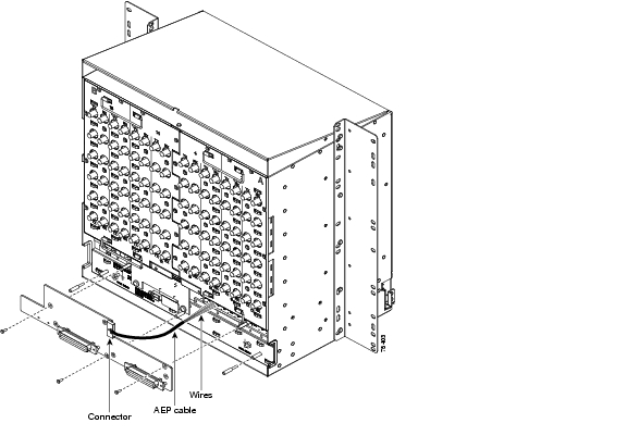
NTP-G11 Install an External Wire-Wrap Panel on the AEP (ANSI Only)
Step 1
Figure 1-24 Installing the AEP Cover
Step 2
Step 3
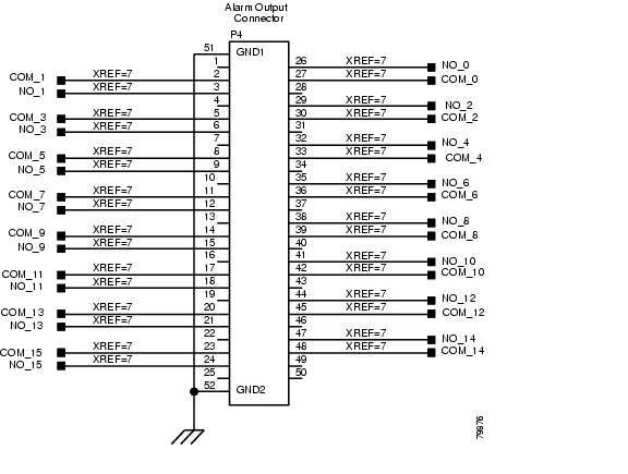
Table 1-10 lists the alarm output (external control) pin assignments.
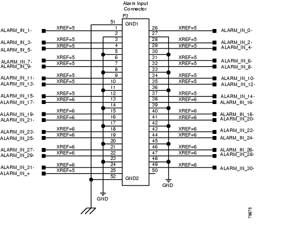
Figure 1-25 illustrates the alarm input connectors.
Figure 1-25 Alarm Input Connector
Figure 1-26 illustrates the alarm output connectors.
Figure 1-26 Alarm Output Connector
Step 4
Stop. You have completed this procedure.
NTP-G12 Install and Close the FMEC Cover (ETSI Only)
Step 1
Step 2
Step 3
Figure 1-27 ONS 15454 ETSI FMEC Cover
Step 4
Step 5
Step 6
Step 7
Stop. You have completed this procedure.
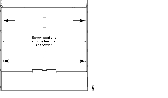
NTP-G13 Install the Rear Cover (ANSI Only)
Step 1
Figure 1-28 Backplane Attachment for the Rear Cover
Tip
Step 2
Step 3
Step 4
Step 5
Figure 1-29 shows rear cover installation using spacers.
Figure 1-29 Installing the Rear Cover with Spacers
Step 6
Stop. You have completed this procedure.
NTP-G14 Install DWDM Equipment
Step 1
Step 2
Step 3
Step 4
Step 5
Step 6
Note
Step 7
Step 8
Step 9
Stop. You have completed this procedure.
DLP-G27 Install the DCU Shelf Assembly
Step 1
Step 2
Step 3
Step 4
Step 5
DLP-G28 Install the Fiber Patch-Panel Tray
Step 1
Step 2
Step 3
Note
Step 4
DLP-G29 Install the Fiber-Storage Tray
Step 1
Step 2
Step 3
Step 4
DLP-G371 Install the Ethernet Adapter Panel
Step 1
Step 2
Step 3
Caution
Step 4
Step 5
DLP-G351 Install the Y-Cable Module Tray
Step 1
Step 2
Step 3
Step 4
DLP-G30 Install the FlexLayer Shelf
Step 1
Step 2
Step 3
Step 4
Step 5
Step 6
DLP-G31 Install the FlexLayer Modules
Step 1
Step 2
Note
Step 3
Figure 1-30 shows the FlexLayer shelf assembly and how the FlexLayer modules can be installed.
Figure 1-30 ONS 15xxx FlexLayer Shelf Assembly
Step 4
Step 5
DLP-G32 Install the Y-Cable Protection Modules in the FlexLayer Shelf
Step 1
Step 2
Step 3
Step 4
DLP-G377 Install the Y-Cable Protection Modules in the Y-Cable Module Tray
Step 1
Figure 1-31 Y-Cable Module
Step 2
Step 3
Step 4
Step 5
Step 6
NTP-G15 Install the Common Control Cards
Purpose
This procedure describes how to install the common control cards.
Tools/Equipment
Redundant TCC2/TCC2P cards (required)
AIC-I card (optional)
MS-ISC-100T (optional; for multishelf node configurations)
Prerequisite Procedures
G7 Install the Power and Ground
Required/As Needed
Required
Onsite/Remote
Onsite
Security Level
Provisioning or higher
Warning
Caution
Note
Note
Step 1
Note
Step 2
Step 3
Stop. You have completed this procedure.
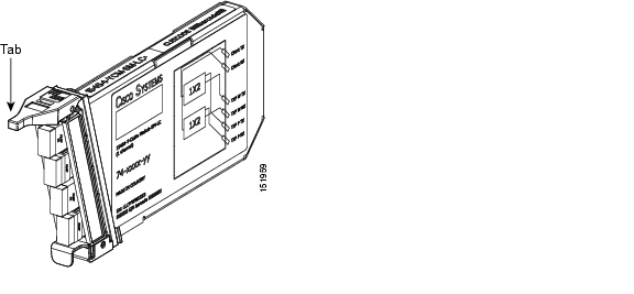
DLP-G33 Install the TCC2 or TCC2P Card
Caution
Note
Step 1
Step 2
Note
Step 3
Note
If you insert a card into a slot provisioned for a different card, all LEDs turn off.
Step 4
a.
•
•
•
•
•
•
•
Note
Note
Note
Note
b.
•
•
•
•
•
•
•
•
Note
Note
Note
Note
Step 5
Step 6
Step 7
Refer to the release-specific software upgrade document to replace the software. To replace the TCC2/TCC2P card, refer to the Cisco ONS 15454 DWDM Troubleshooting Guide.
Step 8
Tip
Note
Note
Step 9
DLP-G34 Install the AIC-I Card
Note
Step 1
Step 2
Step 3
Note
Step 4
•
Note
•
•
Note
Note
Note
Step 5
DLP-G309 Install the MS-ISC-100T Card
Note
Note
Step 1
Step 2
Step 3
Note
Step 4
•
•
•
•
•
Note
Note
Step 5
Step 6
NTP-G145 Connect a Multishelf Node and Subtending Shelves to an MS-ISC-100T Card
Purpose
Use this procedure to connect a multishelf node and subtending shelves to two MS-ISC-100T cards.
Tools/Equipment
5.9 in. (0.15 m) CAT-5 LAN cable (2)
19.69 in. (0.5 m) CAT-5 LAN cable (1)
Cross-over (CAT-5) LAN cables (2 for each subtending shelf)
EAP cables (2)
Prerequisite Procedures
G15 Install the Common Control Cards
Required/As Needed
As needed
Onsite/Remote
Onsite
Security Level
None
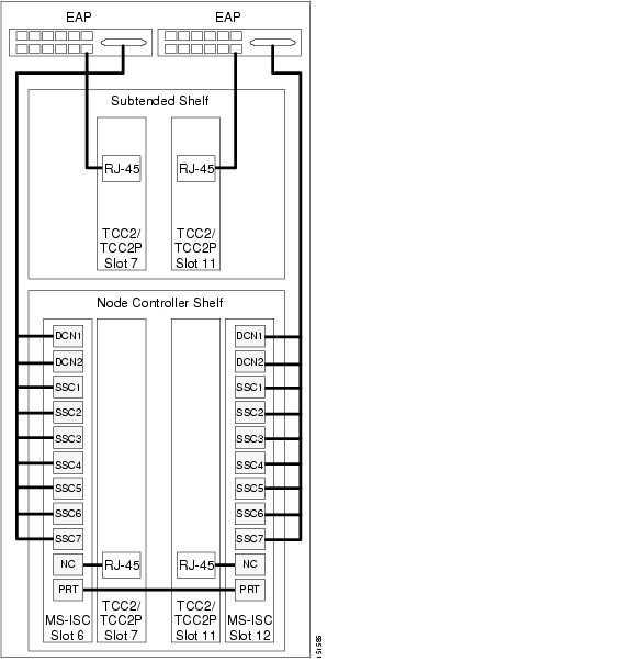
Step 1
a.
b.
c.
d.
e.
Figure 1-32 Connecting the EAP to the Node Controller and Subtending Shelf
Step 2
a.
b.
c.
Stop. You have completed this procedure.
NTP-G158 Connect a Multishelf Node and Subtending Shelves to a Cisco Catalyst 2950
Step 1
Step 2
Step 3
Step 4
a.
b.
c.
NTP-G159 Configure a Cisco Catalyst 2950 for a Multishelf Node
Purpose
This procedure configures in IOS the Cisco Catalyst 2950 for a multishelf node configuration. For more information about the Catalyst 2950, refer to the Catalyst 2950 product documentation.
Tools/Equipment
None
Prerequisite Procedures
G158 Connect a Multishelf Node and Subtending Shelves to a Cisco Catalyst 2950
Required/As Needed
Required
Onsite/Remote
Onsite or remote
Security Level
Superuser
Note
Step 1
Switch(config)#spanning-tree mode rapid-pvstSwitch(config)#no spanning-tree optimize bpdu transmissionSwitch(config)#spanning-tree extend system-idStep 2
(Switch(config)#interface FastEthernet0/1(Switch(config-if)#switchport trunk allowed vlan 1,2(Switch(config-if)#switchport mode trunk(Switch(config-if)#switchport nonegotiateStep 3
(Switch(config)#interface FastEthernet0/port(Switch(config-if)#switchport access vlan 2(Switch(config-if)#switchport mode accessStep 4
(Switch(config)#interface FastEthernet0/9 - 21(Switch(config-if)#shutdownStep 5
(Switch(config)#interface FastEthernet0/22(Switch(config-if)#switchport trunk allowed vlan 1,2(Switch(config-if)#switchport mode trunkStep 6
(Switch(config)#interface FastEthernet0/port(Switch(config-if)#switchport mode accessStep 7
(Switch(config)#interface GigabitEthernet0/1(Switch(config)#no ip address(Switch(config)#ip http server(Switch(config)#interface GigabitEthernet0/2(Switch(config)#no ip address(Switch(config)#ip http server(Switch(config)#interface Vlan1(Switch(config)#no ip address(Switch(config)#no ip route-cache(Switch(config)#ip http serverStep 8
Switch(config)#line con 0Switch(config)#line vty 0 4Switch(config-line)#password yyyyyySwitch(config-line)#loginSwitch(config-line)#line vty 5 15Switch(config-line)#password yyyyyySwitch(config-line)#loginSwitch(config-line)#endStop. You have completed this procedure.
NTP-G16 Perform the Shelf Installation Acceptance Test
Purpose
Use this procedure to perform a shelf installation acceptance test for the ONS 15454 ETSI and ONS 15454 ANSI.
Tools/Equipment
Voltmeter
Oval and/or block ferrites
Prerequisite Procedures
Applicable procedures in "Install the Shelf and Common Control Cards"
Required/As Needed
Required
Onsite/Remote
Onsite
Security Level
None
Step 1
Table 1-12 ONS 15454 ETSI Shelf Installation Task Summary
G10 Attach Wires to Alarm, Timing, LAN, and Craft Pin Connections
G145 Connect a Multishelf Node and Subtending Shelves to an MS-ISC-100T Card or G158 Connect a Multishelf Node and Subtending Shelves to a Cisco Catalyst 2950
G159 Configure a Cisco Catalyst 2950 for a Multishelf Node (if you completed G158 Connect a Multishelf Node and Subtending Shelves to a Cisco Catalyst 2950)
Step 2
Table 1-13 ONS 15454 ANSI Shelf Installation Task Summary
G10 Attach Wires to Alarm, Timing, LAN, and Craft Pin Connections
G11 Install an External Wire-Wrap Panel on the AEP (ANSI Only)
G145 Connect a Multishelf Node and Subtending Shelves to an MS-ISC-100T Card or G158 Connect a Multishelf Node and Subtending Shelves to a Cisco Catalyst 2950
G159 Configure a Cisco Catalyst 2950 for a Multishelf Node (if you completed G158 Connect a Multishelf Node and Subtending Shelves to a Cisco Catalyst 2950)
Step 3
Step 4
Step 5
Stop. You have completed this procedure.
DLP-G35 Inspect the Shelf Installation and Connections
Step 1
Step 2
Step 3
DLP-G36 Measure Voltage
Step 1
a.
b.
Step 2
a.
•
•
•
Step 3
Step 4
![]()
![]()
![]()
![]()
![]()
![]()
![]()
![]()
Posted: Thu Sep 13 00:38:32 PDT 2007
All contents are Copyright © 1992--2007 Cisco Systems, Inc. All rights reserved.
Important Notices and Privacy Statement.