cc/td/doc/product/ong/15400/r70docs
hometocprevnextglossaryfeedbacksearchhelp
PDF

Table Of Contents

Connect the PC and Log into the GUI

Before You Begin

NTP-G17 Set Up Computer for CTC

DLP-G37 Run the CTC Installation Wizard for Windows PCs

DLP-G38 Run the CTC Installation Wizard for Solaris Workstations

DLP-G52 Change the JRE Version

NTP-G18 Set Up CTC Computer for Local Craft Connection to the ONS 15454

DLP-G39 Set Up a Windows PC for Craft Connection to an ONS 15454 on the Same Subnet Using Static IP Addresses

DLP-G40 Set Up a Windows PC for Craft Connection to an ONS 15454 Using Dynamic Host Configuration Protocol

DLP-G41 Set Up a Windows PC for Craft Connection to an ONS 15454 Using Automatic Host Detection

DLP-G42 Set Up a Solaris Workstation for a Craft Connection to an ONS 15454

NTP-G19 Set Up a CTC Computer for a Corporate LAN Connection to the ONS 15454

DLP-G43 Disable or Bypass Proxy Service Using Internet Explorer (Windows)

DLP-G44 Disable or Bypass Proxy Service Using Netscape (Windows) or Mozilla (Solaris)

NTP-G21 Log into the ONS 15454 GUI

DLP-G331 Adjust the Java Virtual Memory Heap Size (Windows)

DLP-G46 Log into CTC

DLP-G47 Install Public-Key Security Certificate

DLP-G48 Create Login Node Groups

DLP-G49 Add a Node to the Current Session or Login Group

DLP-G50 Delete a Node from the Current Session or Login Group

DLP-G51 Delete a Node from a Specific Login Node Group

DLP-G53 Configure the CTC Alerts Dialog Box for Automatic Popup


Connect the PC and Log into the GUI


This chapter explains how to connect Windows PCs and Solaris workstations to the Cisco ONS 15454 and how to log into Cisco Transport Controller (CTC) software, which is the ONS 15454 Operation, Administration, Maintenance and Provisioning (OAM&P) user interface. Procedures for connecting to the ONS 15454 ANSI using TL1 are provided in the Cisco ONS SONET TL1 Command Guide. Procedures for connecting to the ONS 15454 ETSI using TL1 are provided in the Cisco ONS 15454 SDH TL1 Command Guide.


Note Unless otherwise specified, "ONS 15454" refers to both ANSI and ETSI shelf assemblies.


Before You Begin

This section lists the chapter procedures (NTPs). Turn to a procedure for applicable tasks (DLPs).

1. G17 Set Up Computer for CTC—Complete this procedure if your Windows PC or Solaris workstation has never been connected to an ONS 15454.

2. G18 Set Up CTC Computer for Local Craft Connection to the ONS 15454—Complete this procedure to set up your computer for an onsite craft connection to the ONS 15454.

3. G19 Set Up a CTC Computer for a Corporate LAN Connection to the ONS 15454—Complete this procedure to set up your computer to connect to the ONS 15454 using a corporate LAN.

4. G21 Log into the ONS 15454 GUI—Complete this procedure to log into CTC.

NTP-G17 Set Up Computer for CTC

Purpose

This procedure configures your Windows PC or Solaris workstation to run CTC.

Tools/Equipment

Cisco ONS 15454 Release 7.0 software CD

Prerequisite Procedures

Chapter 1, "Install the Shelf and Common Control Cards"

Required/As Needed

Required

Onsite/Remote

Onsite or remote

Security Level

None


Note JRE 1.4.2 or JRE 5.0 is required to log into nodes running Software Release 7.0. (5.0 is the Sun Microsystems version number for JRE 1.5.0.) To log into nodes running Software R4.5 or earlier, you must uninstall JRE 1.4.2 or 5.0 and install JRE 1.3.1. JRE 1.4.2 is provided on the Software R7.0 software CD. Complete the "DLP-G52 Change the JRE Version" task as needed.


Step 1 If your computer does not have an appropriate browser installed, complete the following:

To install Netscape 7.x on a Windows PC, download the browser from the following site: http://channels.netscape.com/ns/browsers/default.jsp

To install Internet Explorer 6.x on a Windows PC, download the browser from the following site: http://www.microsoft.com\

To install Mozilla 1.7 on a Solaris workstation, download the browser from the following site: http://www.mozilla.org/releases/#1.7.12


Note For Windows PCs, only Internet Explorer 6.x and Netscape 7.x are supported. For Solaris workstations, Mozilla 1.7 is the only supported browser.


Step 2 (Windows PC only) Complete the "DLP-G331 Adjust the Java Virtual Memory Heap Size (Windows)" task to increase the size of the JVM heap to improve CTC performance.

Step 3 Complete one of the following:

If your computer is a Windows PC, complete the "DLP-G37 Run the CTC Installation Wizard for Windows PCs" task.

If your computer is a Solaris workstation, complete the "DLP-G38 Run the CTC Installation Wizard for Solaris Workstations" task.

Stop. You have completed this procedure.


DLP-G37 Run the CTC Installation Wizard for Windows PCs

Purpose

This task installs the CTC online user manuals, Acrobat Reader 6.0.1, JRE 1.4.2, and the CTC JAR files on Windows PCs.

Tools/Equipment

Cisco ONS 15454 Release 7.0 software CD

Prerequisite Procedures

None

Required/As Needed

This task is required if you will use a Windows computer to run CTC and if any one of the following is true:

JRE 1.4.2 or JRE 5.0 is not installed.

CTC online user manuals are not installed and are needed.

CTC JAR files are not installed and are needed.

Onsite/Remote

Onsite or remote

Security Level

None


Note If you will log into nodes running CTC software earlier than Release 4.6, uninstall JRE 1.4.2 or 5.0 and reinstall JRE 1.3.1. To run Software R7.0, uninstall JRE 1.3.1 and reinstall JRE 1.4.2 or 5.0. Software R7.0 supports JRE 1.4.2 or JRE 5.0; JRE 1.4.2 is provided on the software CD.


Step 1 Verify that your computer has the following:

Processor—Pentium III, 700 Mhz or faster

RAM—384 MB recommended, 512 MB optimum

Hard drive—20 GB hard drive recommended with at least 50 MB of space available

Operating system—Windows 98 (1st and 2nd editions), Windows NT 4.0 (with Service Pack 6a), Windows 2000 (with Service Pack 3), or Windows XP with Service Pack 1

If your operating system is Windows NT 4.0, verify that Service Pack 6a or later is installed. From the Start menu, choose Programs > Administrative Tools > Windows NT Diagnostics and check the service pack on the Version tab of the Windows NT Diagnostics dialog box. If Service Pack 6a or later is not installed, do not continue. Install Service Pack 6a following the computer upgrade procedures for your site.


Note Processor and RAM requirements are guidelines. CTC performance is faster if your computer has a faster processor and more RAM.


Step 2 Insert the Cisco ONS 15454 Release 7.0 software CD into your computer CD drive. The installation program begins running automatically. If it does not start, navigate to the CD directory and double-click setup.exe.

The Cisco Transport Controller Installation Wizard displays the components that will be installed on your computer:

Java Runtime Environment 1.4.2

Acrobat Reader 6.0.1

Online User Manuals

CTC JAR files


Note JRE 1.4.2 or 5.0 is required to run Release 7.0. Preinstalling the CTC JAR files saves time at initial login. If the JAR files are not installed, they are downloaded from the TCC2/TCC2P card the first time you log in.


Step 3 Click Next.

Step 4 Complete one of the following:

Click Typical to install the Java Runtime Environment, CTC JAR files, online user manuals, and Acrobat Reader. If you already have JRE 1.4.2 or 5.0 installed on your computer, choose Custom.

Click Custom if you want to choose the components that you want to install. By default, Acrobat Reader and the online user manuals are selected.

Step 5 Click Next.

Step 6 Complete the following, as applicable:

If you selected Typical in Step 4, skip this step and continue with Step 7.

If you selected Custom in Step 4, check the CTC component that you want to install and click Next.

If you selected Online User Manuals, continue with Step 7.

If you did not select Online User Manuals, continue with Step 9.

Step 7 The directory where the installation wizard will install the CTC online user manuals appears. The default is C:\Program Files\Cisco\CTC\Documentation.

If you want to change the CTC online user manuals directory, type the new directory path in the Directory Name field, or click Browse to navigate to the directory.

If you do not want to change the directory, continue with Step 8.

Step 8 Click Next.

Step 9 Review the components that will be installed. If you want to change the components, complete one of the following. If not, proceed to Step 10.

If you selected Typical in Step 4, click Back twice to return to the installation setup type page. Choose Custom and repeat Steps 5 through 8.

If you selected Custom in Step 4, click Back once or twice (depending on the components selected) until the component selection page appears. Repeat Steps 5 through 8.

Step 10 Click Next. It might take a few minutes for the JRE installation wizard to appear. If you selected Custom in Step 4 and you don't need to install a JRE, continue with Step 12.

Step 11 To install the JRE, complete the following:

a. In the Java 2 Runtime Environment License Agreement dialog box, view the license agreement and choose one of the following:

I accept the terms of the license agreement—Accepts the license agreement. Continue with Step  b.

I do not accept the terms of the license agreement—Disables the Next button on the Java 2 Runtime Environment License Agreement dialog box. Click Cancel to return to the CTC installation wizard. CTC will not install the JRE. Continue with Step 12.


Note If JRE 1.4.2 is already installed on your computer, the License Agreement dialog box does not appear. You must click Next and then choose Modify to change the JRE installation, or Remove to uninstall the JRE. If you choose Modify and click Next, continue with Step  e. If you choose Remove and click Next, continue with Step  i.


b. Click Next.

c. Choose one of the following:

Click Typical to install all JRE features. If you select Typical, the JRE version installed will automatically become the default JRE version for your browsers.

Click Custom if you want to select the components to install and select the browsers that will use the JRE version.

d. Click Next.

e. If you selected Typical, continue with Step  i. If you selected Custom, click the drop-down list for each program feature that you want to install and choose the desired setting. The program features include:

Java 2 Runtime Environment—(Default) Installs JRE 1.4.2 with support for European languages.

Support for Additional Languages—Adds support for non-European languages.

Additional Font and Media Support—Adds Lucida fonts, Java Sound, and color management capabilities.

The drop-down list options for each program feature include:

This feature will be installed on the local hard drive—Installs the selected feature.

This feature and all subfeatures will be installed on the local hard drive—Installs the selected feature and all subfeatures.

Don't install this feature now—Does not install the feature (not an option for Java 2 Runtime Environment).

To modify the directory where the JRE version is installed, click Change, navigate to the desired directory, and click OK.

f. Click Next.

g. In the Browser Registration dialog box, check the browsers that you want to register with the Java Plug-In. The JRE version will be the default for the selected browsers. It is acceptable to leave both browser check boxes unchecked.


Note Setting the JRE as the default for these browsers might cause problems with these browsers.


h. Click Next.

i. Click Finish.


Note If you are uninstalling the JRE, click Remove.


Step 12 In the Cisco Transport Controller Installation Wizard, click Next. The online user manuals and/or Acrobat Reader are installed.

Step 13 Click Finish.

Step 14 Return to your originating procedure (NTP).


DLP-G38 Run the CTC Installation Wizard for Solaris Workstations

Purpose

This task installs the CTC online user manuals, Acrobat 6.0.1, and JRE 1.4.2 on Solaris workstations, as necessary.

Tools/Equipment

Cisco ONS 15454 Release 7.0 software CD

Prerequisite Procedures

None

Required/As Needed

This task is required if you will use a Solaris workstation to run CTC and any of the following are true:

JRE 1.4.2 or 5.0 is not installed.

CTC online user manuals are not installed and are needed.

Onsite/Remote

Onsite or remote

Security Level

None


Note If you will log into nodes running CTC software earlier than Release 4.6, uninstall JRE 1.4.2 or 5.0 and reinstall JRE 1.3.1. To run Software R7.0, uninstall JRE 1.3.1 and reinstall JRE 1.4.2 or 5.0. Software R7.0 supports JRE 1.4.2 or JRE 5.0; JRE 1.4.2 is provided on the software CD.


Step 1 Verify that your computer has the following:

RAM—384 MB recommended, 512 MB optimum

Hard drive—20 GB hard drive recommended with at least 50 MB of space available

Operating system—Solaris 8 or 9


Note These requirements are guidelines. CTC performance is faster if your computer has a faster processor and more RAM.


Step 2 Change the directory. Type:

cd /cdrom/cdrom0/

Step 3 From the techdoc454 CD directory, type:

./setup.bat

The Cisco Transport Controller Installation Wizard displays the components that will be installed on your computer:

Java Runtime Environment 1.4.2

Acrobat Reader 6.0.1

Online User Manuals

CTC JAR files

Step 4 Click Next.

Step 5 Complete one of the following:

Click Typical to install both the Java Runtime Environment and online user manuals. If you already have JRE 1.4.2 or 5.0 installed on your computer, choose Custom.

Click Custom if you want to install either the JRE or the online user manuals.

Step 6 Click Next.

Step 7 Complete the following, as applicable:

If you selected Typical in Step 5, continue with Step 8.

If you selected Custom in Step 5, check the CTC component that you want to install and click Next.

If you selected Online User Manuals, continue with Step 8.

If you did not select Online User Manuals, continue with Step 10.

Step 8 The directory where the installation wizard will install the CTC online user manuals appears. The default is /usr/doc/ctc.

If you want to change the CTC online user manuals directory, type the new directory path in the Directory Name field, or click Browse to navigate to the directory.

If you do not want to change the CTC online user manuals directory, skip this step.

Step 9 Click Next.

Step 10 Review the components that will be installed.

If you selected Typical in Step 5, click Back twice to return to the installation setup type page. Choose Custom and repeat Steps 6 through 9.

If you selected Custom in Step 5, click Back once or twice (depending on the components selected) until you reach the component selection page and check the desired components. Repeat Steps 7 through  9.

Step 11 Click Next. It might take a few minutes for the JRE installation wizard to appear. If you selected Custom in Step 4 and need to install the JRE, continue with Step 13.

Step 12 To install the JRE, complete the following:

a. In the Java 2 Runtime Environment License Agreement dialog box, view the license agreement and choose one of the following:

I accept the terms of the license agreement—Accepts the license agreement. Continue with Step  b.

I do not accept the terms of the license agreement—Disables the Next button on the Java 2 Runtime Environment License Agreement dialog box. Click Cancel to return to the CTC installation wizard. CTC will not install the JRE. Continue with Step 13.


Note If JRE 1.4.2 is already installed on your computer, the License Agreement dialog box does not appear. You must click Next and then choose Modify to change the JRE installation or Remove to uninstall the JRE. If you choose Modify and click Next, continue with Step  e. If you choose Remove and click Next, continue with Step  i.


b. Click Next.

c. Choose one of the following:

Click Typical to install all JRE features. If you select Typical, the JRE version installed will automatically become the default JRE version for your browsers.

Click Custom if you want to select the components to install and select the browsers that will use the JRE version.

d. Click Next.

e. If you selected Typical, continue with Step  i. If you selected Custom, click the drop-down list for each program feature that you want to install and choose the desired setting. The program features include:

Java 2 Runtime Environment—(Default) Installs JRE 1.4.2 with support for European languages.

Support for Additional Languages—Adds support for non-European languages.

Additional Font and Media Support—Adds Lucida fonts, Java Sound, and color management capabilities.

The drop-down list options for each program feature include:

This feature will be installed on the local hard drive—Installs the selected feature.

This feature and all subfeatures will be installed on the local hard drive—Installs the selected feature and all subfeatures.

Don't install this feature now—Does not install the feature (not an option for Java 2 Runtime Environment).

To modify the directory where the JRE version is installed, click Change, navigate to the desired directory, and click OK.

f. Click Next.

g. In the Browser Registration dialog box, check the browsers that you want to register with the Java Plug-In. The JRE version will be the default for the selected browsers. It is acceptable to leave both browser check boxes unchecked.


Note Setting the JRE version as the default for these browsers might cause problems with these browsers.


h. Click Next.

i. Click Finish.


Note If you are uninstalling the JRE, click Remove.


Step 13 In the Cisco Transport Controller Installation Wizard, click Next. The online user manuals are installed.

Step 14 Click Finish.


Note Be sure to record the names of the directories you choose for JRE and the online user manuals.


Step 15 Return to your originating procedure (NTP).


DLP-G52 Change the JRE Version

Purpose

This task changes the JRE version, which is useful if you would like to upgrade to a later JRE version from an earlier one without using the software or documentation CD. This does not affect the browser default version. After selecting the desired JRE version, you must exit CTC. The next time you log into a node, the new JRE version will be used.

Tools

None

Prerequisite Procedures

G46 Log into CTC

Required/As Needed

As needed

Onsite/Remote

Onsite or remote

Security Level

Provisioning or higher


Step 1 From the Edit menu, choose Preferences.

Step 2 Click the JRE tab. The JRE tab shows the current JRE version and the recommended and supported versions.

Step 3 Click the Browse button and navigate to the JRE directory on your computer.

Step 4 Choose the JRE version.

Step 5 Click Open, then click OK.

Step 6 From the File menu, choose Exit.

Step 7 In the confirmation dialog box, click Yes.

Step 8 Log out of the ONS node.

Step 9 In the web browser that you used to log into the node, click Delete CTC Cache.

Step 10 Click Yes on the confirmation dialog box, then close the browser window.

Step 11 Complete the "DLP-G46 Log into CTC" task.

Step 12 Return to your originating procedure (NTP).


NTP-G18 Set Up CTC Computer for Local Craft Connection to the ONS 15454

Purpose

This procedure explains how to set up a PC running Windows or a Solaris workstation for an onsite local craft connection to the ONS 15454.

Tools/Equipment

Network interface card (NIC), also referred to as an Ethernet card

Straight-through (CAT-5) LAN cable

Prerequisite Procedures

G17 Set Up Computer for CTC

Required/As Needed

As needed

Onsite/Remote

Onsite or remote

Security Level

None


Step 1 Complete one of the CTC computer setup tasks shown in Table 2-1 based on your CTC connection environment. For initial setup, use Option 1 or 3 if you are setting up a Windows PC. Use Option 4 if you are setting up a Solaris workstation.

Table 2-1 CTC Computer Setup for Local Craft Connections to the ONS 15454 

Option
CTC Connection Environment
CTC Computer Setup Task 

1

You are connecting from a Windows PC.

You will connect to one ONS 15454.

You need to access non-ONS 15454 applications such as ping and tracert (trace route).

G39 Set Up a Windows PC for Craft Connection to an ONS 15454 on the Same Subnet Using Static IP Addresses

2

You are connecting from a Windows PC.

Your network uses Dynamic Host Configuration Protocol (DHCP) for assignment of host IP addresses.

The CTC computer is provisioned for DHCP.

The ONS 15454 has DHCP forwarding enabled.

The ONS 15454 is connected to a DHCP server.

Note The ONS 15454 does not provide IP addresses. If DHCP is enabled, it passes DCHP requests to an external DHCP server.

G40 Set Up a Windows PC for Craft Connection to an ONS 15454 Using Dynamic Host Configuration Protocol

Note Do not use this task for initial node turn-up. Use the task only if DHCP forwarding is enabled on the ONS 15454. By default, DHCP is not enabled. To enable it, see the "NTP-G26 Set Up CTC Network Access" procedure on page 3-13.

3

You are connecting from a Windows PC.

You will connect to ONS 15454s at different locations and times and do not wish to reconfigure your PC's IP settings each time.

You will not access or use non-ONS 15454 applications such as ping and tracert (trace route).

If you are using an ANSI shelf, you will connect to the TCC2/TCC2P Ethernet port or backplane LAN pins either directly or through a hub.

If you are using an ETSI shelf, you will connect to the ONS 15454 Ethernet port or the RJ-45 jack on the MIC-C/T/P FMEC either directly or through a hub.

If you are using an ANSI or ETSI multishelf node, you will connect to the patch panel DCN port or the Catalyst 2950 using a straight-through (CAT 5) LAN cable.

G41 Set Up a Windows PC for Craft Connection to an ONS 15454 Using Automatic Host Detection

4

You are connecting from a Solaris workstation.

You will connect to one ONS 15454.

You need to access non-ONS 15454 applications such as ping and tracert (trace route).

G42 Set Up a Solaris Workstation for a Craft Connection to an ONS 15454


Step 2 Connect a straight-through CAT-5 LAN cable from the Windows PC or Solaris workstation NIC to one of the following:

The RJ-45 (LAN) port on the active or standby TCC2/TCC2P card. Use this method for the initial shelf turn-up.

The RJ-45 (LAN) port on a hub or switch to which the ONS 15454 is physically connected

For multishelf mode, the DCN RJ-45 (LAN) port on the Ethernet Adapter Panel (EAP) or Port 23 or 24 of the Catalyst 2950


Note For instructions on crimping your own straight-through (CAT-5) LAN cables, refer to the Cisco ONS 15454 DWDM Troubleshooting Guide.


Step 3 After setting up your CTC computer, continue with the "G21 Log into the ONS 15454 GUI" procedure as needed.

Stop. You have completed this procedure.


DLP-G39 Set Up a Windows PC for Craft Connection to an ONS 15454 on the Same Subnet Using Static IP Addresses

Purpose

This task sets up your computer for a local craft connection to the ONS 15454 when:

You will connect to one ONS 15454; if you will connect to multiple ONS 15454s, you might need to reconfigure your computer's IP settings each time you connect to an ONS 15454.

You need to use non-ONS 15454 applications such as ping and tracert (trace route).

Tools/Equipment

None

Prerequisite Procedures

G17 Set Up Computer for CTC

Required/As Needed

As needed

Onsite/Remote

Onsite

Security Level

None


Step 1 Verify the operating system that is installed on your computer:

a. From the Windows Start menu, choose Settings > Control Panel.

b. In the Control Panel window, double-click the System icon.

c. On the General tab of the System Settings window, verify that the Windows operating system is one of the following: Windows 98, Windows NT 4.0, Windows 2000, or Windows XP.

Step 2 According to the Windows operating system installed on your computer, perform one of the following steps:

For Windows 98, complete Step 3.

For Windows NT 4.0, complete Step 4.

For Windows 2000, complete Step 5.

For Windows XP, complete Step 6.

Step 3 If you have Windows 98 installed on your PC, complete the following steps to change its TCP/IP configuration:

a. From the Windows Start menu, choose Settings > Control Panel.

b. In the Control Panel dialog box, click the Network icon.

c. In the Network dialog box, choose TCP/IP for your NIC card, then click Properties.

d. In the TCP/IP Properties dialog box, click the DNS Configuration tab and choose Disable DNS.

e. Click the WINS Configuration tab and choose Disable WINS Resolution.

f. Click the IP Address tab.

g. In the IP Address window, click Specify an IP address.

h. In the IP Address field, enter an IP address that is identical to the ONS 15454 IP address except for the last octet. The last octet must be 1 or 3 through 254. This IP address appears on the LCD unless its display is suppressed during node provisioning.

i. In the Subnet Mask field, type the same subnet mask as the ONS 15454. The default is 255.255.255.0 (24 bit).

j. Click OK.

k. In the TCP/IP dialog box, click the Gateway tab.

l. In the New Gateway field, type the ONS 15454 IP address. Click Add.

m. Verify that the IP address appears in the Installed Gateways field, then click OK.

n. When the prompt to restart your PC appears, click Yes.

o. Proceed to Step 7.

Step 4 If you have Windows NT 4.0 installed on your PC, complete the following steps to change its TCP/IP configuration:

a. From the Windows Start menu, choose Settings > Control Panel.

b. In the Control Panel dialog box, click the Network icon.

c. In the Network dialog box, click the Protocols tab, choose TCP/IP Protocol, then click Properties.

d. Click the IP Address tab.

e. In the IP Address window, click Specify an IP address.

f. In the IP Address field, enter an IP address that is identical to the ONS 15454 IP address shown on the ONS 15454 LCD except for the last octet. The last octet must be 1 or 3 through 254.

g. In the Subnet Mask field, type 255.255.255.0.

h. Click Advanced.

i. In the Gateways List, click Add. The TCP/IP Gateway Address dialog box appears.

j. Type the ONS 15454 IP address in the Gateway Address field.

k. Click Add.

l. Click OK.

m. Click Apply.

n. In some cases, Windows NT 4.0 prompts you to reboot your PC. If you receive this prompt, click Yes.

o. Proceed to Step 7.

Step 5 If you have Windows 2000 installed on your PC, complete the following steps to change its TCP/IP configuration:

a. From the Windows Start menu, choose Settings > Network and Dial-up Connections > Local Area Connection.

b. In the Local Area Connection Status dialog box, choose the local area connection connected to the PC port connected to the ONS 15454.

c. Click Properties.

d. On the General tab, choose Internet Protocol (TCP/IP), then click Properties.

e. Click Use the following IP address.

f. In the IP Address field, enter an IP address that is identical to the ONS 15454 IP address shown on the ONS 15454 LCD except for the last octet. The last octet must be 1 or 3 through 254.

g. In the Subnet Mask field, type 255.255.255.0.

h. In the Default Gateway field, type the ONS 15454 IP address.

i. Click OK.

j. In the Local Area Connection Properties dialog box, click OK.

k. In the Local Area Connection Status dialog box, click Close.

l. Proceed to Step 7.

Step 6 If you have Windows XP installed on your PC, complete the following steps to change its TCP/IP configuration:

a. From the Windows Start menu, choose Control Panel > Network Connections.


Note If the Network Connections menu is not available, right-click the Windows screen and choose Properties from the popup menu. Click the Appearance tab, then under Scheme, choose Classic View.


b. From the Network Connections dialog box, click the Local Area Connection icon.

c. On the General tab of the Local Area Connection Properties dialog box, choose Internet Protocol (TCP/IP), then click Properties.

d. In the IP Address field, enter an IP address that is identical to the ONS 15454 IP address shown on the ONS 15454 LCD except for the last octet. The last octet must be 1 or 3 through 254.

e. In the Subnet Mask field, type 255.255.255.0.

f. In the Default Gateway field, type the ONS 15454 IP address.

g. Click OK.

h. In the Local Area Connection Properties dialog box, click OK.

i. In the Local Area Connection Status dialog box, click Close.

Step 7 Return to your originating procedure (NTP).


DLP-G40 Set Up a Windows PC for Craft Connection to an ONS 15454 Using Dynamic Host Configuration Protocol

Purpose

This task sets up your computer for craft connection to the ONS 15454 using DHCP.

Tools/Equipment

None

Prerequisite Procedures

G17 Set Up Computer for CTC

NTP-G26 Set Up CTC Network Access, page 3-13

Required/As Needed

As needed

Onsite/Remote

Onsite

Security Level

None


Note Do not use this task for initial node turn-up. Use the task only if DHCP forwarding is enabled on the ONS 15454. By default, DHCP is not enabled. To enable it, see the "NTP-G26 Set Up CTC Network Access" procedure on page 3-13.


Note The ONS 15454 does not provide the IP addresses. If DHCP forwarding is enabled, it passes DCHP requests to an external DHCP server.


Step 1 Verify the operating system that is installed on your computer:

a. From the Windows Start menu, choose Settings > Control Panel.

b. In the Control Panel window, double-click the System icon.

c. On the General tab of the System Settings window, verify that the Windows operating system is one of the following: Windows 98, Windows NT 4.0, Windows 2000, or Windows XP.

Step 2 According to the Windows operating system installed on your computer, perform one of the following steps:

For Windows 98, complete Step 3.

For Windows NT 4.0, complete Step 4.

For Windows 2000, complete Step 5.

For Windows XP, complete Step 6.

Step 3 If you have Windows 98 installed on your PC, complete the following steps to change its TCP/IP configuration:

a. From the Windows Start menu, choose Settings > Control Panel.

b. In the Control Panel dialog box, click the Network icon.

c. In the Network dialog box, select TCP/IP for your NIC, then click Properties.

d. In the TCP/IP Properties dialog box, click the DNS Configuration tab and choose Disable DNS.

e. Click the WINS Configuration tab and choose Disable WINS Resolution.

f. Click the IP Address tab.

g. In the IP Address window, click Obtain an IP address automatically.

h. Click OK.

i. When the prompt to restart your PC appears, click Yes.

j. Proceed to Step 7.

Step 4 If you have Windows NT 4.0 installed on your PC, complete the following steps to change its TCP/IP configuration:

a. From the Windows Start menu, choose Settings > Control Panel.

b. In the Control Panel dialog box, click the Network icon.

c. In the Network dialog box, click the Protocols tab, choose TCP/IP Protocol, then click Properties.

d. Click the IP Address tab.

e. In the IP Address window, click Obtain an IP address from a DHCP server.

f. Click OK.

g. Click Apply.

h. If Windows prompts you to restart your PC, click Yes.

i. Proceed to Step 7.

Step 5 If you have Windows 2000 installed on your PC, complete the following steps to change its TCP/IP configuration:

a. From the Windows Start menu, choose Settings > Network and Dial-up Connections > Local Area Connection.

b. In the Local Area Connection Status dialog box, choose the local area connection connected to the PC port connected to the ONS 15454.

c. In the Local Area Connection Status dialog box, click Properties.

d. On the General tab, choose Internet Protocol (TCP/IP), then click Properties.

e. Click Obtain an IP address automatically.

f. Click OK.

g. In the Local Area Connection Properties dialog box, click OK.

h. In the Local Area Connection Status dialog box, click Close.

i. Proceed to Step 7.

Step 6 If you have Windows XP installed on your PC, complete the following steps to change its TCP/IP configuration:

a. From the Windows Start menu, choose Control Panel > Network Connections.


Note If the Network Connections menu is not available, right-click the Windows screen and choose Properties from the popup menu. Click the Appearance tab, then under Scheme, choose Classic View.


b. From the Network Connections dialog box, click the Local Area Connection icon.

c. On the General tab of the Local Area Connection Properties dialog box, click Properties.

d. On the General tab, choose Internet Protocol (TCP/IP), then click Properties.

e. Click Obtain an IP address automatically.

f. Click OK.

g. In the Local Area Connection Properties dialog box, click OK.

h. In the Local Area Connection Status dialog box, click Close.

Step 7 Return to your originating procedure (NTP).


DLP-G41 Set Up a Windows PC for Craft Connection to an ONS 15454 Using Automatic Host Detection

Purpose

This task sets up your computer for local craft connection to the ONS 15454 when:

You are using an ANSI shelf, you will connect to the ONS 15454 Ethernet port or backplane LAN pins either directly or through a hub.

You are using an ETSI shelf, you will connect to the ONS 15454 Ethernet port or the RJ-45 jack on the MIC-C/T/P FMEC either directly or through a hub.

You will connect to multiple ONS 15454s and do not want to reconfigure your IP address each time.

You do not need to access non-ONS 15454 applications such as ping and tracert (trace route).

Tools/Equipment

None

Prerequisite Procedures

G17 Set Up Computer for CTC

Required/As Needed

As needed

Onsite/Remote

Onsite

Security Level

None


Step 1 Verify the operating system that is installed on your computer:

a. From the Windows Start menu, choose Settings > Control Panel or, for Windows XP, Control Panel > System.

b. In the Control Panel window, double-click the System icon.

c. On the General tab of the System Settings window, verify that the Windows operating system is one of the following: Windows 98, Windows NT 4.0, Windows 2000, or Windows XP.

Step 2 According to the Windows operating system installed on your computer, perform one of the following steps:

For Windows 98, complete Step 3.

For Windows NT 4.0, complete Step 4.

For Windows 2000, complete Step 5.

For Windows XP, complete Step 6.

Step 3 If you have Windows 98 installed on your PC, complete the following steps to change its TCP/IP configuration:

a. From the Windows Start menu, choose Settings > Control Panel.

b. In the Control Panel dialog box, click the Network icon.

c. In the Network dialog box, select TCP/IP for your NIC, then click Properties.

d. In the TCP/IP Properties dialog box, click the DNS Configuration tab and choose Disable DNS.

e. Click the WINS Configuration tab and choose Disable WINS Resolution.

f. Click the IP Address tab.

g. In the IP Address window, click Specify an IP address.

h. In the IP Address field, enter any legitimate IP address other than the node IP address as indicated on the LCD of the ONS 15454. The default IP address is 192.1.0.2.


Note You can suppress the LCD IP address display using CTC. For more information, see the "DLP-G162 Change IP Settings" task on page 10-19.


i. In the Subnet Mask field, type the same subnet mask as the ONS 15454. The default is 255.255.255.0 (24 bit).

j. Click OK.

k. In the TCP/IP dialog box, click the Gateway tab.

l. In the New Gateway field, type the address entered in Step h. Click Add.

m. Verify that the IP address appears in the Installed Gateways field, then click OK.

n. When the prompt to restart your PC appears, click Yes.

o. Proceed to Step 7.

Step 4 If you have Windows NT 4.0 installed on your PC, complete the following steps to change its TCP/IP configuration:

a. From the Windows Start menu, choose Settings > Control Panel.

b. In the Control Panel dialog box, click the Network icon.

c. In the Network dialog box, click the Protocols tab, choose TCP/IP Protocol, then click Properties.

d. Click the IP Address tab.

e. In the IP Address window, click Specify an IP address.

f. In the IP Address field, enter any legitimate IP address other than the node IP address as indicated on the LCD of the ONS 15454. The default IP address is 192.1.0.2.


Note You can suppress the LCD IP address display using CTC. For more information, see the "DLP-G162 Change IP Settings" task on page 10-19.


g. In the Subnet Mask field, type the same subnet mask as the ONS 15454. The default is 255.255.255.0 (24 bit).

h. Click Advanced.

i. In the Gateways List, click Add. The TCP/IP Gateway Address dialog box appears.

j. Type the IP address entered in Step  f in the Gateway Address field.

k. Click Add.

l. Click OK.

m. Click Apply.

n. Reboot your PC.

o. Proceed to Step 7.

Step 5 If you have Windows 2000 installed on your PC, complete the following steps to change its TCP/IP configuration:

a. From the Windows Start menu, choose Settings > Network and Dial-up Connections > Local Area Connection.

b. In the Local Area Connection Status dialog box, click Properties.

c. On the General tab, choose Internet Protocol (TCP/IP), then click Properties.

d. Click Use the following IP address.

e. In the IP Address field, enter any legitimate IP address other than the node IP address as indicated on the LCD of the ONS 15454. The default IP address is 192.1.0.2.


Note You can suppress the LCD IP address display using CTC. For more information, see the "DLP-G162 Change IP Settings" task on page 10-19.


f. In the Subnet Mask field, type the same subnet mask as the ONS 15454. The default is 255.255.255.0 (24 bit).

g. Type the IP address entered in Step  e in the Gateway Address field.

h. Click OK.

i. In the Local Area Connection Properties dialog box, click OK.

j. In the Local Area Connection Status dialog box, click Close.

k. Proceed to Step 7.

Step 6 If you have Windows XP installed on your PC, complete the following steps to change its TCP/IP configuration:

a. From the Windows Start menu, choose Control Panel > Network Connections.


Note If the Network Connections menu is not available, click Switch to Classic View.


b. From the Network Connections dialog box, right-click the Local Area Connection icon and select Properties.

c. Scroll to the bottom of the Local Area Connection Properties dialog box. Click Internet Protocol (TCP/IP) to select it, then click Properties.

d. In the IP Address field, enter any legitimate IP address other than the node IP address as indicated on the LCD of the ONS 15454. The default IP address is 192.1.0.2.

e. Select the Use the Following IP Address: radio button.


Note You can suppress the LCD IP address display using CTC. For more information, see the "DLP-G162 Change IP Settings" task on page 10-19.


f. In the Subnet Mask field, type the same subnet mask as the ONS 15454. The default is 255.255.255.0 (24 bit).

g. Type the IP address entered in Step  d in the Gateway Address field.

h. Click OK.

i. In the Local Area Connection Properties dialog box, click Close.

Step 7 Return to your originating procedure (NTP).


DLP-G42 Set Up a Solaris Workstation for a Craft Connection to an ONS 15454

Purpose

This task sets up a Solaris workstation for a craft connection to the ONS 15454.

Tools/Equipment

None

Prerequisite Procedures

G17 Set Up Computer for CTC

Required/As Needed

As needed

Onsite/Remote

Onsite

Security Level

None


Step 1 Log into the workstation as the root user.

Step 2 Check to see if the interface is plumbed by typing:

# ifconfig device

For example:

# ifconfig hme1

If the interface is plumbed, a message similar to the following appears:

hme1:flags=1000842<BROADCAST,RUNNING,MULTICAST,IPv4>mtu 1500 index 2 inet 0.0.0.0 netmask 0

If a message similar to this one appears, go to Step 4.

If the interface is not plumbed, a message similar to the following appears:

ifconfig: status: SIOCGLIFFLAGS: hme1: no such interface.

If a message similar to this one appears, go to Step 3.

Step 3 Plumb the interface by typing:

# ifconfig device plumb

For example:

# ifconfig hme1 plumb

Step 4 Configure the IP address on the interface by typing:

# ifconfig interface ip-address netmask netmask up

For example:

# ifconfig hme0 192.1.0.3 netmask 255.255.255.0 up


Note Enter an IP address that is identical to the ONS 15454 IP address except for the last octet. The last octet must be 1 or 3 through 254.


Step 5 In the Subnet Mask field, type 255.255.255.0. Skip this step if you checked Craft Access Only on the Provisioning > Network > General > Gateway Settings tab.

Step 6 Test the connection:

a. Start Mozilla.

b. Enter the ONS 15454 IP address in the web address (URL) field. If the connection is established, a Java Console window, CTC caching messages, and the Cisco Transport Controller Login dialog box appear. If this occurs, go to Step 2 of the "DLP-G46 Log into CTC" task to complete the login. If the Login dialog box does not appear, complete Steps c and d.

c. At the prompt, type:

ping ONS-15454-IP-address

For example, to connect to an ONS 15454 with a default IP address of 192.1.0.2, type:

ping 192.1.0.2

If your workstation is connected to the ONS 15454, the following message appears:

IP-address is alive


Note Skip this step if you checked the Craft Access Only check box on the Provisioning > Network > General > Gateway Settings tab.


d. If CTC is not responding, a "no answer from x.x.x.x" message appears. Verify the IP and subnet mask information. Check that the cables connecting the workstation to the ONS 15454 are securely attached. Check the link status by typing:

# ndd -set /dev/device instance 0

# ndd -get /dev/device link_status

For example:

# ndd -set /dev/hme instance 0

# ndd -get /dev/hme link_status

A result of "1" means the link is up. A result of "0" means the link is down.


Note Check the man page for ndd. For example, type: # man ndd.


Step 7 Return to your originating procedure (NTP).


NTP-G19 Set Up a CTC Computer for a Corporate LAN Connection to the ONS 15454

Purpose

This procedure sets up your computer to access the ONS 15454 through a corporate LAN.

Tools/Equipment

NIC, also referred to as an Ethernet card

Straight-through (CAT-5) LAN cable

Prerequisite Procedures

G17 Set Up Computer for CTC

The ONS 15454 must be provisioned for LAN connectivity, including IP address, subnet mask, default gateway.

The ONS 15454 must be physically connected to the corporate LAN.

Required/As Needed

As needed

Onsite/Remote

Onsite or remote

Security Level

None


Step 1 If your computer is already connected to the corporate LAN, go to Step 3. If you changed your computer's network settings for craft access to the ONS 15454, change the settings back to the corporate LAN access settings. This generally means:

Set the IP Address on the TCP/IP dialog box back to Obtain an IP address automatically (Windows 2000 and XP) or Obtain an IP address from a DHCP server (Windows NT 4.0).

If your LAN requires that Domain Name System (DNS) or Windows Internet Naming Service (WINS) be enabled, change the setting on the DNS Configuration or WINS Configuration tab of the TCP/IP dialog box.

Step 2 Complete one of the following:

For a single-shelf node, connect a straight-through (CAT-5) LAN cable from the PC or Solaris workstation NIC card to a corporate LAN port.

For a multishelf node, connect a straight-through (CAT-5) LAN cable from the PC or Solaris workstation to the DCN RJ-45 (LAN) port on the EAP or to Port 23 or 24 of the Catalyst 2950.

Step 3 If your computer is connected to a proxy server, disable proxy service or add the ONS 15454 nodes as exceptions. To disable or bypass proxy service, complete one of the following tasks, depending on the web browser that you use:

G43 Disable or Bypass Proxy Service Using Internet Explorer (Windows)

G44 Disable or Bypass Proxy Service Using Netscape (Windows) or Mozilla (Solaris)

Step 4 Continue with the "G21 Log into the ONS 15454 GUI" procedure.

Stop. You have completed this procedure.


DLP-G43 Disable or Bypass Proxy Service Using Internet Explorer (Windows)

Purpose

This task disables or bypasses proxy service for PCs running Internet Explorer.

Tools/Equipment

None

Prerequisite Procedures

G17 Set Up Computer for CTC

Required/As Needed

Required if your computer is connected to a network computer proxy server and your browser is Internet Explorer.

Onsite/Remote

Onsite or remote

Security Level

None


Step 1 From the Start menu, select Settings > Control Panel.


Note If your computer is running Windows XP, you can select Control Panel directly from the Start menu. Make sure that you are in Classic View before continuing with this procedure. To switch to Classic View, right-click the Windows screen and choose Properties from the popup menu. Click the Appearance tab, then under Scheme, choose Classic View.


Step 2 In the Control Panel window, choose Internet Options.

Step 3 In the Internet Properties dialog box, click Connections > LAN Settings.

Step 4 In the LAN Settings dialog box, complete one of the following tasks:

Uncheck Use a proxy server to disable the service.

To bypass the service, leave Use a proxy server selected and click Advanced. In the Proxy Setting dialog box under Exceptions, enter the IP addresses of ONS 15454 nodes that you will access. Separate each address with a semicolon. You can insert an asterisk (*) for the host number to include all the ONS 15454s on your network. Click OK to close each open dialog box.

Step 5 Return to your originating procedure (NTP).


DLP-G44 Disable or Bypass Proxy Service Using Netscape (Windows) or Mozilla (Solaris)

Purpose

This task disables or bypasses proxy service for Windows PCs running Netscape or Solaris workstations running Mozilla.

Tools/Equipment

None

Prerequisite Procedures

G17 Set Up Computer for CTC

Required/As Needed

Required if your computer is connected to a network computer proxy server and your browser is Netscape or Mozilla.

Onsite/Remote

Onsite or remote

Security Level

None


Step 1 Open Netscape (Windows) or Mozilla (Solaris).

Step 2 From the Edit menu, choose Preferences.

Step 3 In the Preferences dialog box under Category, choose Advanced > Proxies.

Step 4 On the right side of the Preferences dialog box under Proxies, perform one of the following options:

Click the Direct connection to the Internet option to disable the proxy server.

Click the Manual proxy configuration option to add exceptions to the proxy server. Under Manual Proxy Configuration in the No Proxy For field, enter the IP addresses of the ONS 15454 nodes that you will access. Separate each address with a comma. Click OK to close each open dialog box.

Step 5 Return to your originating procedure (NTP).


NTP-G21 Log into the ONS 15454 GUI

Purpose

This procedure logs into CTC, the graphical user interface (GUI) software used to manage the ONS 15454. This procedure includes optional node login tasks.

Tools/Equipment

None

Prerequisite Procedures

G17 Set Up Computer for CTC

One of the following procedures:

G18 Set Up CTC Computer for Local Craft Connection to the ONS 15454

G19 Set Up a CTC Computer for a Corporate LAN Connection to the ONS 15454

Required/As Needed

Required

Onsite/Remote

Onsite or remote

Security Level

Retrieve or higher


Step 1 Complete the "DLP-G46 Log into CTC" task.


Note For information about navigating in CTC, see "CTC Information and Shortcuts."


During network topology discovery, CTC polls each node in the network to determine which one contains the most recent version of the CTC software. If CTC discovers a node in the network that has a more recent version of the CTC software than the version you are currently running, CTC generates a message stating that a later version of the CTC has been found in the network. If you have network discovery disabled, CTC will not seek more recent versions of the software. Unreachable nodes are not included in the upgrade discovery.


Note Upgrading the CTC software will overwrite your existing software. You must restart CTC after the upgrade is complete.


Step 2 As needed, complete the "DLP-G48 Create Login Node Groups" task. Login node groups allow you to view and manage nodes that have an IP connection but no data communications channel (DCC) connection to the login node.

Step 3 As needed, complete the "DLP-G49 Add a Node to the Current Session or Login Group" task.

Step 4 As needed, complete the "DLP-G50 Delete a Node from the Current Session or Login Group" task.

Step 5 As needed, complete the "DLP-G331 Adjust the Java Virtual Memory Heap Size (Windows)" task.

Step 6 As needed, complete the "DLP-G51 Delete a Node from a Specific Login Node Group" task.

Step 7 As needed, complete the "DLP-G53 Configure the CTC Alerts Dialog Box for Automatic Popup" task.

Stop. You have completed this procedure.


DLP-G331 Adjust the Java Virtual Memory Heap Size (Windows)

Purpose

This task allows you to adjust the Java Virtual Memory (JVM) heap size of a Windows PC from the default 256 MB to the maximum of 512 MB in order to improve CTC performance.

Tools/Equipment

None

Prerequisite procedures

None

Required/As needed

As needed

Onsite/Remote

Onsite or remote

Security Level

Provisioning or higher


Note The task adjusts the physical memory allocation in the computer RAM so that more space is allocated for CTC. However, less physical memory will be available for other computer processes and programs. If you notice performance degradation of non-CTC programs after completing this task, reduce the JVM allotted to CTC. You may need to repeat the task a few times to find the right balance between JVM allotted to CTC and to other programs on your computer.


Step 1 From the Windows PC, click Start > Settings > Control Panel. > System, or Start > Control Panel > System (Windows XP). The Windows Control Panel appears. The System Properties dialog box appears.

Step 2 Click the Advanced tab.

Step 3 Click Environmental Variables. The Environmental Variables dialog box appears.

Step 4 In the User Variables area, check to see whether a CTC_HEAP variable was created. If yes, complete the following steps. If not, continue with Step 5.

a. Check the CTC_HEAP value. If it is 512, continue with Step 12. If not, continue with Step b.

b. Click the CTC_HEAP variable and click Edit.

c. In the Edit User Variable dialog box, enter the new JVM heap size. This can be any number between 256 and 512 MB.

d. Click OK, then continue with Step 9.

Step 5 click New. The New User Variable dialog box appears.

Step 6 Type "CTC_HEAP" in the Variable Name field.

Step 7 Type "512" in the Variable Value field.

Step 8 Click OK to close the New User Variable dialog box.

Step 9 Click OK to close the Environmental Variables dialog box.

Step 10 Click OK to close the System Properties dialog box.

Step 11 Reboot your PC.

Step 12 Return to your originating procedure (NTP).


DLP-G46 Log into CTC

Purpose

This task logs into the graphical user interface (GUI) of CTC.

Tools/Equipment

None

Prerequisite Procedures

G17 Set Up Computer for CTC

One of the following procedures:

G18 Set Up CTC Computer for Local Craft Connection to the ONS 15454

G19 Set Up a CTC Computer for a Corporate LAN Connection to the ONS 15454

Required/As Needed

Required

Onsite/Remote

Onsite or remote

Security Level

Retrieve or higher


Note For information about CTC views and navigation, see "CTC Information and Shortcuts."


Step 1 From the computer connected to the ONS 15454, start Netscape (Windows PC), Internet Explorer (Windows PC) or Mozilla (Solaris workstation):

If you are using a Windows PC, launch Netscape or Internet Explorer from the Windows Start menu or a shortcut icon.

If you are using a Solaris workstation, navigate to the directory where Mozilla was installed, then type:

# mozilla -install

Step 2 In the Netscape, Internet Explorer, or Mozilla web address (URL) field, enter the ONS 15454 IP address. For initial setup, this is the default IP address, 192.1.0.2.


Note The IP address appears on the LCD. You can suppress the LCD IP address display using CTC after you log in. For more information, see the "DLP-G162 Change IP Settings" task on page 10-19.


Step 3 Press Enter. The browser displays a window with a Delete CTC Cache field and information about the Cisco Transport Controller Java and System environments.


Note The Delete CTC Cache field deletes the CTC JAR (Java Archive) files that are downloaded to your computer when you log into an ONS 15454. You perform this action if connectivity problems occur or you want to delete older CTC JAR file versions from your computer. For more information, refer to the "General Troubleshooting" chapter in the Cisco ONS 15454 DWDM Troubleshooting Guide and the "CTC Operations" chapter in the Cisco ONS 15454 DWDM Reference Manual.


Note If you are logging into ONS 15454 nodes in an operation network that are running different releases of CTC software, log into the node running the most recent release. If you log into a node running an older release, you will receive an INCOMPATIBLE-SW alarm for each node in the network running a new release, and CTC will not be able to manage these nodes. To check the software version of a node, select About CTC from the CTC Help menu. This will display the ONS 15454 software version for each node visible on the network view. If the node is not visible, the software version can be read from the LCD display. To resolve an alarm, refer to the Cisco ONS 15454 DWDM Troubleshooting Guide.


Step 4 If a Java Plug-in Security Warning dialog box appears, complete the "DLP-G47 Install Public-Key Security Certificate" task to install the public-key security certificate required by Software Release 4.1 and later.

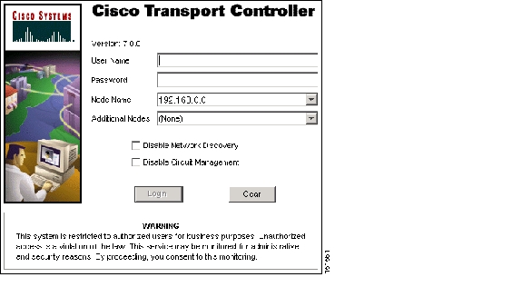
After you complete the security certificate dialog box (or if the certificate is already installed), a Java Console window displays the CTC file download status. The web browser displays information about your Java and system environments. If this is the first login, CTC caching messages appear while CTC files are downloaded to your computer. The first time you connect to an ONS 15454, this process can take several minutes. After the download, the CTC Login dialog box appears. ( Figure 2-1).

Figure 2-1 Logging into CTC


Note When the CTC Login dialog box appears, it might be minimized.


Step 5 In the Login dialog box, type a user name and password (both are case sensitive). For initial setup, type the user name CISCO15 and the password otbu+1.


Note The CISCO15 user is provided with every ONS 15454. CISCO15 has Superuser privileges, so you can create other users. You must create another Superuser before you can delete the CISCO15 user. CISCO15 is delivered with the otbu+1 password. To change the password for CISCO15, complete the "DLP-G191 Change User Password and Security Level on a Single Node" task on page 10-54 after you log in.


Step 6 Each time you log into an ONS 15454, you can make selections about the following login options:

Node Name—Displays the IP address entered in the web browser and a drop-down list of previously entered ONS 15454 IP addresses. You can select any ONS 15454 on the list for the login, or you can enter the IP address (or node name) of any new node where you want to log in.

Additional Nodes—Displays a list of current login node groups. To create a login node group or add additional groups, see the "DLP-G48 Create Login Node Groups" task.

Disable Network Discovery—Check this box to view only the ONS 15454 (and additional nodes within the login node group, if any) entered in the Node Name field. Nodes linked to this node through DCCs are not discovered and will not appear in CTC network view. Using this option can decrease the CTC startup time in networks with many DCC-connected nodes, and can reduce memory consumption.

Disable Circuit Management—Check this box to disable discovery of existing circuits. Using this option can decrease the CTC initialization time in networks with many existing circuits and reduce memory consumption. After you are logged in, you can enable circuit discovery at any time by choosing the Enable Circuit Discovery button on the Circuits tab.

Step 7 If you keep Disable Network Discovery unchecked, CTC attempts to upgrade the CTC software by downloading more recent versions of the JAR files it finds during the network discovery. Click Yes to allow CTC to download the newer JAR files, or No to prevent CTC from downloading the JAR files.


Note Upgrading the CTC software will overwrite your existing software. You must restart CTC after the upgrade is complete.


Step 8 Click Login.

If the login is successful, the CTC node view window (in single-shelf mode) or multishelf view window (in multishelf mode) appears. From here, you can navigate to other CTC views to provision and manage the ONS 15454. If you need to turn up the shelf for the first time, see Chapter 3, "Turn Up a Node." If login problems occur, refer to the Cisco ONS 15454 DWDM Troubleshooting Guide.

Step 9 Return to your originating procedure (NTP).


DLP-G47 Install Public-Key Security Certificate

Purpose

This task installs the ITU Recommendation X.509 public-key security certificate. The public-key certificate is required to run Software Release 4.1 or later.

Tools/Equipment

None

Prerequisite Procedures

This task is performed during the "DLP-G46 Log into CTC" task. You cannot perform it outside of this task.

Required/As Needed

Required

Onsite/Remote

Onsite or remote

Security Level

Provisioning or higher


Step 1 If the Java Plug-in Security Warning dialog box appears, choose one of the following options:


Note The Java Plug-in Security Warning dialog box options that appear depend on the JRE version you are using. If you installed JRE 1.4.2, you will see the following options: Yes, No, Always, and More Details. If you are using JRE 1.3.1_02, you will see the following options (shown in parentheses in the following list): Grant This Session, Deny, Grant Always, and View Certificate.


Yes (Grant This Session)—Installs the public-key certificate to your PC only for the current session. After the session is ended, the certificate is deleted. This dialog box will appear the next time you log into the ONS 15454.

No (Deny)—Denies permission to install the certificate. If you choose this option, you cannot log into the ONS 15454.

Always (Grant Always)—Installs the public-key certificate and does not delete it after the session is over. Cisco recommends this option.

More Details (View Certificate)—Allows you to view the public-key security certificate.

Step 2 Return to your originating procedure (NTP) or task (DLP).


DLP-G48 Create Login Node Groups

Purpose

This task creates a login node group to display ONS 15454s that have an IP connection but not a data channel connection (DCC) to the login node.

Tools/Equipment

None

Prerequisite Procedures

G46 Log into CTC

Required/As Needed

As needed

Onsite/Remote

Onsite or remote

Security Level

Provisioning or higher


Step 1 From the Edit menu in node view, choose Preferences.

Step 2 Click Login Node Group and Create Group.

Step 3 Enter a name for the group in the Create Login Group Name dialog box. Click OK.

Step 4 In the Members area, type the IP address (or node name) of a node you want to add to the group. Click Add. Repeat this step for each node that you want to add to the group.

Step 5 Click OK.

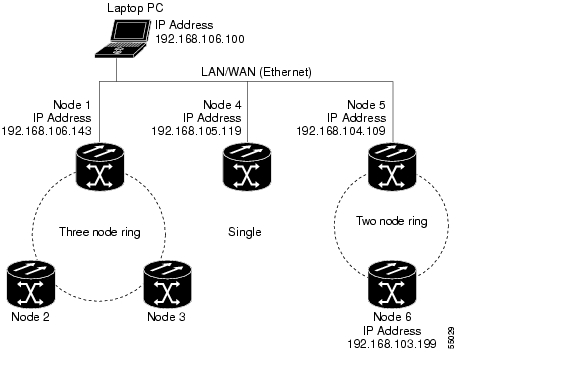
The next time you log into an ONS 15454, the login node group will be available in the Additional Nodes list of the Login dialog box. For example, in Figure 2-2, a login node group is created that contains the IP addresses for Nodes 1, 4, and 5. During login, if you choose this group from the Additional Nodes list and Disable Network Discovery is not selected, all nodes in the figure appear. If the login group and Disable Network Discovery are both selected, only Nodes 1, 4, and 5 appear. You can create as many login node groups as you need. The groups are stored in the CTC preferences file and are not visible to other users.

Figure 2-2 Login Node Group

Step 6 Return to your originating procedure (NTP).


DLP-G49 Add a Node to the Current Session or Login Group

Purpose

This task adds a node to the current CTC session or login node group.

Tools

None

Prerequisite Procedures

G46 Log into CTC

Required/As Needed

As needed

Onsite/Remote

Onsite or remote

Security Level

Provisioning or higher


Step 1 In any CTC view, from the CTC File menu, click Add Node.

Step 2 In the Add Node dialog box, enter the node name (or IP address).

Step 3 If you want to add the node to the current login node group, check Add to current login node group. Otherwise, leave it unchecked.


Note This check box is active only if you selected a login group when you logged into CTC.


Step 4 Click OK.

After a few seconds, the new node appears on the network view map.

Step 5 Return to your originating procedure (NTP).


DLP-G50 Delete a Node from the Current Session or Login Group

Purpose

This task removes a node from the current CTC session or login node group. To remove a node from a login node group that is not the current one, see "DLP-G51 Delete a Node from a Specific Login Node Group" task.

Tools

None

Prerequisite Procedures

G46 Log into CTC

Required/As Needed

As needed

Onsite/Remote

Onsite or remote

Security Level

Provisioning or higher


Step 1 From the CTC View menu, choose Go to Network View.

Step 2 On the network map, single-click the node that you want to delete.

Step 3 From the CTC File menu, click Delete Selected Node.

After a few seconds, the node disappears from the network view map.

Step 4 Return to your originating procedure (NTP).


DLP-G51 Delete a Node from a Specific Login Node Group

Purpose

This task removes a node from a specific login node group. To remove a node from the current login node group, see the "DLP-G50 Delete a Node from the Current Session or Login Group" task.

Tools

None

Prerequisite Procedures

G46 Log into CTC

Required/As Needed

As needed

Onsite/Remote

Onsite or remote

Security Level

Provisioning or higher


Step 1 In any CTC view, from the CTC Edit menu, choose Preferences.

Step 2 In the Preferences dialog box, click the Login Node Groups tab.

Step 3 Click the login node group tab containing the node you want to remove.

Step 4 Click the node you want to remove, then click Remove.

Step 5 Click OK.

Step 6 Return to your originating procedure (NTP).


DLP-G53 Configure the CTC Alerts Dialog Box for Automatic Popup

Purpose

This task sets up the CTC Alerts dialog box to open for all alerts, for circuit deletion errors only, or never. The CTC Alerts dialog box displays network disconnection, Send-PDIP inconsistency, circuit deletion status, condition retrieval errors, and software download failure.

Tools

None

Prerequisite Procedures

G46 Log into CTC

Required/As Needed

As needed

Onsite/Remote

Onsite or remote

Security Level

Provisioning or higher


Step 1 Click the CTC Alerts toolbar icon. (The icon is located on the far right of the CTC toolbar.)

Step 2 In the CTC Alerts dialog box, choose one of the following:

All alerts—Sets the CTC Alerts dialog box to open automatically for all notifications.

Error alerts only—Sets the CTC Alerts dialog box to open automatically for circuit deletion errors only.

Never—Sets the CTC Alerts dialog box to never open automatically.

Step 3 Click Close.

Step 4 Return to your originating procedure (NTP).


hometocprevnextglossaryfeedbacksearchhelp

Posted: Thu Sep 13 00:30:16 PDT 2007
All contents are Copyright © 1992--2007 Cisco Systems, Inc. All rights reserved.
Important Notices and Privacy Statement.