|
|

Table Of Contents
NTP-G63 Document Existing Provisioning
NTP-G64 View Alarms, History, Events, and Conditions
DLP-G116 View Alarm or Event History
DLP-G117 Change the Maximum Number of Session Entries for Alarm History
DLP-G118 Display Alarms and Conditions Using Time Zone
NTP-G65 Delete Cleared Alarms from Display
NTP-G66 View Alarm-Affected Circuits
NTP-G67 View Alarm Counts on the LCD for a Node, Slot, or Port
NTP-G68 Create, Download, and Assign Alarm Severity Profiles
DLP-G121 Create a New or Cloned Alarm Severity Profile
DLP-G122 Download an Alarm Severity Profile
DLP-G123 Apply Alarm Profiles to Ports
DLP-G124 Apply Alarm Profiles to Cards and Nodes
DLP-G125 Delete Alarm Severity Profiles
NTP-G69 Enable, Modify, or Disable Alarm Severity Filtering
DLP-G126 Enable Alarm Filtering
DLP-G127 Modify Alarm, Condition, and History Filtering Parameters
DLP-G128 Disable Alarm Filtering
NTP-G70 Suppress Alarms or Discontinue Alarm Suppression
DLP-G129 Suppress Alarm Reporting
DLP-G130 Discontinue Alarm Suppression
NTP-G72 Provision External Alarms and Controls on the Alarm Interface Controller-International Card
Manage Alarms
Note
The terms "Unidirectional Path Switched Ring" and "UPSR" may appear in Cisco literature. These terms do not refer to using Cisco ONS 15xxx products in a unidirectional path switched ring configuration. Rather, these terms, as well as "Path Protected Mesh Network" and "PPMN," refer generally to Cisco's path protection feature, which may be used in any topological network configuration. Cisco does not recommend using its path protection feature in any particular topological network configuration.
This chapter contains the procedures for viewing and managing the alarms and conditions on a Cisco ONS 15454.
Cisco Transport Controller (CTC) detects and reports alarms generated by the Cisco ONS 15454 and the Optical Networking System (ONS) network. You can use CTC to monitor and manage alarms at card, node, or network level. You can also view alarm counts on the LCD front panel.
Note
Before You Begin
This section lists the chapter procedures (NTPs). Turn to a procedure for applicable tasks (DLPs).
1.
2.
3.
4.
5.
6.
7.
8.
9.
NTP-G63 Document Existing Provisioning
Step 1
Step 2
Step 3
Stop. You have completed this procedure.
DLP-G113 Print CTC Data
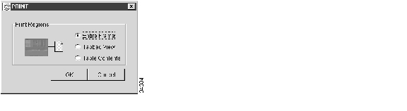
Step 1
The print operation is available for all network, node, and card view windows.
Step 2
Figure 8-1 Selecting CTC Data For Print
Step 3
•
•
•
–
–
–
–
–
–
–
–
–
–
–
–
The Table Contents option prints all the data contained in a table and the table column headings. For example, if you print the History window Table Contents view, you print all data included in the table whether or not items appear in the window.
Tip
Step 4
Step 5
Step 6
Step 7
DLP-G114 Export CTC Data
Step 1
Step 2
a.
b.
Note
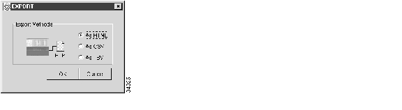
Step 3
Figure 8-2 Selecting CTC Data For Export
Step 4
•
•
•
Step 5
Text editor and word processor applications format the data exactly as it is exported, including comma or tab separators. All applications that open the data files allow you to format the data.
Step 6
Spreadsheet and database management programs also allow you to manage the exported data.
Note
The export operation applies to all tabular data except:
•
•
•
•
•
•
•
•
•
•
•
•
•
•
•
Step 7
Step 8
•
•
•
Step 9
Step 10
Step 11
Step 12
NTP-G64 View Alarms, History, Events, and Conditions
Step 1
Step 2
Step 3
Step 4
Step 5
Step 6
Step 7
Stop. You have completed this procedure.
DLP-G115 View Alarms
Step 1
Table 8-1 describes the columns in the Alarms window
Table 8-2 lists the color codes for alarm and condition severities.
Step 2
Step 3
DLP-G116 View Alarm or Event History
Step 1
Step 2
a.
b.
If you check the Alarms check box, the node alarm history appears. If you check the Events check box, the node Not Alarmed and transient event history appears. If you check both check boxes, you will retrieve node history for alarms and events.
c.
Note
Tip
Step 3
a.
b.
If you check the Alarms check box, the multishelf alarm history appears. If you check the Events check box, the multishelf Not Alarmed and transient event history appears. If you check both check boxes, you will retrieve the multishelf history for alarms and events.
c.
Step 4
a.
b.
If you check the Alarms check box, the shelf alarm history appears. If you check the Events check box, the shelf Not Alarmed and transient event history appears. If you check both check boxes, you will retrieve the shelf node history for alarms and events.
c.
Step 5
a.
b.
Alarms and conditions (events) raised during the current session appear.
Step 6
a.
b.
c.
d.
e.
If you check the Alarms check box, the node's alarm history appears. If you check the Events check box, the Not Alarmed and transient event history appears. If you check both boxes, node history for both alarms and events appears.
Note
Raised and cleared alarm messages (and events, if selected) appear.
Step 7
DLP-G117 Change the Maximum Number of Session Entries for Alarm History
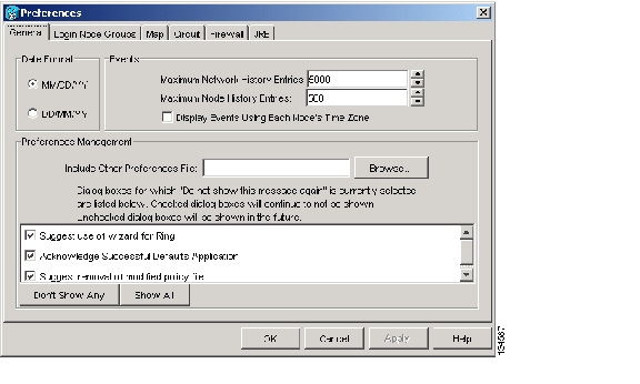
Step 1
The CTC Preferences dialog box appears ( Figure 8-3).
Figure 8-3 CTC Preferences Dialog Box
Step 2
Step 3
Note
Note
Step 4
DLP-G118 Display Alarms and Conditions Using Time Zone
Step 1
The CTC Preferences dialog box appears ( Figure 8-3).
Step 2
Step 3
Step 4
DLP-G119 Synchronize Alarms
Step 1
Step 2
This button causes CTC to retrieve a current alarm summary for the card, node, or network. This step is optional because CTC updates the Alarms window automatically as raise/clear messages arrive from the node.
Note
Step 3
DLP-G120 View Conditions
Step 1
Step 2
The Retrieve button requests the current set of fault conditions from the node, card, or network. The window is not updated when events change on the node. You must click Retrieve to see any changes.
Conditions include all fault conditions raised on the node, whether or not they are reported.
Note
Events that are reported as Major (MJ), Minor (MN), or Critical (CR) severities are alarms. Events that are reported as Not Alarmed (NA) are conditions. Conditions that are not reported at all are marked Not Reported (NR) in the Conditions window severity column.
Conditions that have a default severity of Critical (CR), Major (MJ), Minor (MN), or Not Alarmed (NA) but are not reported due to exclusion or suppression are shown as NR in the Conditions window.
Note
Current conditions are shown with the severity chosen in the alarm profile, if used. For more information about alarm profiles, see the "G68 Create, Download, and Assign Alarm Severity Profiles" procedure.
Note
Step 3
An exclusion rule eliminates all lower-level alarms or conditions that originate from the same cause. For example, a fiber break might cause a loss of signal (LOS) alarm, an alarm indication signal (AIS) condition, and a signal fail (SF) condition. If you check the Exclude Same Root Cause check box, only the LOS alarm will appear. According to Telcordia, exclusion rules apply to a query of "all conditions from a node."
Step 4
NTP-G65 Delete Cleared Alarms from Display
Step 1
Step 2
a.
b.
–
–
This action removes any cleared ONS 15454 alarms from the Alarms tab. The rows of cleared alarms turn white and have a C in their status (ST) column.
Step 3
a.
b.
–
–
Step 4
a.
b.
–
–
Step 5
Stop. You have completed this procedure.
NTP-G66 View Alarm-Affected Circuits
Step 1
Step 2
Note
The Select Affected Circuit option appears on the shortcut menu.
Step 3
The Circuits window appears with the affected OCHNC highlighted.
Stop. You have completed this procedure.
NTP-G67 View Alarm Counts on the LCD for a Node, Slot, or Port
Step 1
Step 2
Step 3
Step 4
Step 5
Step 6
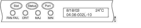
Figure 8-4 shows the shelf LCD panel.
Figure 8-4 Shelf LCD Panel
To return to the previous view from the Port screen, continue to press Port until the display cycles through all the ports on the slot.
To return to the node menu from the Slot screen, press Slot until you cycle through all the slots and see "Node."
If you do not press any buttons, the LCD will return to its default display with the node name. However, if you did not cycle through the options to return to the node status, you will see the slot or port where you last checked status.
Note
Stop. You have completed this procedure.
NTP-G68 Create, Download, and Assign Alarm Severity Profiles
Step 1
Step 2
Step 3
Note
Step 4
Step 5
Stop. You have completed this procedure.
DLP-G121 Create a New or Cloned Alarm Severity Profile
Step 1
Step 2
Note
Step 3
Step 4
a.
b.
Step 5
a.
b.
c.
Note
Step 6
The alarm severity profile appears in the Alarm Profiles window. The alarm profile list contains a master list of alarms that is used for a mixed node network. Some of these alarms might not be used in all ONS nodes.
Step 7
Step 8
Tip
Step 9
Profile names must be unique. If you try to import or name a profile that has the same name as another profile, CTC adds a suffix to create a new name. Long file names are supported.
Step 10
A new alarm profile (named in Step 9) is created. (If this is the first alarm profile created during installation, the default alarm profile settings are displayed in the AlarmType::Condition column on the left.) This profile duplicates the default profile severities and appears at the right of the previous profile column in the Alarm Profiles window. You can select it and drag it to a different position.
Note
The Default profile sets severities to standard Telcordia GR-474-CORE settings. If an alarm has an Inherited profile, it inherits (copies) its severity from the same alarm's severity at the higher level. For example, if you choose the Inherited profile from the network view, the severities at the lower levels (node, card, and port) will be copied from this selection. A card with an Inherited alarm profile copies the severities used by the node that contains the card. (If you are creating profiles, you can apply these separately at any level. To do this, refer to the "DLP-G124 Apply Alarm Profiles to Cards and Nodes" task.)
Step 11
a.
b.
c.
•
•
•
Step 12
Step 13
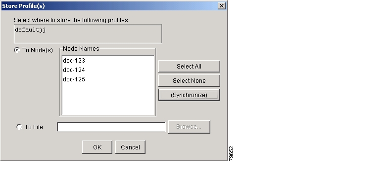
Step 14
Figure 8-5 Store Profiles Dialog Box
a.
•
•
•
•
•
•
b.
•
•
•
•
Step 15
•
•
•
Step 16
DLP-G122 Download an Alarm Severity Profile
Note
Step 1
Note
Step 2
Step 3
a.
b.
c.
Step 4
a.
b.
c.
Note
Step 5
The downloaded profile appears at the right side of the Alarm Profiles window.
Step 6
Step 7
Step 8
a.
•
•
•
•
•
b.
Step 9
DLP-G123 Apply Alarm Profiles to Ports
Purpose
This task applies a custom or default alarm severity profile to a port or ports.
Tools/Equipment
None
Prerequisite Procedures
G121 Create a New or Cloned Alarm Severity Profile
Required/As Needed
As needed
Onsite/Remote
Onsite or remote
Security Level
Provisioning or higher
Note
Step 1
Note
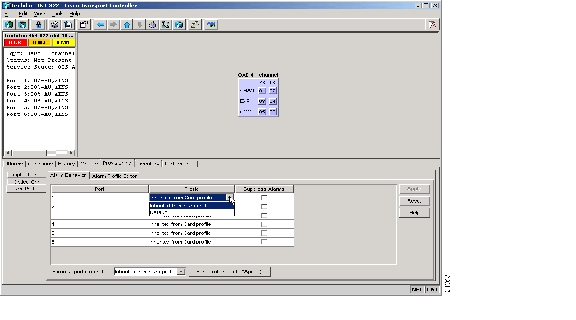
Step 2
Figure 8-6 shows alarm profiles for the AD-1C card, for example. CTC shows Parent Card Profile: Inherited.
Figure 8-6 AD-1C Card Alarm Profile
Go to Step 3 to apply profiles to a port. Go to Step 4 to apply profiles to all ports on a card.
Step 3
a.
b.
c.
Step 4
a.
b.
c.
d.
In node view, the Port Level Profiles column indicates port-level profiles with a notation such as "exist (1)".
Step 5
Step 6
DLP-G124 Apply Alarm Profiles to Cards and Nodes
Purpose
This task applies a custom or default alarm profile to cards or nodes.
Tools/Equipment
None
Prerequisite Procedures
G121 Create a New or Cloned Alarm Severity Profile
Required/As Needed
As needed
Onsite/Remote
Onsite or remote
Security Level
Provisioning or higher
Step 1
Step 2
a.
b.
c.
Step 3
a.
b.
c.
Step 4
Step 5
DLP-G125 Delete Alarm Severity Profiles
Step 1
Note
Step 2
Step 3
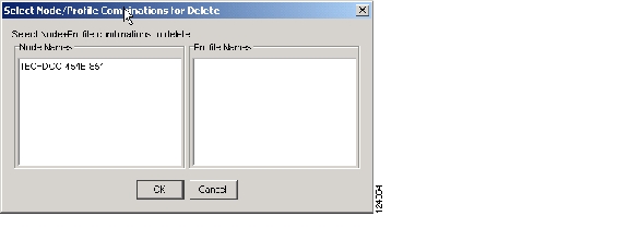
The Select Node/Profile Combination for Delete dialog box appears ( Figure 8-7).
Figure 8-7 Select Node/Profile Combination For Delete Dialog Box
Note
Note
Step 4
Tip
Step 5
Step 6
Step 7
If you delete a profile from a node, it still appears in the network view Provisioning > Alarm Profile Editor window unless you remove it using the following step.
Step 8
If a node and profile combination is selected but does not exist, a warning appears: "One or more of the profiles selected do not exist on one or more of the node(s) selected." For example, if Node A has only Profile 1 stored and the user tries to delete both Profile 1 and Profile 2 from Node A, this warning appears. However, the operation still removes Profile 1 from Node A.
The Default and Inherited special profiles cannot be deleted and do not appear in the Select Node/Profile Combination for Delete window.
Step 9
NTP-G69 Enable, Modify, or Disable Alarm Severity Filtering
Step 1
Step 2
Step 3
Step 4
Stop. You have completed this procedure.
DLP-G126 Enable Alarm Filtering
Step 1
Step 2
Note
Alarm filtering is enabled if the tool is selected and disabled if the tool is raised (not selected).
Alarm filtering is enabled in the card, node, and network views of the same window for all nodes in the network. For example, if the Filter tool is enabled in the node view Alarms window, the network view Alarms window and card view Alarms window also show the tool enabled.
Step 3
Step 4
Step 5
DLP-G127 Modify Alarm, Condition, and History Filtering Parameters
Step 1
Step 2
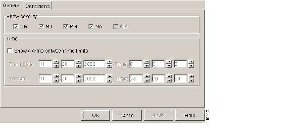
The filter dialog box appears, displaying the General tab. Figure 8-8 shows the Alarm Filter dialog box; the Conditions and History tabs have similar dialog boxes.
Figure 8-8 Alarm Filter Dialog Box General Tab
In the General tab Show Severity area, you can choose which alarm severities will show through the alarm filter and provision a time period during which filtered alarms show through the filter. To change the alarm severities shown in the filter, go to Step 3. To change the time period filter for the alarms, go to Step 4.
Step 3
When alarm filtering is disabled, all alarms show.
Step 4
To modify filter parameters for conditions, continue with Step 5. If you do not need to modify them, continue with Step 6.
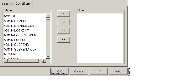
Step 5
Figure 8-9 Alarm Filter Dialog Box Conditions Tab
When filtering is enabled, conditions in the Show list are visible and conditions in the Hide list are invisible.
•
•
•
•
Note
Step 6
Alarm and condition filtering parameters are enforced when alarm filtering is enabled (see the "DLP-G126 Enable Alarm Filtering" task), and the parameters are not enforced when alarm filtering is disabled (see the "DLP-G128 Disable Alarm Filtering" task).
Step 7
DLP-G128 Disable Alarm Filtering
Step 1
Step 2
Note
Alarm filtering is enabled if the tool is indented (the filter icon is blue) and disabled if the tool is raised (not selected; the filter icon is white).
Step 3
Step 4
Step 5
NTP-G70 Suppress Alarms or Discontinue Alarm Suppression
Step 1
Step 2
Suppressing one or more alarms prevents them from appearing in Alarm or History windows or in any other clients. The suppress command causes CTC to display them in the Conditions window with their severity, their severity color code, and their service-affecting status.
Step 3
Stop. You have completed this procedure.
DLP-G129 Suppress Alarm Reporting
Caution
Note
Step 1
Step 2
a.
b.
All raised alarms for the node will change color to white in the Alarms window and their status will change to cleared. After suppressing alarms, clicking Synchronize in the Alarms window will remove cleared alarms from the window. However, an AS-CMD alarm will show in node or card view to indicate that node-level alarms were suppressed, and the word System will appear in the Object column.
Note
Step 3
a.
b.
Alarms that directly apply to this card will change appearance as described in Step 2. For example, if you suppressed raised alarms for an OC-48 card in Slot 16, raised alarms for this card will change in node or card view. The AS-CMD alarm will show the slot number in the Object number. For example, if you suppressed alarms for a Slot 16 OC-48 card, the AS-CMD object will be "SLOT-16."
Click Apply.
Step 4
Step 5
Step 6
Step 7
Alarms that apply directly to this port will change appearance as described in Step 2. (However, alarms raised on the entire card will remain raised.) A raised AS-CMD alarm that shows the port as its object will appear in either alarm window. For example, if you suppressed alarms for Port 1 on the Slot 16 OC-48 card, the alarm object will show "FAC-16-1."
Step 8
DLP-G130 Discontinue Alarm Suppression
Caution
Step 1
a.
b.
Suppressed alarms will reappear in the Alarms window. (They might have previously been cleared from the window using the Synchronize button.) The AS-CMD alarm with the System object will be cleared in all views.
Step 2
a.
b.
c.
d.
Suppressed alarms will reappear in the Alarms window. (They might have previously been cleared from the window using the Synchronize button.) The AS-CMD alarm with the slot object (for example, SLOT-16) will be cleared in all views.
Step 3
Step 4
Step 5
Suppressed alarms will reappear in the Alarms window. (They might have previously been cleared from the window using the Synchronize button.) The AS-CMD alarm with the port object (for example, FAC-16-1) will be cleared in all views.
Step 6
NTP-G72 Provision External Alarms and Controls on the Alarm Interface Controller-International Card
Note
Note
Step 1
a.
b.
Step 2
a.
b.
Step 3
Step 4
Step 5
Step 6
Step 7
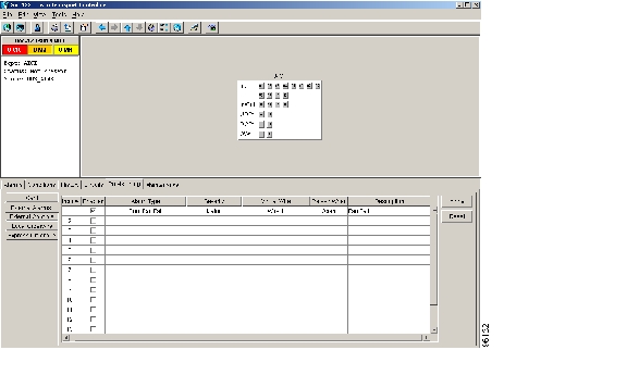
Step 8
Figure 8-10 Provisioning External Alarms on the AIC-I Card
Step 9
•
•
•
The severity determines the alarm's severity in the Alarms and History tabs and determines whether the LEDs are activated. Critical (CR), Major (MJ), and Minor (MN) alarms activate the LEDs. Not Alarmed (NA) and Not Reported (NR) events do not activate LEDs, but do report the information in CTC.
•
•
•
Step 10
Step 11
When you provision an external alarm, the alarm object is ENV-IN-nn. The variable nn refers to the external alarm's number, regardless of the name you assign.
Step 12
•
•
•
•
Step 13
Step 14
Note
Stop. You have completed this procedure.
![]()
![]()
![]()
![]()
![]()
![]()
![]()
![]()
Posted: Thu Sep 13 00:33:14 PDT 2007
All contents are Copyright © 1992--2007 Cisco Systems, Inc. All rights reserved.
Important Notices and Privacy Statement.