|
|

Table Of Contents
NTP-G76 Verify Optical Span Loss Using CTC
NTP-G77 Manage Automatic Power Control
DLP-G157 Disable Automatic Power Control
DLP-G158 Enable Automatic Power Control
DLP-G159 Refresh Automatic Power Control Information
NTP-G78 View ROADM Node Power Equalization
NTP-G80 Change Node Management Information
DLP-G160 Change the Node Name, Date, Time, and Contact Information
DLP-G161 Change the Login Legal Disclaimer
NTP-G134 Modify OSI Provisioning
DLP-G284 Modify the TARP Operating Parameters
DLP-G286 Remove a Static TID to NSAP Entry from the TARP Data Cache
DLP-G287 Add a TARP Manual Adjacency Table Entry
DLP-G292 Remove a TARP Manual Adjacency Table Entry
DLP-G293 Change the OSI Routing Mode
DLP-G294 Edit the OSI Router Configuration
DLP-G295 Edit the OSI Subnetwork Point of Attachment
DLP-G296 Edit an IP-Over-CLNS Tunnel
DLP-G297 Delete an IP-Over-CLNS Tunnel
NTP-G81 Change CTC Network Access
DLP-G266 Modify Backplane Port IP Settings in Security Mode
DLP-G267 Disable Node Security Mode
DLP-G163 Modify a Static Route
DLP-G164 Delete a Static Route
DLP-G166 Delete a Proxy Tunnel
DLP-G167 Delete a Firewall Tunnel
NTP-G82 Customize the CTC Network View
DLP-G168 Change the Network View Background Color
DLP-G169 Change the Default Network View Background Map
DLP-G170 Apply a Custom Network View Background Map
DLP-G173 Enable Dialog Box Do-Not-Display Option
DLP-G174 Switch Between TDM and DWDM Network Views
DLP-G330 Consolidate Links in Network View
NTP-G83 Modify or Delete Card Protection Settings
DLP-G175 Modify a Y-Cable Protection Group
DLP-G176 Modify a Splitter Protection Group
DLP-G177 Delete a Y-Cable Protection Group
NTP-G84 Initiate and Clear Y-Cable and Splitter External Switching Commands
DLP-G178 Apply a Manual Y-Cable or Splitter Protection Switch
DLP-G179 Apply a Force Y-Cable or Splitter Protection Switch
DLP-G180 Clear a Manual or Force Y-Cable or Splitter Protection Switch
DLP-G183 Clear a Lock-On or Lockout
NTP-G85 Modify or Delete OSC Terminations, GCC Terminations, and Provisionable Patchcords
DLP-G184 Change a GCC Termination
DLP-G185 Delete a GCC Termination
DLP-G186 Delete an OSC Termination
DLP-G187 Delete a Provisionable Patchcord
NTP-G86 Convert a Pass-Through Connection to Add/Drop Connections
NTP-G87 Change Node Timing Parameters
NTP-G88 Modify Users and Change Security
DLP-G188 Change Security Policy for a Single Node
DLP-G189 Change Security Policy for Multiple Nodes
DLP-G317 Change Node Access and PM Clearing Privilege
DLP-G328 Grant Superuser Privileges to a Provisioning User
DLP-G191 Change User Password and Security Level on a Single Node
DLP-G192 Change User Password and Security Level for Multiple Nodes
DLP-G193 Delete a User From a Single Node
DLP-G194 Delete a User From Multiple Nodes
DLP-G195 Log Out a User on a Single Node
DLP-G196 Log Out a User on Multiple Nodes
DLP-G281 Configure the Node for RADIUS Authentication
DLP-G282 View and Terminate Active Logins
NTP-G131 Convert DWDM Nodes to Hybrid Nodes
DLP-G197 Modify SNMP Trap Destinations
DLP-G198 Delete SNMP Trap Destinations
Manage the Node
This chapter explains how to modify node provisioning for the Cisco ONS 15454 and perform common management tasks such as monitoring the dense wavelength division multiplexing (DWDM) automatic power control (APC) and span loss values. To provision a new node, see Chapter 3, "Turn Up a Node." To change default network element (NE) settings and to view a list of those settings, refer to the "Network Element Defaults" appendix in the Cisco ONS 15454 DWDM Reference Manual.
Note
Unless otherwise specified, "ONS 15454" refers to both ANSI and ETSI shelf assemblies.
Before You Begin
Before performing the following procedures, investigate all alarms and clear any trouble conditions. Refer to the Cisco ONS 15454 DWDM Troubleshooting Guide as necessary.
This section lists the chapter procedures (NTPs). Turn to a procedure for applicable tasks (DLPs).
1.
2.
3.
4.
5.
6.
7.
8.
9.
10.
11.
12.
13.
14.
15.
NTP-G76 Verify Optical Span Loss Using CTC
Purpose
This procedure verifies the span loss between two DWDM nodes using Cisco Transport Controller (CTC). Perform this procedure after a node or network modification has occurred and you want to verify that the span loss between the nodes has not changed.
Tools/Equipment
None
Prerequisite Procedures
All procedures in "Turn Up a Network."
Required/As Needed
As needed
Onsite/Remote
Onsite or remote
Security Level
Superuser
Note
Step 1
Step 2
Step 3
Step 4
Step 5
•
•
•
•
Note
•
–
–
Step 6
Stop. You have completed this procedure.
NTP-G77 Manage Automatic Power Control
Step 1
Step 2
•
•
•
Stop. You have completed this procedure.
DLP-G157 Disable Automatic Power Control
Purpose
This task disables the DWDM APC.
Tools/Equipment
None
Prerequisite Procedures
Required/As Needed
As needed
Onsite/Remote
Onsite or remote
Security Level
Superuser
Caution
Step 1
Step 2
Step 3
Step 4
Step 5
DLP-G158 Enable Automatic Power Control
Purpose
This task enables the DWDM APC.
Tools/Equipment
None
Prerequisite Procedures
Required/As Needed
As needed
Onsite/Remote
Onsite or remote
Security Level
Superuser
Caution
Step 1
Step 2
Step 3
Step 4
Step 5
DLP-G159 Refresh Automatic Power Control Information
Step 1
Step 2
Step 3
NTP-G78 View ROADM Node Power Equalization
Step 1
Step 2
Step 3
•
•
•
Note
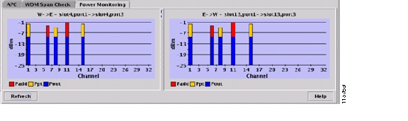
Figure 10-1 shows an example of ROADM node with equalized output power.
Figure 10-1 Equalized ROADM Power Example
Step 4
Stop. You have completed this procedure.
NTP-G80 Change Node Management Information
Purpose
This procedure changes the node name, date, time, contact information, and login legal disclaimer.
Tools/Equipment
None
Prerequisite Procedures
NTP-G24 Set Up Name, Date, Time, and Contact Information, page 3-10
Required/As Needed
As needed
Onsite/Remote
Onsite or remote
Security Level
Provisioning or higher
Step 1
Step 2
Step 3
Step 4
Step 5
Step 6
Stop. You have completed this procedure.
DLP-G160 Change the Node Name, Date, Time, and Contact Information
Caution
Step 1
Step 2
•
•
•
•
•
Note
•
•
•
•
•
•
•
•
See the "NTP-G24 Set Up Name, Date, Time, and Contact Information" procedure on page 3-10 for detailed field descriptions.
Step 3
Step 4
DLP-G161 Change the Login Legal Disclaimer
Step 1
Step 2
Step 3
Step 4
Step 5
NTP-G134 Modify OSI Provisioning
Note
Step 1
Step 2
Step 3
•
•
•
•
•
•
•
•
•
•
Step 4
Stop. You have completed this procedure.
DLP-G284 Modify the TARP Operating Parameters
Step 1
Step 2
•
Note
•
Note
•
–
–
–
Note
•
Note
•
Note
•
Note
•
•
•
Note
•
•
•
•
•
•
Note
Step 3
Step 4
DLP-G286 Remove a Static TID to NSAP Entry from the TARP Data Cache
Step 1
Step 2
Step 3
Step 4
Step 5
DLP-G287 Add a TARP Manual Adjacency Table Entry
Step 1
Step 2
Step 3
•
–
–
•
Step 4
Step 5
DLP-G292 Remove a TARP Manual Adjacency Table Entry
Purpose
This task removes an entry from the TARP MAT.
Tools/Equipment
None
Prerequisite Procedures
Required/As Needed
As needed
Onsite/Remote
Onsite or remote
Security Level
Provisioning or higher
Caution
Step 1
Step 2
Step 3
Step 4
Step 5
DLP-G293 Change the OSI Routing Mode
Purpose
This task changes the OSI routing mode.
Tools/Equipment
None
Prerequisite Procedures
Required/As Needed
As needed
Onsite/Remote
Onsite or remote
Security Level
Provisioning or higher
Caution
Caution
Caution
Step 1
•
•
•
Step 2
Step 3
•
•
•
–
–
Note
Step 4
•
•
Step 5
DLP-G294 Edit the OSI Router Configuration
Step 1
Step 2
Step 3
a.
Note
b.
c.
d.
Step 4
DLP-G295 Edit the OSI Subnetwork Point of Attachment
Step 1
Step 2
Step 3
Step 4
•
•
•
Note
Step 5
Step 6
DLP-G296 Edit an IP-Over-CLNS Tunnel
Purpose
This task allows you to edit the parameters of an IP-over-CLNS tunnel.
Tools/Equipment
None
Prerequisite Procedures
DLP-G291 Create an IP-Over-CLNS Tunnel, page 3-36
Required/As Needed
As needed
Onsite/Remote
Onsite or remote
Security Level
Provisioning or higher
Caution
Step 1
Step 2
Step 3
•
–
–
The Cisco proprietary tunnel is slightly more efficient than the GRE tunnel because it does not add the GRE header to each IP packet. The two tunnel types are not compatible. Most Cisco routers support the Cisco IP tunnel, while only a few support both GRE and Cisco IP tunnels. You generally should create Cisco IP tunnels if you are tunneling between two Cisco routers or between a Cisco router and an ONS node.
Caution
•
•
•
•
Step 4
Step 5
DLP-G297 Delete an IP-Over-CLNS Tunnel
Caution
Step 1
Step 2
Step 3
Step 4
Step 5
NTP-G81 Change CTC Network Access
Note
Step 1
Step 2
Step 3
•
•
•
•
Step 4
Stop. You have completed this procedure.
DLP-G162 Change IP Settings
Caution
Step 1
Step 2
•
•
•
•
•
•
Gateway Settings
•
–
–
–
See the "DLP-G56 Provision IP Settings" task on page 3-14 for detailed field descriptions.
Step 3
If you changed a network field that will cause the node to reboot, such as the IP address, or subnet mask, the Change Network Configuration confirmation dialog box appears. If you changed a gateway setting, a confirmation appropriate to the gateway field appears.
Step 4
If you changed an IP address, subnet mask length, both ONS 15454 TCC2/TCC2P cards reboot, one at a time. A TCC2/TCC2P card reboot causes a temporary loss of connectivity to the node, but traffic is unaffected.
Step 5
Step 6
DLP-G265 Lock Node Security
Caution
Note
Step 1
Step 2
Step 3
Step 4
DLP-G266 Modify Backplane Port IP Settings in Security Mode
Purpose
This task modifies the ONS 15454 backplane IP address, subnet mask, and default router when security mode is enabled. It also modifies settings that control backplane IP address visibility in CTC and the ONS 15454 LCD.
Tools/Equipment
TCC2P cards must be installed.
Prerequisite Procedures
NTP-G103 Back Up the Database, page 13-2
Required/As Needed
As needed
Onsite/Remote
Onsite or remote
Security Level
Superuser
Caution
Caution
Note
Step 1
Step 2
•
•
•
•
–
–
–
•
Step 3
If you changed the IP address, subnet mask, or default router, the node will reboot. This will take 5 to 10 minutes.
Step 4
DLP-G267 Disable Node Security Mode
Note
Note
Note
Note
Step 1
Step 2
Step 3
Step 4
•
•
•
Step 5
Step 6
•
•
•
Step 7
Within the next 30 to 40 seconds, the TCC2P cards reboot. CTC switches to network view, and the CTC Alerts dialog box appears. In network view, the node changes to gray and a DISCONNECTED condition appears.
Step 8
Step 9
DLP-G163 Modify a Static Route
Step 1
Step 2
Step 3
Step 4
Step 5
•
•
•
See the "DLP-G58 Create a Static Route" task on page 3-20 for detailed field descriptions.
Step 6
Step 7
DLP-G164 Delete a Static Route
Step 1
Step 2
Step 3
Step 4
Step 5
DLP-G165 Disable OSPF
Purpose
This task disables the OSPF routing protocol process for an ONS 15454 LAN.
Tools/Equipment
None
Prerequisite Procedures
DLP-G59 Set Up or Change Open Shortest Path First Protocol, page 3-21
Required/As Needed
As needed
Onsite/Remote
Onsite or remote
Security Level
Provisioning or higher
Step 1
Step 2
Step 3
Step 4
DLP-G166 Delete a Proxy Tunnel
Purpose
This task removes a proxy tunnel.
Tools/Equipment
None
Prerequisite Procedures
DLP-G97 Provision a Proxy Tunnel, page 7-24
Required/As Needed
As needed
Onsite/Remote
Onsite or remote
Security Level
Superuser
Step 1
Step 2
Step 3
Step 4
DLP-G167 Delete a Firewall Tunnel
Purpose
This task removes a firewall tunnel.
Tools/Equipment
None
Prerequisite Procedures
DLP-G98 Provision a Firewall Tunnel, page 7-25
Required/As Needed
As needed
Onsite/Remote
Onsite or remote
Security Level
Superuser
Step 1
Step 2
Step 3
Step 4
NTP-G82 Customize the CTC Network View
Step 1
Step 2
•
•
•
•
•
•
Stop. You have completed this procedure.
DLP-G168 Change the Network View Background Color
Note
Step 1
Step 2
Step 3
Step 4
Step 5
Step 6
DLP-G169 Change the Default Network View Background Map
Purpose
This task changes the default map of the CTC network view.
Tools/Equipment
None
Prerequisite Procedures
Required/As Needed
As needed
Onsite/Remote
Onsite or remote
Security Level
Superuser
Note
Step 1
Step 2
Step 3
Step 4
Step 5
Step 6
Step 7
Step 8
Step 9
Step 10
Step 11
Step 12
Step 13
Step 14
DLP-G170 Apply a Custom Network View Background Map
Note
Step 1
Step 2
Step 3
Step 4
Step 5
Step 6
Step 7
Step 8
Step 9
Step 10
DLP-G171 Create Domain Icons
Note
Step 1
Step 2
Step 3
Step 4
Step 5
DLP-G172 Manage Domain Icons
Note
Step 1
Step 2
Step 3
DLP-G173 Enable Dialog Box Do-Not-Display Option
Note
Step 1
Step 2
The Preferences Management area field lists all dialog boxes where "Do not show this message again" is enabled.
Step 3
•
•
Step 4
Step 5
DLP-G174 Switch Between TDM and DWDM Network Views
Step 1
Step 2
•
•
•
Step 3
DLP-G330 Consolidate Links in Network View
Note
Step 1
Step 2
•
•
•
•
•
•
•
Step 3
Step 4
a.
b.
c.
d.
Step 5
a.
b.
Note
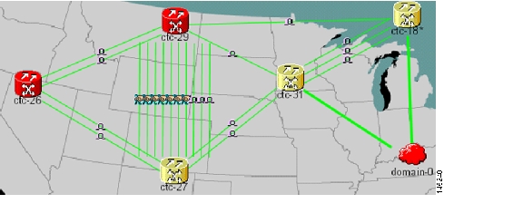
Figure 10-2 shows the network view with unconsolidated DCC and PPC links.
Figure 10-2 Unconsolidated Links in the Network View
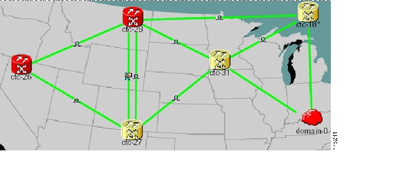
Figure 10-3 shows a network view with globally consolidated links.
Figure 10-3 Consolidated Links in the Network View
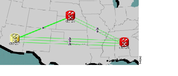
Figure 10-4 shows a network view with local DCC link consolidation between two nodes.
Figure 10-4 Network View with Local Link Consolidation
Step 6
Step 7
a.
b.
Step 8
Step 9
a.
The link classes that appear in the Link Filter dialog are determined by the Network Scope you choose in the network view ( Table 10-3).
Table 10-3 Link Classes By Network Scope
ALL
DCC, GCC, OTS, PPC, Server Trail
DWDM
GCC, OTS, PPC
TDM
DCC, PPC
b.
c.
Step 10
NTP-G83 Modify or Delete Card Protection Settings
Caution
Step 1
Step 2
•
•
•
Step 3
Stop. You have completed this procedure.
DLP-G175 Modify a Y-Cable Protection Group
Purpose
This task modifies a Y-cable protection group that has been created for two TXP or MXP card client ports.
Tools/Equipment
None
Prerequisite Procedures
G33 Create a Y-Cable Protection Group
Required/As Needed
As needed
Onsite/Remote
Onsite or remote
Security Level
Provisioning or higher
Step 1
Step 2
Step 3
Step 4
•
•
•
Step 5
Step 6
DLP-G176 Modify a Splitter Protection Group
Step 1
Step 2
Step 3
Step 4
•
•
•
Step 5
Step 6
DLP-G177 Delete a Y-Cable Protection Group
Purpose
This task deletes a Y-cable protection group.
Tools/Equipment
None
Prerequisite Procedures
Required/As Needed
As needed
Onsite/Remote
Onsite or remote
Security Level
Provisioning or higher
Step 1
Step 2
Step 3
Step 4
Step 5
NTP-G84 Initiate and Clear Y-Cable and Splitter External Switching Commands
Purpose
This procedure describes how to apply and remove Manual and Force protection switches on Y-cable and splitter protection groups. It also describes how to apply and remove a Lock On or Lock Out protection command to a Y-cable protection group.
Tools/Equipment
None
Prerequisite Procedures
NTP-G32 Install the Transponder and Muxponder Cards, page 3-51
Required/As Needed
As needed
Onsite/Remote
Onsite
Security Level
Superuser
Note
Step 1
Step 2
Step 3
Step 4
Step 5
Step 6
Step 7
Stop. You have completed this procedure.
DLP-G178 Apply a Manual Y-Cable or Splitter Protection Switch
Caution
Step 1
Step 2
Step 3
Step 4
Step 5
If conditions permit, the Manual switch will be applied. To clear the Manual switch, see the "DLP-G180 Clear a Manual or Force Y-Cable or Splitter Protection Switch" task.
Step 6
DLP-G179 Apply a Force Y-Cable or Splitter Protection Switch
Caution
Step 1
Step 2
Step 3
Step 4
Step 5
The Force switch will be applied. To clear the Force switch, see the "DLP-G180 Clear a Manual or Force Y-Cable or Splitter Protection Switch" task.
Step 6
DLP-G180 Clear a Manual or Force Y-Cable or Splitter Protection Switch
Purpose
This task clears a Manual or Force protection switch on a Y-cable or splitter protection group.
Tools/Equipment
None
Prerequisite Procedures
One of the following tasks:
•
Required/As Needed
As needed
Onsite/Remote
Both
Security Level
Maintenance or higher
Step 1
Step 2
Step 3
Step 4
Step 5
The Manual or Force protection switch is cleared.
Step 6
DLP-G181 Apply a Lock-On
Note
Step 1
Step 2
Step 3
Step 4
Step 5
The lock-on has been applied. Traffic cannot switch to the protect card. To clear the lock-on, see the "DLP-G183 Clear a Lock-On or Lockout" task.
Note
Step 6
DLP-G182 Apply a Lockout
Note
Step 1
Step 2
Step 3
Step 4
Step 5
The lockout has been applied. Traffic cannot switch to the protect card. To clear the lockout, see the "DLP-G183 Clear a Lock-On or Lockout" task.
Note
Step 6
DLP-G183 Clear a Lock-On or Lockout
Step 1
Step 2
Step 3
Step 4
Step 5
The lock-on or lockout is cleared.
Step 6
NTP-G85 Modify or Delete OSC Terminations, GCC Terminations, and Provisionable Patchcords
Purpose
This procedure modifies GCC terminations, and deletes provisionable patchcords, OSC terminations, and GCC terminations.
Tools/Equipment
None
Prerequisite Procedures
One or more of the following tasks:
•
•
Required/As Needed
As needed
Onsite/Remote
Onsite or remote
Security Level
Provisioning or higher
Caution
Step 1
Step 2
•
•
•
•
Stop. You have completed this procedure.
DLP-G184 Change a GCC Termination
Step 1
Step 2
Step 3
Step 4
•
•
•
•
Step 5
Step 6
DLP-G185 Delete a GCC Termination
Note
Step 1
Step 2
Step 3
Step 4
Step 5
Step 6
DLP-G186 Delete an OSC Termination
Caution
Step 1
Step 2
a.
b.
Step 3
Step 4
Until all network OSC terminations are deleted, loss of signal (LOS) or power failure alarms might appear on the OPT-BST amplifier, OSCM card, and OSC-CSM card.
Step 5
DLP-G187 Delete a Provisionable Patchcord
Purpose
This task deletes a provisionable patchcord.
Tools/Equipment
None
Prerequisite Procedures
Required/As Needed
As needed
Onsite/Remote
Onsite or remote
Security Level
Provisioning and higher
Step 1
Step 2
Step 3
Step 4
Step 5
NTP-G86 Convert a Pass-Through Connection to Add/Drop Connections
Step 1
Step 2
Step 3
•
•
Step 4
Step 5
a.
b.
c.
Step 6
Step 7
Step 8
Note
Step 9
a.
b.
c.
d.
Stop. You have completed this procedure.
NTP-G87 Change Node Timing Parameters
Purpose
This procedure changes the timing parameters for the ONS 15454. To switch the timing reference, see the "NTP-G112 Change the Node Timing Reference" procedure on page 13-17.
Tools/Equipment
None
Prerequisite Procedures
Required/As Needed
As needed
Onsite/Remote
Onsite or remote
Security Level
Provisioning or higher
Caution
Step 1
Step 2
Step 3
Step 4
•
Note
•
•
•
•
See the "NTP-G53 Set Up Timing" task for field descriptions.
Step 5
Note
•
•
•
Step 6
Step 7
Note
•
•
•
•
•
•
Step 8
•
•
•
•
Step 9
Caution
Step 10
Stop. You have completed this procedure.
NTP-G88 Modify Users and Change Security
Step 1
Step 2
Step 3
•
•
•
•
•
•
•
•
•
•
•
•
Step 4
Stop. You have completed this procedure.
DLP-G188 Change Security Policy for a Single Node
Step 1
Step 2
Step 3
•
•
•
Note
Step 4
•
•
•
•
Step 5
•
•
Step 6
•
•
Step 7
Step 8
DLP-G189 Change Security Policy for Multiple Nodes
Step 1
Step 2
Step 3
Step 4
Step 5
•
•
•
Note
Step 6
•
•
•
•
Step 7
•
•
Step 8
•
•
Step 9
Step 10
Step 11
Step 12
DLP-G317 Change Node Access and PM Clearing Privilege
Step 1
Step 2
•
–
–
–
–
•
Step 3
•
•
•
Step 4
Step 5
Step 6
Step 7
Step 8
•
•
•
Step 9
Step 10
Step 11
DLP-G328 Grant Superuser Privileges to a Provisioning User
Step 1
Step 2
Step 3
•
•
•
•
Step 4
Note
Step 5
A pencil icon will appear next to the default name that will be changed as a result of editing the defaults file.
Step 6
DLP-G191 Change User Password and Security Level on a Single Node
Purpose
This task changes settings for an existing user at one node.
Tools/Equipment
None
Prerequisite Procedures
Required/As Needed
As needed
Onsite/Remote
Onsite or remote
Security Level
Superuser
Note
Step 1
Step 2
Step 3
•
•
•
•
•
See the "DLP-G54 Create a New User on a Single Node" procedure on page 3-8 for field descriptions.
Step 4
Step 5
Note
Step 6
DLP-G192 Change User Password and Security Level for Multiple Nodes
Note
Step 1
Step 2
Step 3
Step 4
•
•
•
•
•
See the "DLP-G55 Create a New User on Multiple Nodes" task on page 3-9 for field descriptions.
Step 5
Note
Step 6
Step 7
Step 8
DLP-G193 Delete a User From a Single Node
Purpose
This task deletes an existing user from a single node.
Tools/Equipment
None
Prerequisite Procedures
Required/As Needed
As needed
Onsite/Remote
Onsite or remote
Security Level
Superuser
Note
Note
Step 1
Step 2
Step 3
Step 4
Step 5
Step 6
Step 7
DLP-G194 Delete a User From Multiple Nodes
Purpose
This task deletes an existing user from multiple nodes.
Tools/Equipment
None
Prerequisite Procedures
Required/As Needed
As needed
Onsite/Remote
Onsite or remote
Security Level
Superuser
Note
Note
Step 1
Step 2
Step 3
Step 4
Note
Step 5
Step 6
Step 7
DLP-G195 Log Out a User on a Single Node
Purpose
This task logs out a user from a single node.
Tools/Equipment
None
Prerequisite Procedures
Required/As Needed
As needed
Onsite/Remote
Onsite or remote
Security Level
Superuser
Step 1
Step 2
Step 3
Step 4
Step 5
Step 6
DLP-G196 Log Out a User on Multiple Nodes
Purpose
This task logs out a user from multiple nodes.
Tools/Equipment
None
Prerequisite Procedures
Required/As Needed
As needed
Onsite/Remote
Onsite or remote
Security Level
Superuser
Step 1
Step 2
Step 3
Step 4
Step 5
Step 6
Step 7
Step 8
Step 9
Step 10
DLP-G281 Configure the Node for RADIUS Authentication
Caution
Note
shell:priv-lvl=N
where N is equal to:
•
•
•
•
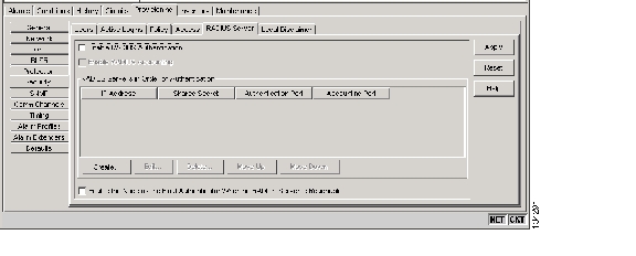
Step 1
Figure 10-5 RADIUS Server Tab
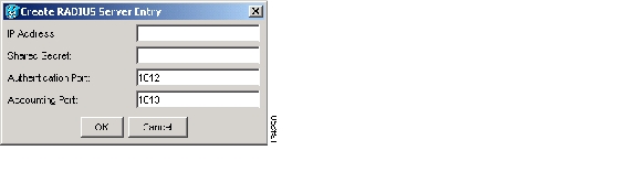
Step 2
Figure 10-6 Create RADIUS Server Entry Window
Step 3
The GNE passes authentication requests from the ENEs in its network to the RADIUS server, which grants authentication if the GNE is listed as a client on the server.
Caution
Step 4
Step 5
Step 6
Step 7
Note
Step 8
Step 9
Step 10
Step 11
Step 12
Step 13
Step 14
Step 15
DLP-G282 View and Terminate Active Logins
Step 1
•
•
•
•
•
•
Step 2
Step 3
Step 4
NTP-G131 Convert DWDM Nodes to Hybrid Nodes
Note
Note
Step 1
Step 2
Step 3
a.
b.
c.
d.
Step 4
Step 5
a.
b.
c.
Step 6
Step 7
a.
b.
c.
d.
Step 8
a.
b.
The card name disappears and the slot turns gray.
Step 9
Step 10
Note
a.
b.
c.
d.
e.
Note
Step 11
Note
a.
a.
b.
c.
Step 12
Note
a.
b.
c.
d.
Step 13
a.
a.
b.
Step 14
Step 15
a.
b.
c.
Step 16
Step 17
a.
b.
c.
d.
Step 18
Step 19
Step 20
Stop. You have completed this procedure.
NTP-G89 Change SNMP Settings
Step 1
Step 2
Step 3
•
•
Step 4
Stop. You have completed this procedure.
DLP-G197 Modify SNMP Trap Destinations
Step 1
Step 2
For a description of SNMP traps, refer to the Cisco ONS 15454 DWDM Reference Manual.
Step 3
The community name is a form of authentication and access control. The community name assigned to the ONS 15454 is case-sensitive and must match the community name of the network management system (NMS).
Step 4
Step 5
Refer to your NMS documentation to determine whether to use SNMPv1 or SNMPv2.
Step 6
Step 7
Step 8
Step 9
Step 10
DLP-G198 Delete SNMP Trap Destinations
Step 1
Step 2
Step 3
Step 4
Step 5
![]()
![]()
![]()
![]()
![]()
![]()
![]()
![]()
Posted: Thu Sep 13 00:37:28 PDT 2007
All contents are Copyright © 1992--2007 Cisco Systems, Inc. All rights reserved.
Important Notices and Privacy Statement.