|
|

Table Of Contents
Manage the Cisco MetroPlanner Window
GUI Information and Shortcuts
This appendix describes the Cisco MetroPlanner views, menus, tools, and shortcuts options. For more information about Cisco MetroPlanner, refer to Chapter 1, "Overview."
Manage the Cisco MetroPlanner Window
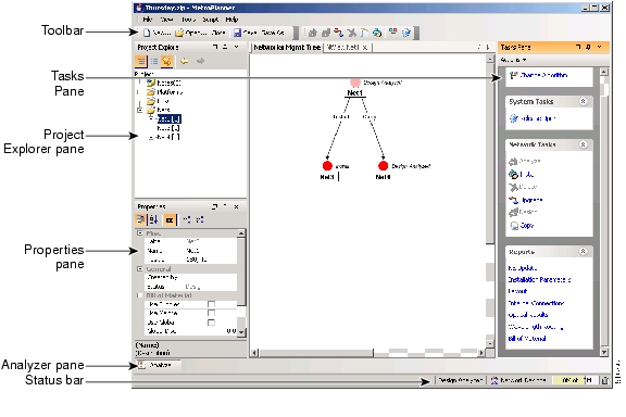
The Cisco MetroPlanner window provides a menu bar, toolbar, a Project Explorer pane, a Properties pane, an Analyzer pane, and a Task Pane to allow you to manage a network design ( Figure A-1). The Networks Mgmt Tree tab displays the networks that you have created for a project. The NtVw Net# tab displays the sites for a network (identified by the Net# on the tab).
Figure A-1 Cisco MetroPlanner Window with Network Tree
Menu and Toolbar Options
The Cisco MetroPlanner window menu bar and toolbar provide primary Cisco MetroPlanner functions. Table A-1 shows the actions that are available from the menu and toolbar.
Table A-1 Menu and Toolbar Options
File
New
Creates a new Cisco MetroPlanner project. See the "2.3 Creating a Project" section on page 2-21.
Open
Opens an existing Cisco MetroPlanner project. See the "2.1.1 Opening a Project" section on page 2-3.
Close
Closes the current project without closing the Cisco MetroPlanner session. If you have not saved the current project, Cisco MetroPlanner will prompt you to save before closing. See the "2.1.5 Closing a Project" section on page 2-5.
Save
Saves the current project. See the "2.1.3 Saving a Project" section on page 2-4.
Save As
Allows you to save the current project with a new file name. See the "2.1.3 Saving a Project" section on page 2-4.
Clear History
—
Clears the file history from Cisco MetroPlanner. Cisco MetroPlanner maintains a list of the last ten open projects in the File menu.
Exit
—
Exits the Cisco MetroPlanner software.
View
My Default Layout
—
Changes the Cisco MetroPlanner display to the user default layout. Cisco MetroPlanner allows you to define the default value for Platform Options, Project Options, and General Options. The defined value are used as default for each new created project. See the "2.2 Setting Cisco MetroPlanner Options" section on page 2-5.
Default Layout
—
Returns the Cisco MetroPlanner display to the system default layout.
Tasks Pane
—
Displays the commands available for the selected entity (network, site, duct, etc.).
Project Explorer
—
Displays the Project Explorer pane, which includes folders for project notes, networks, sites, fibers, traffic demand groups, subnets, maintenance centers, restricted equipment list, and reports. Clicking the plus (+) sign by each folder expands the folder. Clicking the minus (-) sign by each folder hides the folder. contents. You can also right-click a folder and choose Expand from the shortcut menu to show folder contents. The default location of the Project Explorer pane is the upper left section of the Cisco MetroPlanner window.
Properties
—
Displays the Properties pane, which shows parameter settings for the selected entity in the Project Explorer, Networks Mgmt Tree tab, or NtVw Net# tab. The default location of the Properties pane is the lower left section of the Cisco MetroPlanner window.
Analyzer Messages
—
Displays the Analyzer Messages pane at the bottom of the Cisco MetroPlanner window. The Analyzer Messages pane displays any error messages that occur during network analysis.
Tools
Options
—
Opens the Options Explorer dialog box, where you can change the user default settings. See the "2.2 Setting Cisco MetroPlanner Options" section on page 2-5.
DB Parts Mgmt
—
Opens the PartsTreePanel dialog box, where you can view the list of available parts for each release. See the "2.2.4 Setting the Fiber Type Default Values" section on page 2-9.
Price List Mgmt
—
Opens the Price Manager dialog box, where you can view maintenance contracts and add price databases. See the "2.9 Managing the Price List" section on page 2-86.
Plug In
—
Opens the PlugIn Registry dialog box, which allows you to customize Cisco MetroPlanner with plug-ins released by Cisco. See the "2.2.10 Adding Plug-ins" section on page 2-18 and the "2.2.11 Managing Plug-ins" section on page 2-19.
Export
—
Opens the Export dialog box, which allows you to export user options, price lists, maintenance contracts, and parts database files. See the "2.2.7 Exporting a File" section on page 2-16.
Import
—
Opens the Import dialog box, which allows you to import user options, price lists, maintenance contracts, and parts database files. See the "2.2.8 Importing a File" section on page 2-17.
Script
Run Script
—
Opens the Choose a script to run dialog box, which allows you to run a script that Cisco provides. See the "2.2.13 Running a Script" section on page 2-21.
Help
Manual
—
Opens the Cisco MetroPlanner online help.
Tips Of The Day
—
Opens the Tip of the Day dialog box, which provides helpful hints about using Cisco MetroPlanner. Click the Next button to view the next tip and the Back button to view a previous tip. Check Show Tips on Startup to display the Tip of the Day dialog box when you launch Cisco MetroPlanner.
About
—
Displays Cisco MetroPlanner version information.
—
Create a new site
Opens the Site Creation wizard when you click this icon and then click in the Cisco MetroPlanner window. See the "2.3.1 Adding Sites" section on page 2-27.
—
Create a new duct
Allows you to create a new duct between sites. See the "2.3.3 Adding Fiber Spans" section on page 2-28.
—
Create a new P2P demand
Opens the Point to Point Demand Creation Wizard when you click this icon and then click two sites. See the "2.3.4 Creating a Point-to-Point Demand" section on page 2-29.
—
Create a new P-ring demand
Opens the P-Ring Creation Wizard. See the "2.3.5 Creating a Protected Ring Demand" section on page 2-31.
—
Zoom in
Zooms in on the NtVw Net# tab.
—
Zoom out
Zoom out from the NtVw Net# tab.
—
Normal viewing
Returns the NtVw Net# tab to normal viewing (1:1).
—
Fit to window
Resizes the view so that all sites fit inside the NtVw Net# tab window.
—
Analyze Network
Analyzes the selected network. See the "2.4 Analyzing the Network" section on page 2-36.
—
Enter design mode
Puts the selected Design-Analyzed network back into the design mode for further changes. See the "2.4 Analyzing the Network" section on page 2-36.
—
Put current network in upgrade mode
Creates a copy of the selected Design-Analyzed network in the Upgrade state. See the "2.7.3 Creating an Upgrade Network" section on page 2-79.
—
Delete current network
Deletes the selected network. See the "2.3.7 Deleting a Network" section on page 2-35.
—
Copy current network
Copies the selected network. See the "2.7.1 Creating a Copy of the Network" section on page 2-78.
—
Put current network in install mode
Creates a copy of the selected Design-Analyzed network in the Install state. See the "2.7.2 Creating a Network in the Install State" section on page 2-78.
—
Reports Diff
Opens the Reports Diff dialog box, which allows you to create a report that shows the differences between networks.
—
Run the Garbage Collector
Deletes unloaded networks from memory.
Cisco MetroPlanner Panes
Cisco MetroPlanner provides four panes that help you manage a network design: Project Explorer, Properties, Analysis, and Tasks Pane.
Project Explorer Pane
The Project Explorer pane provides a management tree for the entire project. Each network appears as a folder that contains the sites, fibers, traffic groups, subnets, maintenance centers, restricted equipment lists, and reports for that network. If you have made changes to a network design, that network folder and the changed item folder appear in blue italics in the pane.
By default, the Project Explorer pane is located in the upper left section of the Cisco MetroPlanner window. Table A-2 shows the actions that are available from the Project Explorer toolbar.
Properties Pane
The Properties pane shows all of the parameters set for a selected item (either in the Project Explorer, the Network Mgmt Tree tab, or the NtVw Net# tab). Many items are editable in the Properties pane. By default, the Properties pane is located in the lower left section of the Cisco MetroPlanner window.
Table A-3 shows the actions that are available from the Properties Pane toolbar.
Analyzer Pane
The Analyzer tab at the bottom of the Cisco MetroPlanner window appears after you have analyzed a network design. Clicking the Analyzer tab opens the Analyzer pane. Table A-5 shows the actions that are available from the Analyzer pane.
Tasks Pane
The Tasks Pane lists the available commands and reports for a selected item. The commands change based on the selected item. For example, a selected site will have different commands available than a selected fiber span. By default, the Tasks Pane is located in the upper right section of the Cisco MetroPlanner window. Table A-5 shows the actions that are available from the Tasks Pane toolbar.
Shortcuts
Cisco MetroPlanner provides the following mouse shortcuts:
•
Double-clicking a network icon in the Network Mgmt Tree tab opens the NtVw Net# tab, which shows the sites for that network.
•
•
Table A-6 Shortcut Menu Actions
Networks in the following states: Design, Install, and Upgrade
•
•
•
•
•
Analyzed networks
•
•
•
•
•
•
•
•
•
•
•
•
–
–
•
Sites
•
•
If the network is analyzed, the following actions are also available:
•
•
•
•
•
•
–
–
•
Fiber spans
•
If the network is analyzed, the Unlock command is also available. See the "2.7.4 Unlocking Parameters in the Network Design" section on page 2-80.
Traffic demands
•
•
•
If the network is analyzed, the Unlock command is also available. See the "2.7.4 Unlocking Parameters in the Network Design" section on page 2-80.
Site Icons
A site icon indicates the functionality of site. Table A-7 lists the site icons.
![]()
![]()
![]()
![]()
![]()
![]()
![]()
![]()
Posted: Wed Jun 21 00:27:08 PDT 2006
All contents are Copyright © 1992--2006 Cisco Systems, Inc. All rights reserved.
Important Notices and Privacy Statement.