|
|

Table Of Contents
3.1 Supported Cisco MetroPlanner Topologies
Modeled Network Examples
This chapter provides examples of typical optical networks you can model using Cisco MetroPlanner.
This chapter contains the following sections:
Supported Cisco MetroPlanner Topologies
3.1 Supported Cisco MetroPlanner Topologies
Cisco MetroPlanner supports the following topologies:
•
Bus (single span, point-to-point, and linear)
•
•
An example of each topology is given in this chapter.
3.2 Bus Topologies
Bus topologies comprise three types of topologies: single span, point-to-point, and linear.
3.2.1 Single-Span Topology
Figure 3-1 shows an example of a single-span topology. Single-span topologies are characterized by a single span link. The single-span configuration only supports two terminal sites (full terminal or flexible channel-count terminal) without any intermediate line amplifier or optical add/drop multiplexing (OADM) sites.
Figure 3-1 Single-Span Topology Example
3.2.2 Point-to-Point Topology
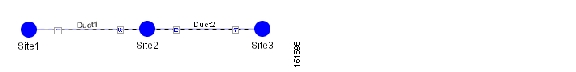
Figure 3-2 shows an example of a point-to-point topology. In a point-to-point topology, all the wavelengths are terminated at the same point in the chain. In the point-to-point configuration, no channels are added or dropped in intermediate sites.
Figure 3-2 Point-to-Point Topology Example
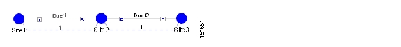
3.2.3 Linear Topology
Figure 3-3 shows an example of a linear topology. Linear configurations are characterized by the presence of two terminal sites (full terminal or flexible channel-count terminal). Between the two terminal sites, OADM or line amplifiers nodes can be inserted. In a linear configuration, specific wavelengths are terminated at different points in the chain and only unprotected traffic can be provisioned.
Figure 3-3 Linear Topology Example
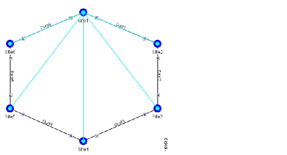
3.3 Hubbed Ring Topology
Figure 3-4 shows an example of a hubbed ring topology. In this configuration, at least one of the sites must be a hub site, where all channels are terminated.
Figure 3-4 Hubbed Ring Topology Example
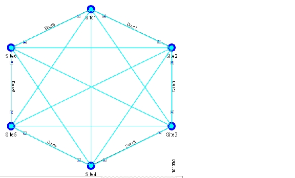
3.4 Meshed Topology
Figure 3-5 provides an example of a meshed ring topology. A meshed ring is characterized by the absence of a hub node.
Figure 3-5 Meshed Ring Topology Example
![]()
![]()
![]()
![]()
![]()
![]()
![]()
![]()
Posted: Wed Jun 21 00:08:41 PDT 2006
All contents are Copyright © 1992--2006 Cisco Systems, Inc. All rights reserved.
Important Notices and Privacy Statement.