|
|

Table Of Contents
5.1.2 Card and Fan-Tray Assembly Power Requirements
5.2.1 E100T-12 Card-Level Indicators
5.2.2 E100T-12 Port-Level Indicators
5.2.4 E100T-12 Card Specifications
5.3.1 E100T-G Card-Level Indicators
5.3.2 E100T-G Port-Level Indicators
5.3.4 E100T-G Card Specifications
5.4.1 E1000-2 Card-Level Indicators
5.4.2 E1000-2 Port-Level Indicators
5.4.4 E1000-2 Card Specifications
5.5.1 E1000-2-G Card-Level Indicators
5.5.2 E1000-2-G Port-Level Indicators
5.5.4 E1000-2-G Card Specifications
5.6.1 G1000-4 Card-Level Indicators
5.6.2 G1000-4 Port-Level Indicators
5.6.4 G1000-4 Card Specifications
Ethernet Cards
The Cisco ONS 15454 integrates Ethernet into a SONET time-division multiplexing (TDM) platform. This chapter describes the G series Ethernet card and E series Ethernet cards. For Ethernet application information, see Chapter 12, "Ethernet Operation." For installation and card turn-up procedures, refer to the Cisco ONS 15454 Procedure Guide.
Chapter topics include:
5.1 Card Overview
The card overview section summarizes card functions, power consumption, temperature ranges, and compatibility.
Note
Each card is marked with a symbol that corresponds to a slot (or slots) on the ONS 15454 shelf assembly. The cards are then installed into slots displaying the same symbols. See the Cisco ONS 15454 Procedure Guide for a list of slots and symbols.
5.1.1 Ethernet Cards
Table 5-1 lists the Cisco ONS 15454 Ethernet cards.
Table 5-1 Ethernet Cards for the ONS 15454
The E100T-12 card provides 12 switched, autosensing, 10/100 Base-T Ethernet ports.
See the "E100T-12 Card" section
The E1000-2 card provides two ports of IEEE-compliant, 1000 Mbps ports.
See the "E1000-2 Card" section
The E100T-G card provides 12 switched, autosensing, 10/100 Base-T Ethernet ports and is compatible with the XC10G card.
See the "E100T-G Card" section
The E1000-2-G card provides two ports of IEEE-compliant, 1000 Mbps ports and is compatible with the XC10G card.
See the "E1000-2-G Card" section
The G1000-4 card provides four ports of IEEE-compliant, 1000 Mbps ports and is compatible with the XC10G card.
See the "G1000-4 Card" section
5.1.2 Card and Fan-Tray Assembly Power Requirements
Table 5-2 lists power requirements for individual cards.
Note
5.1.3 Card Temperature Ranges
Table 5-3 shows C-Temp and I-Temp compliant cards and their product names.
Note
5.2 E100T-12 Card
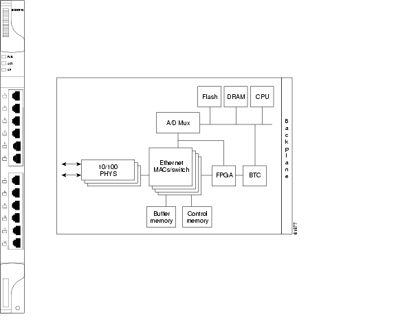
Do not use the E100T-12 when the XC10G cross-connect card is in use. The ONS 15454 uses E100T-12 cards for Ethernet (10 Mbps) and Fast Ethernet (100 Mbps). Each card provides 12 switched, IEEE 802.3-compliant, 10/100 Base-T Ethernet ports that can independently detect the speed of an attached device (auto-sense) and automatically connect at the appropriate speed. The ports auto-configure to operate at either half or full duplex and determine whether to enable or disable flow control. You can also configure Ethernet ports manually. Figure 5-1 shows the faceplate and a block diagram of the card.
Figure 5-1 E100T-12 faceplate and block diagram
The E100T-12 Ethernet card provides high-throughput, low-latency packet switching of Ethernet traffic across a SONET network while providing a greater degree of reliability through SONET "self-healing" protection services. This Ethernet capability enables network operators to provide multiple 10/100 Mbps access drops for high-capacity customer LAN interconnects, Internet traffic, and cable modem traffic aggregation. It enables the efficient transport and co-existence of traditional TDM traffic with packet-switched data traffic.
Each E100T-12 card supports standards-based, wire-speed, layer 2 Ethernet switching between its Ethernet interfaces. The 802.1Q tag logically isolates traffic (typically subscribers). 802.1Q also supports multiple classes of service.
You can install the E100T-12 card in any multispeed slot. Multiple Ethernet cards installed in an ONS 15454 can act independently or as a single Ethernet switch. You can create logical SONET ports by provisioning a number of STS channels to the packet switch entity within the ONS 15454. Logical ports can be created with a bandwidth granularity of STS-1. The ONS 15454 supports STS-1, STS-3c, STS-6c, or STS-12c circuit sizes.
Note
5.2.1 E100T-12 Card-Level Indicators
The E100T-12 card faceplate has two card-level LED indicators.
5.2.2 E100T-12 Port-Level Indicators
The E100T-12 card also has 12 pairs of LEDs (one pair for each port) to indicate port conditions. You can find the status of the E100T-12 card port using the LCD screen on the ONS 15454 fan-tray assembly. Use the LCD to view the status of any port or card slot; the screen displays the number and severity of alarms for a given port or slot.
Table 5-5 E100T-12 Port-Level Indicators
Transmitting and Receiving
Idle and Link Integrity
Inactive Connection or Unidirectional Traffic
5.2.3 E100T-12 Compatibility
Do not use the E100T-12 card with the XC10G card. If you want to use the XC10G card, the E100T-G is compatible with the XC10G.
5.2.4 E100T-12 Card Specifications
•
–
C-Temp (15454-E100T): 0 to +55 degrees Celsius
–
–
•
–
–
–
–
•
–
5.3 E100T-G Card
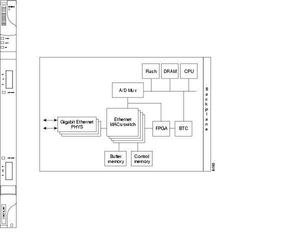
Use the E100T-G when the XC10G cross-connect card is in use. The ONS 15454 uses E100T-G cards for Ethernet (10 Mbps) and Fast Ethernet (100 Mbps). Each card provides 12 switched, IEEE 802.3-compliant, 10/100 Base-T Ethernet ports that can independently detect the speed of an attached device (auto-sense) and automatically connect at the appropriate speed. The ports auto-configure to operate at either half or full duplex and determine whether to enable or disable flow control. You can also configure Ethernet ports manually. Figure 5-2 shows the faceplate and a block diagram of the card.
Figure 5-2 E100T-G faceplate and block diagram
The E100T-G Ethernet card provides high-throughput, low-latency packet switching of Ethernet traffic across a SONET network while providing a greater degree of reliability through SONET "self-healing" protection services. This Ethernet capability enables network operators to provide multiple 10/100 Mbps access drops for high-capacity customer LAN interconnects, Internet traffic, and cable modem traffic aggregation. It enables the efficient transport and co-existence of traditional TDM traffic with packet-switched data traffic.
Each E100T-G card supports standards-based, wire-speed, layer 2 Ethernet switching between its Ethernet interfaces. The 802.1Q tag logically isolates traffic (typically subscribers). 802.1Q also supports multiple classes of service.
You can install the E100T-G card in any multispeed slot. Multiple Ethernet cards installed in an ONS 15454 can act independently or as a single Ethernet switch. You can create logical SONET ports by provisioning a number of STS channels to the packet switch entity within the ONS 15454. Logical ports can be created with a bandwidth granularity of STS-1. The ONS 15454 supports STS-1, STS-3c, STS-6c, or STS-12c circuit sizes.
Note
5.3.1 E100T-G Card-Level Indicators
The E100T-G card faceplate has two card-level LED indicators.
5.3.2 E100T-G Port-Level Indicators
The E100T-G card also has 12 pairs of LEDs (one pair for each port) to indicate port conditions. You can find the status of the E100T-G card port using the LCD screen on the ONS 15454 fan-tray assembly. Use the LCD to view the status of any port or card slot; the screen displays the number and severity of alarms for a given port or slot.
5.3.3 E100T-G Compatibility
Use the E100T-G when the XC10G cross-connect card is in use.
5.3.4 E100T-G Card Specifications
•
–
C-Temp (15454-E100T-G): 0 to +55 degrees Celsius
–
–
•
–
–
•
–
5.4 E1000-2 Card
Do not use the E1000-2 when the XC10G cross-connect card is in use. The ONS 15454 uses E1000-2 cards for Gigabit Ethernet (1000 Mbps). The E1000-2 card provides two IEEE-compliant, 1000 Mbps ports for high-capacity customer LAN interconnections. Each port supports full-duplex operation. Figure 5-3 shows the card faceplate and a block diagram of the card.
The E1000-2 card uses standard Cisco gigabit interface converter (GBIC) modular receptacles for the optical ports. GBICs are hot-swappable input/output devices that plug into a Gigabit Ethernet port to link the port to the fiber-optic network. Cisco provides two GBIC models: one for short-reach applications and one for long-reach applications. The short-reach model connects to multimode fiber and the long-reach model requires single-mode fiber.
For Software R2.2.0 and later, both GBIC modules are offered as separate orderable products: an IEEE 1000Base-SX compliant, 850 nm optical module and an IEEE 1000Base-LX-compliant, 1300 nm optical module, the 850 nm SX optics are designed for multimode fiber and distances of up to 220 meters on 62.5 micron fiber and up to 550 meters on 50 micron fiber. For more information see the Cisco ONS 15454 Procedure Guide.
Figure 5-3 E1000-2 faceplate and block diagram
The E1000-2 Gigabit Ethernet card provides high-throughput, low-latency packet switching of Ethernet traffic across a SONET network while providing a greater degree of reliability through SONET "self-healing" protection services. This enables network operators to provide multiple 1000 Mbps access drops for high-capacity customer LAN interconnects. It enables efficient transport and co-existence of traditional TDM traffic with packet-switched data traffic.
Each E1000-2 card supports standards-based, layer 2 Ethernet switching between its Ethernet interfaces and SONET interfaces on the ONS 15454. The 802.1Q VLAN tag logically isolates traffic (typically subscribers). The E1000-2 supports two 802.1Q.
You can install the E1000-2 card into any multispeed slot. Multiple Ethernet cards installed in an ONS 15454 can act together as a single switching entity or as an independent single switch supporting a variety of SONET port configurations.
You can create logical SONET ports by provisioning STS channels to the packet switch entity within the ONS 15454. Logical ports can be created with a bandwidth granularity of STS-1. The ONS 15454 supports STS-1, STS-3c, STS-6c, or STS-12c circuit sizes.
Note
5.4.1 E1000-2 Card-Level Indicators
The E1000-2 card faceplate has two card-level LED indicators.
5.4.2 E1000-2 Port-Level Indicators
The E1000-2 card also has one bicolor LED per port. When the green LINK LED is on, carrier is detected, meaning an active network cable is installed. When the green LINK LED is off, an active network cable is not plugged into the port, or the card is carrying unidirectional traffic. The amber port ACT LED flashes at a rate proportional to the level of traffic being received and transmitted over the port.
Table 5-9 E1000-2 Port-Level Indicators
Transmitting and Receiving
Idle and Link Integrity
Inactive Connection or Unidirectional Traffic
5.4.3 E1000-2 Compatibility
Do not use the E1000-2 card with the XC10G card. If you want to use the XC10G card, the E1000-2-G is compatible with the XC10G.
5.4.4 E1000-2 Card Specifications
•
–
C-Temp (15454-E1000-2): 0 to +55 degrees Celsius
–
–
•
–
–
–
–
•
–
–
5.5 E1000-2-G Card
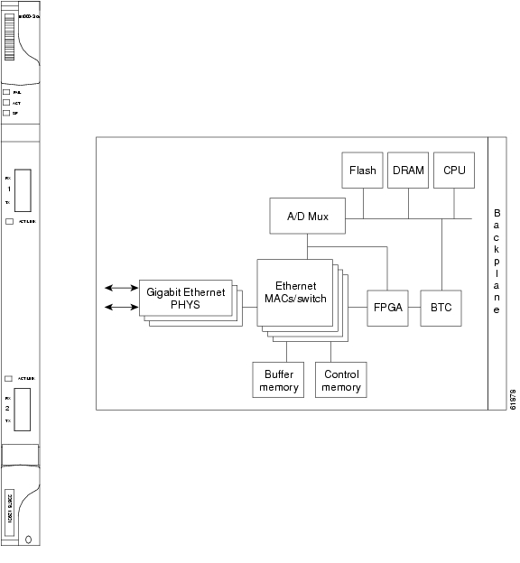
Use the E1000-2-G when the XC10G cross-connect card is in use. The ONS 15454 uses E1000-2-G cards for Gigabit Ethernet (1000 Mbps). The E1000-2-G card provides two IEEE-compliant, 1000 Mbps ports for high-capacity customer LAN interconnections. Each port supports full-duplex operation. Figure 5-4 shows the card faceplate and a block diagram of the card.
The E1000-2-G card uses standard Cisco gigabit interface converter (GBIC) modular receptacles for the optical ports. GBICs are hot-swappable input/output devices that plug into a Gigabit Ethernet port to link the port to the fiber-optic network. Cisco provides two GBIC models: one for short-reach applications and one for long-reach applications. The short-reach model connects to multimode fiber and the long-reach model requires single-mode fiber.
For Software R2.2.0 and later, both GBIC modules are offered as separate orderable products: an IEEE 1000Base-SX compliant, 850 nm optical module and an IEEE 1000Base-LX-compliant, 1300 nm optical module, the 850 nm SX optics are designed for multimode fiber and distances of up to 220 meters on 62.5 micron fiber and up to 550 meters on 50 micron fiber. For more information see the Cisco ONS 15454 Procedure Guide.
Figure 5-4 E1000-2-G faceplate and block diagram
The E1000-2-G Gigabit Ethernet card provides high-throughput, low-latency packet switching of Ethernet traffic across a SONET network while providing a greater degree of reliability through SONET "self-healing" protection services. This enables network operators to provide multiple 1000 Mbps access drops for high-capacity customer LAN interconnects. It enables efficient transport and co-existence of traditional TDM traffic with packet-switched data traffic.
Each E1000-2-G card supports standards-based, layer 2 Ethernet switching between its Ethernet interfaces and SONET interfaces on the ONS 15454. The 802.1Q VLAN tag logically isolates traffic (typically subscribers). The E1000-2-G supports two 802.1Q.
You can install the E1000-2-G card into any multispeed slot. Multiple Ethernet cards installed in an ONS 15454 can act together as a single switching entity or as an independent single switch supporting a variety of SONET port configurations.
You can create logical SONET ports by provisioning STS channels to the packet switch entity within the ONS 15454. Logical ports can be created with a bandwidth granularity of STS-1. The ONS 15454 supports STS-1, STS-3c, STS-6c, or STS-12c circuit sizes.
Note
5.5.1 E1000-2-G Card-Level Indicators
The E1000-2-G card faceplate has two card-level LED indicators.
5.5.2 E1000-2-G Port-Level Indicators
The E1000-2-G card also has one bicolor LED per port. When the green LINK LED is on, carrier is detected, meaning an active network cable is installed. When the green LINK LED is off, an active network cable is not plugged into the port, or the card is carrying unidirectional traffic. The amber port ACT LED flashes at a rate proportional to the level of traffic being received and transmitted over the port.
Table 5-11 E1000-2-G Port-Level Indicators
Transmitting and Receiving
Idle and Link Integrity
Inactive Connection or Unidirectional Traffic
5.5.3 E1000-2-G Compatibility
Use the E1000-2-G when the XC10G cross-connect card is in use.
5.5.4 E1000-2-G Card Specifications
•
–
C-Temp (15454-E1000-2-G): 0 to +55 degrees Celsius
–
–
•
–
–
–
–
•
–
–
5.6 G1000-4 Card
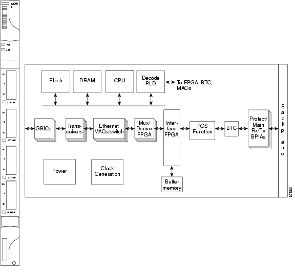
Use the G1000-4 card when the XC10G card is in use. The ONS 15454 uses G1000-4 cards for Gigabit Ethernet (1000 Mbps). The G1000-4 card provides four ports of IEEE-compliant, 1000 Mbps interfaces. Each port supports full-duplex operation for a maximum bandwidth of OC-48 on each card. The G1000-4 card uses GBIC modular receptacles for the optical interfaces.
Two GBIC modules are offered as separate orderable products for maximum customer flexibility:
•
•
•
The 850 nm SX optics are designed for multimode fiber and distances of up to 220 meters on 62.5 micron fiber and up to 550 meters on 50 micron fiber. The 1300 nm LX optics are designed for single-mode fiber and distances of up to ten kilometers. The 1550 nm ZX optics are designed for single-mode fiber and distances of up to eighty kilometers. Figure 5-5 shows the card faceplate and the block diagram of the card.
Figure 5-5 G1000-4 faceplate and block diagram
The G1000-4 Gigabit Ethernet card provides high-throughput, low latency transport of Ethernet encapsulated traffic (IP and other layer 2 or layer 3 protocols) across a SONET network. Carrier-class Ethernet transport is achieved by hitless (< 50 msec) performance in the event of any failures or protection switches (such as 1+1 APS, UPSR, or BLSR). Full provisioning support is possible via CTC, TL1, or CTM.
You can install the G1000-4 card into any multispeed slot for a total shelf capacity of 48 Gigabit Ethernet ports.
Note
The circuit sizes supported are STS-1, STS-3c, STS-6c, STS-9c, STS-24c, STS-48c.
5.6.1 G1000-4 Card-Level Indicators
The G1000-4 card faceplate has two card-level LED indicators.
5.6.2 G1000-4 Port-Level Indicators
The G1000-4 card also has one bicolor LED per port. The following table describes the status that each color represents.
5.6.3 G1000-4 Compatibility
The G1000-4 card requires Cisco ONS 15454 Release 3.2 or later system software and XC10G cross-connect cards.
5.6.4 G1000-4 Card Specifications
•
–
C-Temp (15454-G1000-4): 0 to +55 degrees Celsius–
–
•
–
–
–
–
![]()
![]()
![]()
![]()
![]()
![]()
![]()
![]()
Posted: Mon Feb 25 15:37:12 PST 2008
All contents are Copyright © 1992--2008 Cisco Systems, Inc. All rights reserved.
Important Notices and Privacy Statement.