|
|

Table Of Contents
6.1 Electrical Card Protection
6.2 Electrical Card Protection and the Backplane
6.2.2 High-Density BNC Protection
6.5 Inhibiting Protection Group Switching
Card Protection
This chapter explains the Cisco ONS 15454 card protection configurations. To provision card protection, refer to the Cisco ONS 15454 Procedure Guide.
Chapter topics include:
•
Electrical Card Protection and the Backplane
•
6.1 Electrical Card Protection
The ONS 15454 provides a variety of electrical card protection methods. This section describes the protection options. Figure 6-1 shows a 1:1 protection scheme and Figure 6-2 shows a 1:N protection scheme.
6.1.1 Protection, 1:1
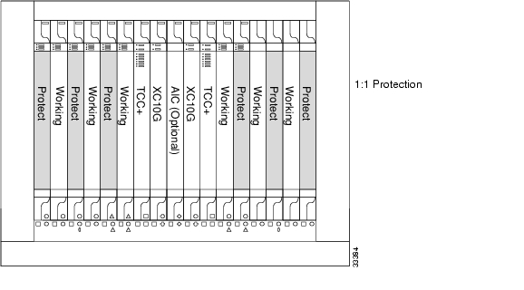
In 1:1 protection, a working card is paired with a protect card of the same type. If the working card fails, the traffic from the working card switches to the protect card. When the failure on the working card is resolved, traffic automatically reverts to the working card. Figure 6-1 shows the ONS 15454 in a 1:1 protection configuration. Each working card in an even-numbered slot is paired with a protect card in an odd-numbered slot: Slot 1 is protecting Slot 2, Slot 3 is protecting Slot 4, Slot 5 is protecting Slot 6, Slot 17 is protecting Slot 16, Slot 15 is protecting Slot 14, and Slot 13 is protecting Slot 12. The following electrical cards use a 1:1 protection scheme: EC1-12, DS1-14, DS3-12 and DS3-12E.
Figure 6-1 ONS 15454 cards in a 1:1 protection configuration
6.1.2 Protection, 1:N
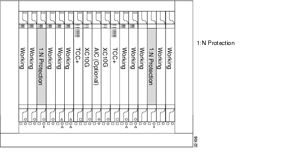
1:N protection allows a single card to protect up to five working cards of the same DS-N level. A DS1N-14 card protects DS1-14 cards, a DS3N-12 card protects DS3-12 cards, and DS3N-12E cards protect DS3-12E cards. The standard DS1-14, DS3-12, and DS3-12E cards provide 1:1 protection only. Currently, 1:N protection operates only at the DS-1 and DS-3 levels. 1:N cards have added circuitry to act as the protection card in a 1:N protection group. Otherwise, the card is identical to the standard card and can serve as a normal working card.
The physical DS-1 or DS-3 interfaces on the ONS 15454 backplane use the working card until the working card fails. When the node detects this failure, the protection card takes over the physical DS-1 or DS-3 electrical interfaces through the relays and signal bridging on the backplane. Figure 6-2 shows the ONS 15454 in a 1:N protection configuration. Each side of the shelf assembly has only one card protecting all of the cards on that side.
Figure 6-2 ONS 15454 cards in a 1:N protection configuration
6.1.2.1 Revertive Switching
1:N protection supports revertive switching. Revertive switching sends the electrical interfaces (traffic) back to the original working card after the card comes back online. Detecting an active working card triggers the reversion process. There is a variable time period for the lag between detection and reversion, called the revertive delay, which you can set using the ONS 15454 software, Cisco Transport Controller (CTC). To set the revertive delay, refer to the Cisco ONS 15454 Procedure Guide. All cards in a protection group share the same reversion settings. 1:N protection groups default to automatic reversion.
6.1.2.2 Protection Guidelines, 1:N
Several rules apply to 1:N protection groups in the ONS 15454:
•
•
•
The ONS 15454 supports 1:N equipment protection for all add-drop multiplexer configurations (ring, linear, and terminal), as specified by Telcordia GR-253-CORE.
The ONS 15454 automatically detects and identifies a 1:N protection card when the card is installed in Slot 3 or Slot 15. However, the slot containing the 1:N card in a protection group must be manually provisioned as a protect slot because by default all cards are working cards.
For detailed procedures on setting up DS-1 and DS-3 protection groups, refer to the Cisco ONS 15454 Procedure Guide.
6.2 Electrical Card Protection and the Backplane
Protection schemes for electrical cards differ slightly depending on the Electrical Interface Assembly (EIA) type used on the ONS 15454 backplane. The difference is due to the varying connector size. For example, because BNC connectors are larger, fewer DS3-12 cards can be supported when using a BNC connector.
Note
Caution
6.2.1 Standard BNC Protection
When you use BNC connectors, the ONS 15454 supports 1:1 protection or 1:N protection for a total of four working DS-3 electrical cards. If you are using EC-1 electrical cards with the BNC EIA, the ONS 15454 supports 1:1 protection and a total of four working cards. Slots 2, 4, 14, and 16 are designated working slots. These slots are mapped to a set of 12 BNC connectors on the EIA. These slots can be used without protection for unprotected DS-3 access.
With 1:N or 1:1 protection, Slots 1, 3, 15 and 17 are designated for protection when BNC connectors are used. With 1:N protection, Slots 3 and 15 are also designated for protection when BNC connectors are used. Slots 5, 6, 12, and 13 do not support DS3-12 cards when you use the regular BNC EIA.
6.2.2 High-Density BNC Protection
When you use the High-Density BNC EIA, the ONS 15454 supports 1:1 protection or 1:N protection for eight total working DS-3 electrical cards. If you are using EC-1 electrical cards with the High-Density BNC EIA, the ONS 15454 supports 1:1 protection and a total of eight working cards. Slots 1, 2, 4, 5, 13, 14, 16, and 17 are designated working slots.
These slots are mapped to a set of 12 BNC type connectors on the EIA. You can use these slots without protection for unprotected DS-3 or EC-1 access. Slots 3 and 15 are designated for 1:N protection slots when you use BNC connectors with the High-Density BNC EIA. Slots 6 and 12 do not support DS-3 or EC-1 cards when you use the High-Density BNC EIA.
6.2.3 SMB Protection
When you use SMB connectors, the ONS 15454 supports 1:1 or 1:N protection for the DS-1 and the DS-3 electrical cards. If you are using EC-1 cards with the SMB EIA, the ONS 15454 supports 1:1 protection. Working and protection electrical cards are defined by card slot pairs (the same card type is used for working and protect modules; the protection of the card is defined by the slot where it is housed). Each slot maps to a set of 12 or 14 SMB connectors on the EIA depending on the number of ports on the corresponding card. Any slot can be used without protection for unprotected DS-1, DS-3, or EC-1 access.
The DS1N-14 card can be a working or protect card in 1:1 or 1:N protection schemes. When used with 1:N protection, the DS1N-14 card can protect up to five DS1-14 plug-ins using the SMB connectors with the DS-1 electrical interface adapters (baluns).
6.2.4 AMP Champ Protection
When you use AMP Champ connectors, the ONS 15454 supports 1:1 or 1:N protection for the DS-1 cards. The DS1N-14 card can be a working or protect card in 1:1 or 1:N protection schemes. When used with 1:N protection, the DS1N-14 card can protect up to five DS1-14 plug-ins using the AMP Champ EIA.
6.3 Optical Card Protection
With 1+1 port-to-port protection, any number of ports on the protect card can be assigned to protect the corresponding ports on the working card. The working and protect cards do not have to be placed side by side in the node. A working card must be paired with a protect card of the same type, for example, an OC-3 card should be paired with another OC-3 card. The protection takes place on the port level, any number of ports on the protect card can be assigned to protect the corresponding ports on the working card.
For example, on a four-port card, you can assign one port as a protection port on the protect card (protecting the corresponding port on the working card) and leave three ports unprotected. Conversely, you can assign three ports as protection ports and leave one port unprotected.
Note
With 1:1 or 1:N protection (electrical cards), the protect card must protect an entire slot. In other words, all the ports on the protect card will be used in the protection scheme.
1+1 span protection can be either revertive or non-revertive. With non-revertive 1+1 protection, when a failure occurs and the signal switches from the working card to the protect card, the signal stays switched to the protect card until it is manually switched back. Revertive 1+1 protection automatically switches the signal back to the working card when the working card comes back online.
You create and modify protection schemes using CTC software. For more information, refer to the Cisco ONS 15454 Procedure Guide.
6.4 Unprotected Cards
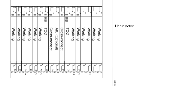
Unprotected cards are not included in a protection scheme; therefore, a card failure or a signal error results in lost data. Because no bandwidth lies in reserve for protection, unprotected schemes maximize the available ONS 15454 bandwidth. Figure 6-3 shows the ONS 15454 in an unprotected configuration. All cards are in a working state.
Figure 6-3 ONS 15454 in an unprotected configuration
6.5 Inhibiting Protection Group Switching
Protection group switching allows you to prohibit traffic from switching to a specified card using the Maintenance > Protection tabs. Protection group switching can be accomplished by applying a Lock On or a Lock Out to a specified card. When the Lock On state is applied to a specified working or protect card, any traffic which is currently on that card will remain on that card and will be unable to switch to the opposite card. When the Lock Out state is applied to a specified working or protect card, any traffic which is currently on that card will be switched to the opposite card. A combination of Lock On and Lock Out is allowed in 1:1 and 1:N protection; for example, a Lock On on the working card and a Lock Out on the protect card. For procedures, refer to the Maintenance chapter in the Cisco ONS 15454 Procedure Guide.
Note
![]()
![]()
![]()
![]()
![]()
![]()
![]()
![]()
Posted: Mon Feb 25 16:41:14 PST 2008
All contents are Copyright © 1992--2008 Cisco Systems, Inc. All rights reserved.
Important Notices and Privacy Statement.