|
|

Table Of Contents
4.2 OC3 IR 4/STM1 SH 1310 Card
4.2.1 OC3 IR 4/STM1 SH 1310 Card-Level Indicators
4.2.2 OC3 IR 4/STM1 SH 1310 Port-Level Indicators
4.2.3 OC3 IR 4/STM1 SH 1310 Card Specifications
4.3.1 OC12 IR/STM4 SH 1310 Card-Level Indicators
4.3.2 OC12 IR/STM4 SH 1310 Port-Level Indicators
4.3.3 OC12 IR/STM4 SH 1310 Card Specifications
4.4.1 OC12 LR/STM4 LH 1310 Card-Level Indicators
4.4.2 OC12 LR/STM4 LH 1310 Port-Level Indicators
4.4.3 OC12 LR/STM4 LH 1310 Card Specifications
4.5.1 OC12 LR/STM4 LH 1550 Card-Level Indicators
4.5.2 OC12 LR/STM4 LH 1550 Port-Level Indicators
4.5.3 OC12 LR/STM4 LH 1550 Card Specifications
4.6.1 OC12/STM4-4 Slots and Connectors
4.6.2 OC12/STM4-4 Faceplate and Block Diagram
4.6.3 OC12/STM4-4 Card-Level Indicators
4.6.4 OC12/STM4-4 Port-Level Indicators
4.6.5 OC12/STM4-4 Specifications
4.7.1 OC48 IR 1310 Card-Level Indicators
4.7.2 OC48 IR 1310 Port-Level Indicators
4.7.3 OC48 IR 1310 Card Specifications
4.8.1 OC48 LR 1550 Card-Level Indicators
4.8.2 OC48 LR 1550 Port-Level Indicators
4.8.3 OC48 LR 1550 Card Specifications
4.9 OC48 IR/STM16 SH AS 1310 Card
4.9.1 OC48 IR/STM16 SH AS 1310 Card-Level Indicators
4.9.2 OC48 IR/STM16 SH AS 1310 Port-Level Indicators
4.9.3 OC48 IR/STM16 SH AS 1310 Compatibility
4.9.4 OC48 IR/STM16 SH AS 1310 Card Specifications
4.10 OC48 LR/STM16 LH AS 1550 Card
4.10.1 OC48 LR/STM16 LH AS 1550 Card-Level Indicators
4.10.2 OC48 LR/STM16 LH AS 1550 Port-Level Indicators
4.10.3 OC48 LR/STM16 LH AS 1550 Compatibility
4.10.4 OC48 LR/STM16 LH AS 1550 Card Specifications
4.11 OC48 ELR/STM16 EH 100 GHz Cards
4.11.1 OC48 ELR 100 GHz Card-Level Indicators
4.11.2 OC48 ELR 100 GHz Port-Level Indicators
4.11.3 OC48 ELR 100 GHz Compatibility
4.11.4 OC48 ELR 100 GHz Card Specifications
4.12.1 OC48 ELR 200 GHz Card-Level Indicators
4.12.2 OC48 ELR 200 GHz Port-Level Indicators
4.12.3 OC48 ELR 200 GHz Compatibility
4.12.4 OC48 ELR 200 GHz Card Specifications
4.13 OC192 LR/STM64 LH 1550 Card
4.13.1 OC192 LR/STM64 LH 1550 Card-Level Indicators
4.13.2 OC192 LR/STM64 LH 1550 Port-Level Indicators
4.13.3 OC192 LR/STM64 LH 1550 Compatibility
4.13.4 OC192 LR/STM64 LH 1550 Card Specifications
Optical Cards
This chapter describes Cisco ONS 15454 card features and functions. For installation and card turn-up procedures, see the Cisco ONS 15454 Procedure Guide.
Chapter topics include:
•
OC48 IR/STM16 SH AS 1310 Card
•
•
4.1 Card Overview
The optical card overview section summarizes card functions, power consumption, temperature ranges, and compatibility.
Note
4.1.1 Optical Cards
Table 4-1 lists the Cisco ONS 15454 optical cards.
Table 4-1 Optical Cards for the ONS 15454
The OC3 IR 4 1310 card provides four intermediate or short-range OC-3 ports.
Note
The OC12 IR 1310 card provides one intermediate or short-range OC-12 port.
Note
The OC12 LR 1310 card provides one long-range OC-12 port and operates at 1310 nm.
Note
The OC12 LR 1550 card provides one long-range OC-12 port and operates at 1550 nm.
Note
The OC3 IR 4/STM1 SH 1310 card provides four intermediate or short-range OC-3 ports.
The OC12 IR/STM4 SH 1310 card provides one intermediate or short-range OC-12 port.
The OC12 LR/STM4 LH 1310 card provides one long-range OC-12 port and operates at 1310 nm.
The OC12 LR/STM4 LH 1550 card provides one long-range OC-12 port and operates at 1550 nm.
The OC12/STM4-4 card provides four intermediate or short-range OC-12/STM-4 ports.
See the "OC12/STM4-4 Card" section
The OC48 IR 1310 card provides one intermediate-range OC-48 port and operates at 1310 nm. This card functions in slots 5, 6, 12, or 13 only.
See the "OC48 IR 1310 Card" section
The OC48 LR 1550 card provides one long-range OC-48 port and operates at 1550 nm. This card functions in slots 5, 6, 12, or 13 only.
See the "OC48 LR 1550 Card" section
The OC48 IR/STM16 SH AS 1310 card provides one intermediate-range OC-48 port and operates in any multispeed or high-speed card slot.
The OC48 LR/STM16 LH AS 1550 card provides one long-range OC-48 port and operates in any multispeed or high-speed card slot.
Thirty-seven distinct OC48 ITU 100 GHz dense wavelength division multiplexing (DWDM) cards provide the ONS 15454 DWDM channel plan.
Eighteen distinct OC48 ITU 200GHz DWDM cards provide the ONS 15454 DWDM channel plan.
See the "OC48 ELR 200 GHz Cards" section
The OC192 LR/STM64 LH 1550 card provides one long-range OC-192 port and operates at 1550 nm.
4.1.2 Card Power Requirements
Table 4-2 lists power requirements for individual cards.
Note
4.1.3 Card Temperature Ranges
Table 4-3 shows C-Temp and I-Temp compliant cards and their product names.
Note
4.2 OC3 IR 4/STM1 SH 1310 Card
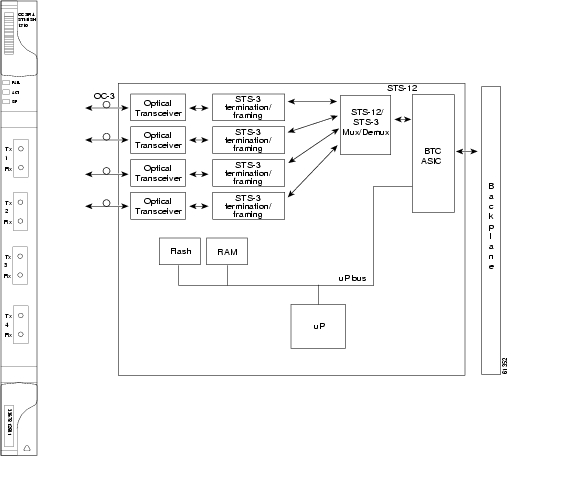
The OC3 IR 4/STM1 SH 1310 card provides four intermediate or short range SONET/SDH OC-3 ports compliant with the International Telecommunication Union's G.707, G.957, and Telcordia's GR-253. Each port operates at 155.52 Mbps over a single-mode fiber span. The card supports VT and non-concatenated or concatenated payloads at the STS-1 or STS-3c signal levels. Figure 4-1 shows the OC3 IR 4/STM1 SH 1310 faceplate and a diagram of the card.
Note
Figure 4-1 OC3 IR 4/STM1 SH 1310 faceplate and block diagram
You can install the OC3 IR 4/STM1 SH 1310 card in any multispeed or high-speed card slot. The card can be provisioned as part of a unidirectional path switched ring (UPSR) or in a linear add-drop multiplexer (ADM) configuration. Each port features a 1310 nm laser and contains a transmit and receive connector (labeled) on the card faceplate. The card uses SC connectors.
The OC3 IR 4/STM1 SH 1310 card supports 1+1 unidirectional or bidirectional protection switching. You can provision protection on a per port basis.
The OC3 IR 4/STM1 SH 1310 detects LOS, LOF, Loss of Pointer (LOP), line Alarm Indication Signal (AIS-L), and line Remote Defect Indication (RDI-L) conditions. See Alarm Troubleshooting in the Alarm Troubleshooting and Maintenance Guide for a description of these conditions. The card also counts section and line bit interleaved parity (BIP) errors.
4.2.1 OC3 IR 4/STM1 SH 1310 Card-Level Indicators
The OC3 IR 4/STM1 SH 1310 card has three card-level LED indicators.
4.2.2 OC3 IR 4/STM1 SH 1310 Port-Level Indicators
You can find the status of the four card ports using the LCD screen on the ONS 15454 fan-tray assembly. Use the LCD to view the status of any port or card slot; the screen displays the number and severity of alarms for a given port or slot.
Warning
4.2.3 OC3 IR 4/STM1 SH 1310 Card Specifications
•
–
–
–
–
–
–
–
–
–
–
–
–
•
–
–
–
–
•
–
C-Temp (15454-OC34IR1310): 0 to +55 degrees Celsius
I-Temp (15454-OC34I13-T): -40 to +65 degrees Celsius
–
–
•
–
–
–
–
•
–
–
4.3 OC12 IR/STM4 SH 1310 Card
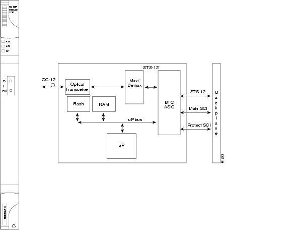
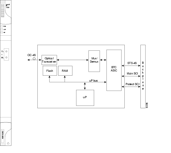
The OC12 IR/STM4 SH 1310 card provides one intermediate or short range SONET/SDH OC-12 port compliant with the International Telecommunication Union's G.707, G.957, and Telcordia's GR-253. The port operates at 622.08 Mbps over a single-mode fiber span. The card supports VT and non-concatenated or concatenated payloads at STS-1, STS-3c, STS-6c or STS-12c signal levels. Figure 4-2 shows the OC12 IR/STM4 SH 1310 faceplate and a block diagram of the card.
Note
Figure 4-2 OC12 IR/STM4 SH 1310 faceplate and block diagram
You can install the OC12 IR/STM4 SH 1310 card in any multispeed or high-speed card slot and provision the card as a drop card or span card in a two-fiber BLSR, UPSR, or in ADM (linear) configurations.
The OC12 IR/STM4 SH 1310 port features a 1310 nm laser and contains a transmit and receive connector (labeled) on the card faceplate. The OC12 IR/STM4 SH 1310 uses SC optical connections and supports 1+1 unidirectional and bidirectional protection.
The OC12 IR/STM4 SH 1310 detects LOS, LOF, LOP, AIS-L, and RDI-L conditions. See the Cisco ONS 15454 Troubleshooting Guide for a description of these conditions. The card counts section and line BIT errors.
4.3.1 OC12 IR/STM4 SH 1310 Card-Level Indicators
The OC12 IR/STM4 SH 1310 card has three card-level LED indicators.
4.3.2 OC12 IR/STM4 SH 1310 Port-Level Indicators
You can find the status of the OC-12 card port using the LCD screen on the ONS 15454 fan-tray assembly. Use the LCD to view the status of any port or card slot; the screen displays the number and severity of alarms for a given port or slot.
Warning
4.3.3 OC12 IR/STM4 SH 1310 Card Specifications
•
–
–
–
–
–
–
•
–
–
–
–
–
•
–
–
–
–
•
–
C-Temp (15454-OC121IR1310): 0 to +55 degrees Celsius
I-Temp (15454-OC121I13-T): -40 to +65 degrees Celsius
–
–
•
–
–
–
–
•
–
–
4.4 OC12 LR/STM4 LH 1310 Card
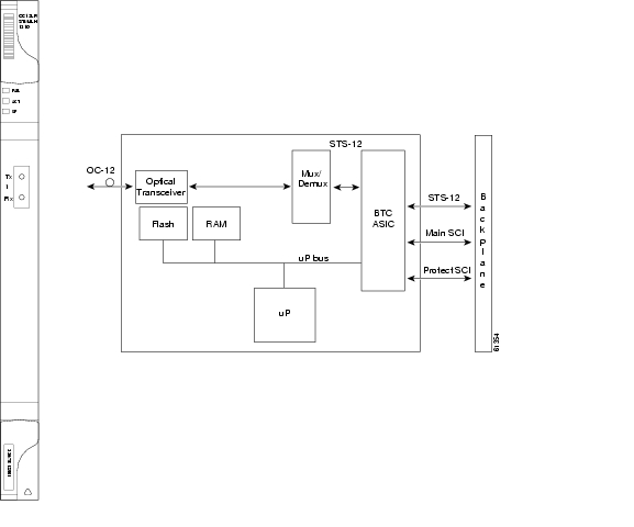
The OC12 LR/STM4 LH 1310 card provides one long-range, ITU-T G.707, ITU-T G.957, and Telcordia-compliant, GR-253 SONET OC-12 port per card. The port operates at 622.08 Mbps over a single-mode fiber span. The card supports VT and non-concatenated or concatenated payloads at STS-1, STS-3c, STS-6c or STS-12c signal levels. Figure 4-3 shows the OC12 LR/STM4 LH 1310 faceplate and a block diagram of the card.
Note
Figure 4-3 OC12 LR/STM4 LH 1310 faceplate and block diagram
You can install the OC12 LR/STM4 LH 1310 card in any multispeed or high-speed card slot and provision the card as a drop card or span card in a two-fiber BLSR (Bidirectional line switched ring), UPSR, or ADM (linear) configuration.
The OC12 LR/STM4 LH 1310 card port features a 1310 nm laser and contains a transmit and receive connector (labeled) on the card faceplate. The card uses SC optical connections supporting 1+1 unidirectional and bidirectional protection.
The OC12 LR/STM4 LH 1310 detects LOS, LOF, LOP, AIS-L, and RDI-L conditions. The card also counts section and line BIT errors.
4.4.1 OC12 LR/STM4 LH 1310 Card-Level Indicators
The OC12 LR/STM4 LH 1310 card has three card-level LED indicators.
4.4.2 OC12 LR/STM4 LH 1310 Port-Level Indicators
You can find the status of the OC12 LR/STM4 LH 1310 card port using the LCD screen on the ONS 15454 fan-tray assembly. Use the LCD to quickly view the status of any port or card slot; the screen displays the number and severity of alarms for a given port or slot.
Warning
4.4.3 OC12 LR/STM4 LH 1310 Card Specifications
•
–
–
–
–
–
–
•
–
–
–
–
–
•
–
–
–
–
•
–
C-Temp (15454-OC121LR1310): 0 to +55 degrees Celsius
I-Temp (15454-OC121L13-T): -40 to +65 degrees Celsius
–
–
•
–
–
–
–
•
–
–
4.5 OC12 LR/STM4 LH 1550 Card
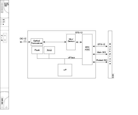
The OC12 LR/STM4 LH 1550 card provides one long-range SONET/SDH OC-12 port compliant with the International Telecommunication Union's G.707, G.957, and Telcordia's GR-253. The port operates at 622.08 Mbps over a single-mode fiber span. The card supports VT and non-concatenated, or concatenated payloads at STS-1, STS-3c, STS-6c, or STS-12c signal levels. Figure 4-4 shows the OC12 LR/STM4 LH 1550 faceplate and a block diagram of the card.
Note
Figure 4-4 OC12 LR/STM4 LH 1550 faceplate and block diagram
You can install the OC12 LR/STM4 LH 1550 card in any multispeed card slot. The OC12 LR/STM4 LH 1550 can be provisioned as part of a two-fiber BLSR, UPSR or linear ADM.
The OC12 LR/STM4 LH 1550 uses long-reach optics centered at 1550 nm and contains a transmit and receive connector (labeled) on the card faceplate. The OC12 LR/STM4 LH 1550 uses SC optical connections and supports 1+1 bidirectional or unidirectional protection switching.
The OC12 LR/STM4 LH 1550 detects LOS, LOF, LOP, AIS-L, and RDI-L conditions. The card also counts section and line BIT errors.
4.5.1 OC12 LR/STM4 LH 1550 Card-Level Indicators
The OC12 LR/STM4 LH 1550 card has three card-level LED indicators.
4.5.2 OC12 LR/STM4 LH 1550 Port-Level Indicators
You can find the status of the OC12 LR/STM4 LH 1550 card port using the LCD screen on the ONS 15454 fan-tray assembly. Use the LCD to view the status of any port or card slot; the screen displays the number and severity of alarms for a given port or slot.
Warning
4.5.3 OC12 LR/STM4 LH 1550 Card Specifications
•
–
–
–
–
–
–
•
–
–
–
–
–
•
–
–
–
–
•
–
C-Temp (15454-OC121LR1550): 0 to +55 degrees Celsius
I-Temp (15454-OC121L15-T): -40 to +65 degrees Celsius
–
–
•
–
–
–
–
•
–
–
4.6 OC12/STM4-4 Card
The OC12/STM4-4 card provides four intermediate or short range SONET/SDH OC-12/STM-4 ports compliant with the International Telecommunication Union's G.707, G.957, and Telcordia's GR-253. Each port operates at 622.08 Mbps over a single-mode fiber span. The card supports VT and non-concatenated or concatenated payloads at the STS-1, STS-3c, STS-6c, or STS-12c signal levels.
The OC12/STM4-4 card supports 1+1 unidirectional or bidirectional protection switching. You can provision protection on a per port basis.
The OC12/STM4-4 detects LOS, LOF, Loss of Pointer (LOP), line Alarm Indication Signal (AIS-L), and line Remote Defect Indication (RDI-L) conditions. The card also counts section and line bit interleaved parity (BIP) errors.
4.6.1 OC12/STM4-4 Slots and Connectors
You can install the OC12/STM4-4 card in any multispeed card slot. The card can be provisioned as part of a unidirectional path switched ring (UPSR) or in a linear add-drop multiplexer (ADM) configuration. Each port features a 1310 nm laser and contains a transmit and receive connector (labeled) on the card faceplate. The card uses SC connectors.
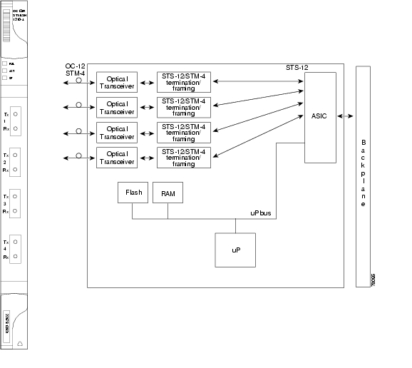
4.6.2 OC12/STM4-4 Faceplate and Block Diagram
Figure 4-1 shows the OC12/STM4-4 faceplate and a diagram of the card.
Figure 4-5 OC12/STM4-4 faceplate and block diagram
4.6.3 OC12/STM4-4 Card-Level Indicators
The OC12/STM4-4 card has three card-level LED indicators.
4.6.4 OC12/STM4-4 Port-Level Indicators
You can find the status of the four card ports using the LCD screen on the ONS 15454 fan-tray assembly. Use the LCD to view the status of any port or card slot; the screen displays the number and severity of alarms for a given port or slot.
Warning
4.6.5 OC12/STM4-4 Specifications
•
–
–
–
–
–
–
–
–
–
–
–
–
•
–
–
–
–
•
–
•
–
•
–
•
–
–
–
–
•
–
–
Note
4.7 OC48 IR 1310 Card
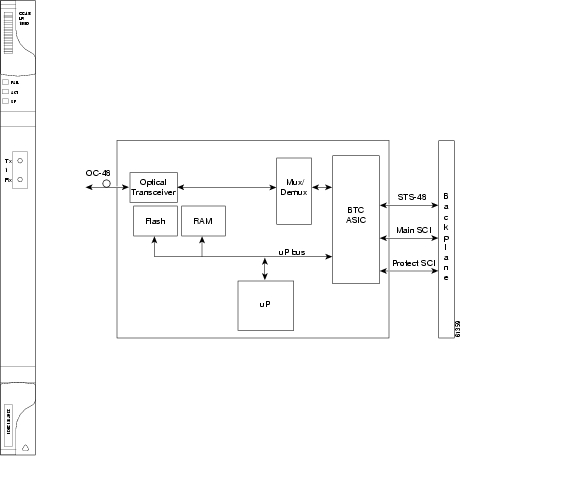
The OC48 IR 1310 card provides one intermediate-range, Telcordia-compliant, GR-253 SONET OC-48 port per card. Each port operates at 2.49 Gbps over a single-mode fiber span. The card supports VT and non-concatenated, or concatenated payloads at STS-1, STS-3c, STS-6c, STS-12c, or STS-48c signal levels. Figure 4-6 shows the OC48 IR 1310 faceplate and a block diagram of the card.
Figure 4-6 OC48 IR 1310 faceplate and block diagram
You can install the OC48 IR 1310 card in any high-speed card slot and provision the card as a drop or span card in a two-fiber or four-fiber BLSR, UPSR, or in an ADM (linear) configuration.
The OC-48 port features a 1310 nm laser and contains a transmit and receive connector (labeled) on the card faceplate. The OC48 IR 1310 uses SC connectors. The card supports 1+1 unidirectional and bidirectional protection switching.
The OC48 IR 1310 detects LOS, LOF, LOP, AIS-L, and RDI-L conditions. The card also counts section and line BIT errors.
4.7.1 OC48 IR 1310 Card-Level Indicators
The OC48 IR 1310 card has three card-level LED indicators.
4.7.2 OC48 IR 1310 Port-Level Indicators
You can find the status of the OC48 IR 1310 card port using the LCD screen on the ONS 15454 fan-tray assembly. Use the LCD to view the status of any port or card slot; the screen displays the number and severity of alarms for a given port or slot.
Warning
4.7.3 OC48 IR 1310 Card Specifications
•
–
–
–
–
–
–
•
–
–
–
–
Transmitter: Uncooled direct modulated DFB
•
–
–
–
–
•
–
C-Temp (15454-OC481IR1310): 0 to +55 degrees Celsius
–
–
•
–
–
–
–
•
–
–
4.8 OC48 LR 1550 Card
The OC48 LR 1550 card provides one long-range, Telcordia-compliant, GR-253 SONET OC-48 port per card. Each port operates at 2.49 Gbps over a single-mode fiber span. The card supports VT, non-concatenated or concatenated payloads at STS-1, STS-3c, STS-6c STS-12c or STS-48c signal levels. Figure 4-7 shows the OC48 LR 1550 faceplate and a block diagram of the card.
Figure 4-7 OC48 LR 1550 faceplate and block diagram
You can install OC48 LR 1550 cards in any high-speed slot on the ONS 15454 and provision the card as a drop or span card in a two-fiber or four-fiber BLSR, UPSR, or in an ADM (linear) configuration.
The OC48 LR 1550 port features a 1550 nm laser and contains a transmit and receive connector (labeled) on the card faceplate. The card uses SC connectors, and it supports 1+1 unidirectional and bidirectional protection switching.
The OC48 LR 1550 detects LOS, LOF, LOP, AIS-L, and RDI-L conditions. The card also counts section and line BIT errors.
4.8.1 OC48 LR 1550 Card-Level Indicators
The OC48 LR 1550 card has three card-level LED indicators.
4.8.2 OC48 LR 1550 Port-Level Indicators
You can find the status of the OC48 LR 1550 card port using the LCD screen on the ONS 15454 fan-tray assembly. Use the LCD to view the status of any port or card slot; the screen displays the number and severity of alarms for a given port or slot.
Warning
4.8.3 OC48 LR 1550 Card Specifications
•
–
–
–
–
–
–
•
–
–
–
–
–
•
–
–
–
–
•
–
C-Temp (15454-OC481LR1550): 0 to +55 degrees Celsius
–
–
•
–
–
–
–
•
–
–
4.9 OC48 IR/STM16 SH AS 1310 Card
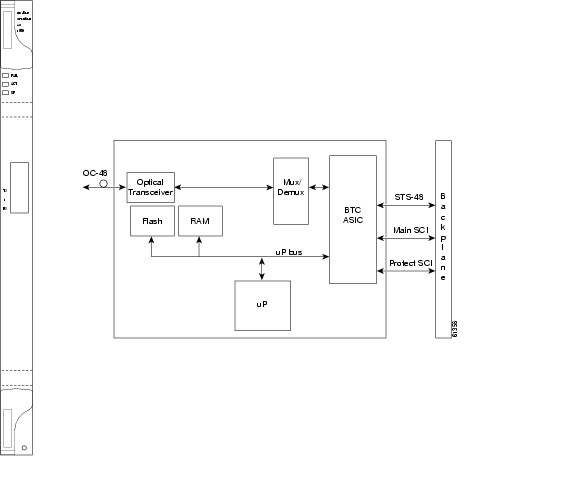
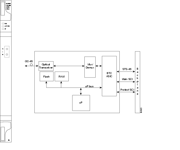
The OC48 IR/STM16 SH AS 1310 card provides one intermediate-range SONET/SDH OC-48 port compliant with the International Telecommunication Union's G.707, G.957, and Telcordia's GR-253. The port operates at 2.49 Gbps over a single-mode fiber span. The card supports VT and non-concatenated or concatenated payloads at STS-1, STS-3c, STS-6c, STS-12c, or STS-48c signal levels. Figure 4-8 shows the OC48 IR/STM16 SH AS 1310 faceplate and a block diagram of the card.
Figure 4-8 OC48 IR/STM16 SH AS 1310 faceplate and block diagram
You can install the OC48 IR/STM16 SH AS 1310 card in any multispeed or high-speed card slot on the ONS 15454 and provision the card as a drop or span card in a two-fiber or four-fiber BLSR, UPSR, or in an ADM (linear) configuration.
The OC-48 port features a 1310 nm laser and contains a transmit and receive connector (labeled) on the card faceplate. The OC48 IR/STM16 SH AS 1310 uses SC connectors. The card supports 1+1 unidirectional and bidirectional protection switching.
The OC48 IR/STM16 SH AS 1310 detects LOS, LOF, LOP, AIS-L, and RDI-L conditions. The card also counts section and line BIT errors.
4.9.1 OC48 IR/STM16 SH AS 1310 Card-Level Indicators
The OC48 IR/STM16 SH AS 1310 card has three card-level LED indicators.
4.9.2 OC48 IR/STM16 SH AS 1310 Port-Level Indicators
You can find the status of the OC48 IR/STM16 SH AS 1310 card port using the LCD screen on the ONS 15454 fan-tray assembly. Use the LCD to view the status of any port or card slot; the screen displays the number and severity of alarms for a given port or slot.
Warning
4.9.3 OC48 IR/STM16 SH AS 1310 Compatibility
Use the XC10G card, the TCC+ card, the new 15454-SA-ANSI shelf assembly, and Software R3.1 or higher to enable the OC48 IR/STM16 SH AS 1310 card. The OC48 IR/STM16 SH AS 1310 card uses the BTC backplane interface to provide recognition in both the high-speed and multispeed slots.
4.9.4 OC48 IR/STM16 SH AS 1310 Card Specifications
•
–
–
–
–
–
–
•
–
–
–
–
–
•
–
–
–
–
•
–
C-Temp (15454-OC481IR1310A): 0 to +55 degrees Celsius
–
–
•
–
–
–
–
•
–
–
4.10 OC48 LR/STM16 LH AS 1550 Card
The OC48 LR/STM16 LH AS 1550 card provides one long-range SONET/SDH OC-48 port compliant with the International Telecommunication Union's G.707, G.957, and Telcordia's GR-253. Each port operates at 2.49 Gbps over a single-mode fiber span. The card supports VT and non-concatenated or concatenated payloads at STS-1, STS-3c, STS-6c, STS-12c, or STS-48c signal levels. Figure 4-9 shows the OC48 LR/STM16 LH AS 1550 faceplate and a block diagram of the card.
Figure 4-9 OC48 LR/STM16 LH AS 1550 faceplate and block diagram
You can install OC48 LR/STM16 LH AS 1550 cards in any multispeed or high-speed slot on the ONS 15454 and provision the card as a drop or span card in a two-fiber or four-fiber BLSR, UPSR, or in an ADM (linear) configuration.
The OC48 LR/STM16 LH AS 1550 port features a 1550 nm laser and contains a transmit and receive connector (labeled) on the card faceplate. The card uses SC connectors, and it supports 1+1 unidirectional and bidirectional protection switching.
The OC48 LR/STM16 LH AS 1550 detects LOS, LOF, LOP, AIS-L, and RDI-L conditions. The card also counts section and line BIT errors.
4.10.1 OC48 LR/STM16 LH AS 1550 Card-Level Indicators
The OC48 LR/STM16 LH AS 1550 card has three card-level LED indicators.
4.10.2 OC48 LR/STM16 LH AS 1550 Port-Level Indicators
You can find the status of the OC48 LR/STM16 LH AS 1550 card port using the LCD screen on the ONS 15454 fan-tray assembly. Use the LCD to view the status of any port or card slot; the screen displays the number and severity of alarms for a given port or slot.
Warning
4.10.3 OC48 LR/STM16 LH AS 1550 Compatibility
Use the XC10G card, the TCC+ card, the new 15454-SA-ANSI shelf assembly, and Software R3.1 or higher to enable the OC48 LR/STM16 LH AS 1550 card. The OC48 LR/STM16 LH AS 1550 card uses the BTC backplane interface to provide recognition in both the high-speed and multispeed slots.
4.10.4 OC48 LR/STM16 LH AS 1550 Card Specifications
•
–
–
–
–
–
–
•
–
–
–
–
–
•
–
–
–
–
•
–
C-Temp (15454-OC481LR1550A): 0 to +55 degrees Celsius
–
–
•
–
–
–
–
•
–
–
4.11 OC48 ELR/STM16 EH 100 GHz Cards
Thirty-seven distinct OC48 ITU 100GHz dense wavelength division multiplexing (DWDM) cards provide the ONS 15454 DWDM channel plan. Each OC-48 DWDM card has one SONET OC-48/SDH STM-16 port that complies with Telcordia, GR-253 SONET, and the International Telecommunication Union's ITU-T G.692, and ITU-T G.958.
The port operates at 2.49 Gbps over a single-mode fiber span. The card carries VT, concatenated, and non-concatenated payloads at STS-1, STS-3c, STS-6c, STS-12c, or STS-48c signal levels. Figure 4-10 shows the OC48 ELR/STM16 EH 100 GHz faceplate and a block diagram of the card.
Figure 4-10 OC48 ELR/STM16 EH 100 GHz faceplate and block diagram
Nineteen of the cards operate in the blue band with spacing of 100 GHz on the ITU grid standard G.692 and Telcordia GR-2918-CORE, issue 2 (1528.77 nm, 1530.33 nm, 1531.12 nm, 1531.90 nm, 1532.68 nm, 1533.47 nm, 1534.25 nm, 1535.04 nm, 1535.82 nm, 1536.61 nm, 1538.19 nm, 1538.98 nm, 1539.77 nm, 1540.56 nm, 1541.35 nm, 1542.14 nm, 1542.94 nm, 1543.73 nm, 1544.53 nm).
The other eighteen cards operate in the red band with spacing of 100 GHz on the ITU grid (1546.12 nm, 1546.92 nm, 1547.72 nm, 1548.51 nm,1549.32 nm, 1550.12 nm, 1550.92 nm, 1551.72 nm, 1552.52 nm, 1554.13 nm, 1554.94 nm, 1555.75 nm, 1556.55 nm, 1557.36 nm, 1558.17 nm, 1558.98 nm, 1559.79 nm, 1560.61 nm). These cards are also designed to interoperate with the Cisco ONS 15216 DWDM solution.
You can install the OC48 ELR/STM16 EH 100 GHz cards in any high-speed slot and provision the card as a drop or span card in a two-fiber or four-fiber BLSR, UPSR, or in an ADM (linear) configuration. Each OC48 ELR/STM16 EH 100 GHz card uses extended long reach optics operating individually within the ITU-T 100 GHz grid. The OC-48 DWDM cards are intended to be used in applications with long unregenerated spans of up to 200 km (with mid-span amplification). These transmission distances are achieved through the use of inexpensive optical amplifiers (flat gain amplifiers) such as Cisco ONS 15216 erbium-doped fiber amplifiers (EDFAs).
Maximum system reach in filterless applications is 26 dB without the use of optical amplifiers or regenerators. However, system reach also depends on the condition of the facilities, number of splices and connectors, and other performance-affecting factors. When used in combination with ONS 15216 100 GHz filters, the link budget is reduced by the insertion loss of the filters plus an additional 2dB power penalty. The OC-48 ELR DWDM cards wavelength stability is +/- 0.12 nm for the life of the product and over the full range of operating temperatures. Each interface contains a transmitter and receiver.
The OC-48 ELR cards detect loss of signal (LOS), loss of frame (LOF), loss of pointer (LOP), and line-layer alarm indication signal (AIS-L) conditions. The cards also count section and line BIT errors.
4.11.1 OC48 ELR 100 GHz Card-Level Indicators
The OC48 ELR/STM16 EH 100 GHz cards have three card-level LED indicators.
4.11.2 OC48 ELR 100 GHz Port-Level Indicators
You can find the status of the OC48 ELR card ports using the LCD screen on the ONS 15454 fan-tray assembly. Use the LCD to quickly view the status of any port or card slot; the screen displays the number and severity of alarms for a given port or slot.
Warning
4.11.3 OC48 ELR 100 GHz Compatibility
The OC48 ELR/STM16 EH 100 GHz card requires a cross-connect (XC) card, cross-connect virtual tributary (XCVT) card, or an XC10G for proper operation.
4.11.4 OC48 ELR 100 GHz Card Specifications
•
–
–
–
–
–
–
•
–
–
–
–
•
–
–
–
–
–
•
–
C-Temp: 0 to +55 degrees Celsius (For product names, see Card Temperature Ranges)
–
–
•
–
–
–
–
•
–
–
4.12 OC48 ELR 200 GHz Cards
Eighteen distinct OC48 ITU 200GHz dense wavelength division multiplexing (DWDM) cards provide the ONS 15454 DWDM channel plan. Each OC-48 DWDM card provides one Telcordia-compliant, GR-253 SONET OC-48 port. The port operates at 2.49 Gbps over a single-mode fiber span. The card carries VT, concatenated, and non-concatenated payloads at STS-1, STS-3c, STS-6c, STS-12c, or STS-48c signal levels. Figure 4-10 shows the OC48 ELR DWDM faceplate and a block diagram of the card.
Figure 4-11 OC48 ELR 200 GHz faceplate and block diagram
Nine of the cards operate in the blue band with spacing of 200 GHz on the ITU grid (1530.33 nm, 1531.90 nm, 1533.47 nm, 1535.04 nm, 1536.61 nm, 1538.19 nm, 1539.77 nm, 1541.35 nm, 1542.94 nm).
The other nine cards operate in the red band with spacing of 200 GHz on the ITU grid
(1547.72 nm, 1549.32 nm, 1550.92 nm, 1552.52 nm, 1554.13 nm, 1555.75 nm, 1557.36 nm, 1558.98 nm, 1560.61 nm). These cards are also designed to interoperate with the Cisco ONS 15216 DWDM solution.You can install the OC48 ELR 200 GHz cards in any high-speed slot and provision the card as a drop or span card in a two-fiber or four-fiber BLSR, UPSR, or in an ADM (linear) configuration. Each OC48 ELR DWDM card uses extended long reach optics operating individually within the ITU-T 200 GHz grid. The OC48 DWDM cards are intended to be used in applications with long unregenerated spans of up to 200 km (with mid-span amplification). These transmission distances are achieved through the use of inexpensive optical amplifiers (flat gain amplifiers) such as erbium doped fiber amplifiers (EDFAs). Using co-located amplification, distances up to 200 km can be achieved for a single channel (160 km for 8 channels).
Maximum system reach in filterless applications is 24 dB or approximately 80 km without the use of optical amplifiers or regenerators. However, system reach also depends on the condition of the facilities, number of splices and connectors or other performance-affecting factors. The OC48 ELR DWDM cards feature wavelength stability of +/- 0.25 nm. Each interface contains a transmitter and receiver.
The OC48 ELR DWDM cards are the first in a family of cards meant to support extended long reach applications in conjunction with optical amplification. Using electro-absorption technology, the OC48 DWDM cards provide a solution at the lower-extended long reach distances.
The OC48 LR 1550 interface features a 1550 nm laser and contains a transmit and receive connector (labeled) on the card faceplate. The card uses SC connectors and supports 1+1 unidirectional and bidirectional protection switching.
The OC48 ELR cards detect LOS, LOF, LOP, AIS-L, and RDI-L conditions. The cards also count section and line BIT errors.
To enable APS, the OC48 ELR cards extract the K1 and K2 bytes from the SONET overhead. The DCC bytes are forwarded to the TCC+ card; the TCC+ terminates the DCC.
4.12.1 OC48 ELR 200 GHz Card-Level Indicators
The OC48 ELR cards have three card-level LED indicators.
4.12.2 OC48 ELR 200 GHz Port-Level Indicators
You can find the status of the OC48 ELR card ports using the LCD screen on the ONS 15454 fan-tray assembly. Use the LCD to quickly view the status of any port or card slot; the screen displays the number and severity of alarms for a given port or slot.
Warning
4.12.3 OC48 ELR 200 GHz Compatibility
The OC48 ELR/STM16 EH 200 GHz card requires an XC card, XCVT card, or XC10G card for proper operation.
4.12.4 OC48 ELR 200 GHz Card Specifications
•
–
–
–
–
–
–
•
–
–
–
–
•
–
–
–
–
•
–
C-Temp: 0 to +55 degrees Celsius
–
–
•
–
–
–
–
•
–
–
4.13 OC192 LR/STM64 LH 1550 Card
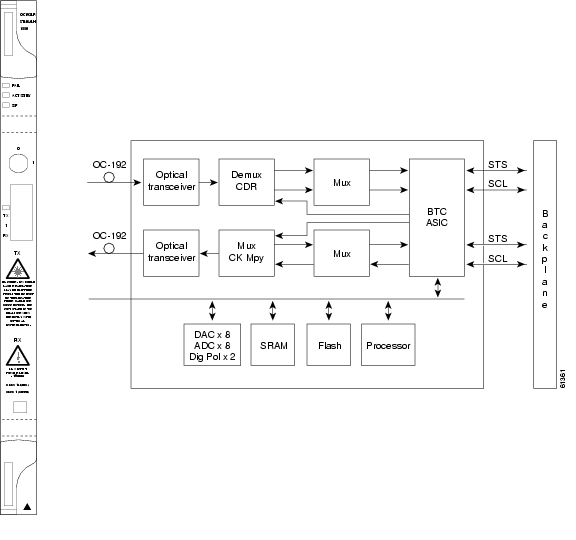
The OC192 LR/STM64 LH 1550 card provides one long-range SONET/SDH OC-192 port compliant with the International Telecommunication Union's G.707, G.957, and Telcordia's GR-1377 and GR-253. The card port operates at 9.96 Gbps over unamplified distances up to 80 km with different types of fiber such as C-SMF or dispersion compensated fiber limited by loss and/or dispersion. The card supports VT and non-concatenated or concatenated payloads.
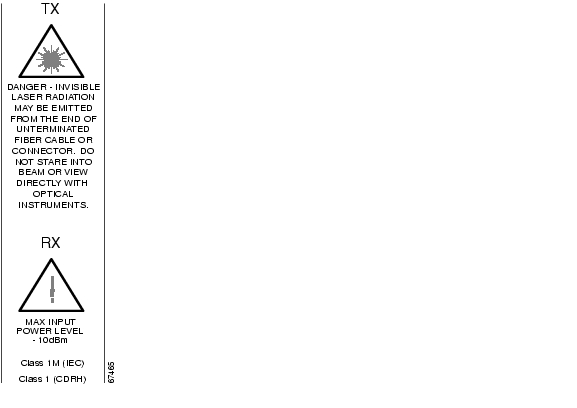
Figure 4-12 shows the OC192 LR/STM64 LH 1550 faceplate and a block diagram of the card. Figure 4-13 shows an enlarged view of the faceplate warning.
Figure 4-12 OC192 LR/STM64 LH 1550 faceplate and block diagram
Figure 4-13 Enlarged section of the OC192 LR/STM64 LH 1550 faceplate
Caution
You can install OC192 LR/STM64 LH 1550 cards in any high-speed slot on the ONS 15454 and provision the card as a drop or span card in a two-fiber or four-fiber BLSR, UPSR, or in an ADM (linear) configuration.
The OC-192 card port features a 1550 nm laser and contains a transmit and receive connector (labeled) on the card faceplate.
Warning
The card uses a dual SC connector for optical cable termination. The card supports 1+1 unidirectional and bidirectional facility protection. It also supports 1:1 protection in four-fiber bidirectional line switched ring applications where both span switching and ring switching may occur.
The OC192 LR/STM64 LH 1550 card detects SF, LOS, or LOF conditions on the optical facility. The card also counts section and line BIT errors from B1 and B2 byte registers in the section and line overhead.
4.13.1 OC192 LR/STM64 LH 1550 Card-Level Indicators
The OC192 LR/STM64 LH 1550 card has three card-level LED indicators.
4.13.2 OC192 LR/STM64 LH 1550 Port-Level Indicators
You can find the status of the OC192 LR/STM64 LH 1550 card port using the LCD screen on the ONS 15454 fan-tray assembly. Use the LCD to view the status of the port or card slot; the screen displays the number and severity of alarms for a given port or slot.
Warning
4.13.3 OC192 LR/STM64 LH 1550 Compatibility
Use the XC10G card, the TCC+ card, the new 15454-SA-ANSI shelf assembly, and Software R3.1 or higher to enable the OC192 LR/STM64 LH 1550 card.
4.13.4 OC192 LR/STM64 LH 1550 Card Specifications
•
–
–
–
•
Note
–
–
•
–
–
–
–
–
•
–
–
–
–
•
–
C-Temp (15454-OC192LR1550): 0 to +55 degrees Celsius
–
–
•
–
–
–
–
•
–
–
![]()
![]()
![]()
![]()
![]()
![]()
![]()
![]()
Posted: Mon Feb 25 15:36:51 PST 2008
All contents are Copyright © 1992--2008 Cisco Systems, Inc. All rights reserved.
Important Notices and Privacy Statement.