|
|

Table Of Contents
3.2.1 EC1-12 Slots and Connectors
3.2.2 EC1-12 Faceplate and Block Diagram
3.2.4 EC1-12 Card-Level Indicators
3.2.5 EC1-12 Port-Level Indicators
3.3.1 DS1N-14 Features and Functions
3.3.2 DS1-14 and DS1N-14 Slots and Connectors
3.3.3 DS1-14 and DS1N-14 Faceplate and Block Diagram
3.3.4 DS1-14 and DS1N-14 Hosted by the Cross-Connect
3.3.5 DS1-14 and DS1N-14 Card-Level Indicators
3.3.6 DS1-14 and DS1N-14 Port-Level Indicators
3.3.7 DS1-14 and DS1N-14 Specifications
3.4.1 DS3N-12 Features and Functions
3.4.2 DS3-12 and DS3N-12 Slots and Connectors
3.4.3 DS3-12 and DS3N-12 Faceplate and Block Diagram
3.4.4 DS3-12 and DS3N-12 Card-Level Indicators
3.4.5 DS3-12 and DS3N-12 Port-Level Indicators
3.4.6 DS3-12 and DS3N-12 Specifications
3.5 DS3-12E and DS3N-12E Cards
3.5.1 DS3N-12E Features and Functions
3.5.2 DS3-12E and DS3N-12E Slots and Connectors
3.5.3 Faceplate and Block Diagram
3.5.4 DS3-12E and DS3N-12E Card-Level Indicators
3.5.5 DS3-12E and DS3N-12E Port-Level Indicators
3.5.6 DS3-12E and DS3N-12E Specifications
3.6.1 DS3XM-6 Slots and Connectors
3.6.2 DS3XM-6 Faceplate and Block Diagram
3.6.4 DS3XM-6 Card-Level Indicators
3.6.5 DS3XM-6 Port-Level Indicators
3.7 Electrical Card Comparisons
3.8 Electrical Interface Assemblies
3.10.1 Twisted Pair Wire-Wrap Cables
3.10.2 Electrical Interface Adapters
3.11 Cable Routing and Management
3.11.1 Coaxial Cable Management
3.11.2 DS-1 Twisted-Pair Cable Management
3.11.3 AMP Champ Cable Management
Electrical Cards and Cable
This chapter describes Cisco ONS 15454 electrical card features and functions. For installation and card turn-up procedures, refer to the Cisco ONS 15454 Procedure Guide.
Chapter topics include:
•
Electrical Interface Assemblies
•
3.1 Electrical Card Warnings
Warning
Caution
Note
3.2 EC1-12 Card
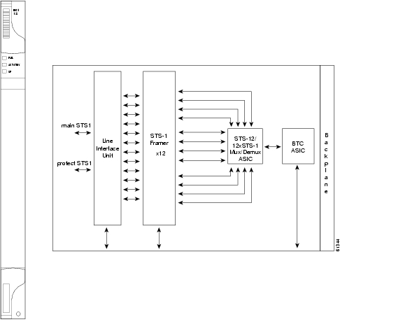
The EC1-12 card provides 12 Telcordia-compliant, GR-253 STS-1 electrical ports per card. Each port operates at 51.840 Mbps over a single 75 ohm 728A or equivalent coaxial span.
STS path selection for UNEQ-P, AIS-P, and bit error rate (BER) thresholds is done on the SONET ring interfaces (optical cards) in conjunction with the STS cross-connect. The EC1-12 terminates but does not select the 12 working STS-1 signals from the backplane. The EC1-12 maps each of the 12 received EC1 signals into 12 STS-1s with visibility into the SONET path overhead.
An EC1-12 card can be 1:1 protected with another EC1-12 card but cannot protect more than one EC1-12 card. You must install the EC1-12 in an even-numbered slot to serve as a working card and in an odd-numbered slot to serve as a protect card.
3.2.1 EC1-12 Slots and Connectors
You can install the EC1-12 card in any multispeed or high-speed card slot on the ONS 15454. Each EC1-12 interface features DSX-level (digital signal cross-connect frame) outputs supporting distances up to 450 feet depending on facility conditions.
3.2.2 EC1-12 Faceplate and Block Diagram
Figure 3-1 shows the EC1-12 faceplate and a block diagram of the card.
Figure 3-1 EC1-12 faceplate and block diagram
3.2.3 EC1-12 Hosted by XCVT
All 14 VT1.5 payloads from a EC1-12 card are carried in a single STS-1 to the XC or XCVT card where the payload is further aggregated for efficient STS-1 transport. XCVT cards host a maximum of 336 bidirectional VT1.5s.
3.2.4 EC1-12 Card-Level Indicators
The EC1-12 card faceplate has three card-level LEDs.
3.2.5 EC1-12 Port-Level Indicators
You can obtain the status of the EC1-12 card ports using the LCD screen on the ONS 15454 fan-tray. Use the LCD to view the status of any port or card slot; the screen displays the number and severity of alarms for a given port or slot. See Alarm Troubleshooting for a complete description of the alarm messages.
3.2.6 EC1-12 Specifications
The EC1-12 card specifications are shown in Table 3-2.
3.3 DS1-14 and DS1N-14 Cards
The ONS 15454 DS1-14 card provides 14 Telcordia-compliant, GR-499 DS-1 ports. Each port operates at 1.544 Mbps over a 100 ohm twisted-pair copper cable. The DS1-14 card can function as a working or protect card in 1:1 protection schemes and as a working card in 1:N protection schemes.
The DS1-14 card supports 1:1 protection. The DS1-14 can be a working card in a 1:N protection scheme with the proper backplane EIA and wire-wrap or AMP Champ connectors. You can also provision the DS1-14 to monitor for line and frame errors in both directions.
You can group and map DS1-14 card traffic in STS-1 increments to any other card in an ONS 15454 except DS-3 cards. Each DS-1 is asynchronously mapped into a SONET VT1.5 payload and the card carries a DS-1 payload intact in a VT1.5. For performance monitoring purposes, you can gather bidirectional DS-1 frame-level information (loss of frame, parity errors, cyclic redundancy check [CRC] errors, etc.).
3.3.1 DS1N-14 Features and Functions
The DS1N-14 card supports the same features as the DS1-14 card in addition to enhanced protection schemes. The DS1N-14 is capable of 1:N (N<5) protection with the proper backplane EIA and wire-wrap or AMP Champ connectors. The DS1N-14 card can function as a working or protect card in 1:1 or 1:N protection schemes.
3.3.2 DS1-14 and DS1N-14 Slots and Connectors
•
You can install the DS1-14 card in any multispeed or high-speed card slot on the ONS 15454. Each DS1-14 port has DSX-level (digital signal cross-connect frame) outputs supporting distances up to 655 feet.
•
If you use the DS1N-14 as a standard DS-1 card in a 1:1 protection group, you can install the DS1N-14 card in any multispeed or high-speed card slot on the ONS 15454. If you use the card's 1:N functionality, you must install a DS1N-14 card in Slots 3 and 15. Each DS1N-14 port features DSX-level outputs supporting distances up to 655 feet depending on facility conditions.
3.3.3 DS1-14 and DS1N-14 Faceplate and Block Diagram
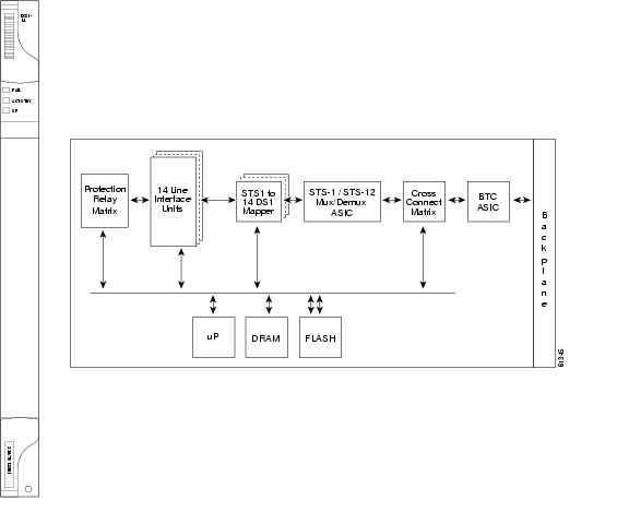
Figure 3-2 shows the DS1-14 and DS1N-14 faceplates and block diagrams of the cards.
Figure 3-2 DS1-14 faceplate and block diagram
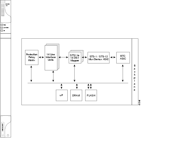
Figure 3-3 shows the DS1N-14 faceplate and a block diagram of the card.
Figure 3-3 DS1N-14 faceplate and block diagram
3.3.4 DS1-14 and DS1N-14 Hosted by the Cross-Connect
All 14 VT1.5 payloads from a DS1-14 card are carried in a single STS-1 to the XCVT or XC10G card where the payload is further aggregated for efficient STS-1 transport. The XC10G and XCVT cards manage up to 336 bidirectional VT1.5 ports.
3.3.5 DS1-14 and DS1N-14 Card-Level Indicators
The DS1-14 and DS1N-14 card faceplate has three LEDs shown in Table 3-3.
3.3.6 DS1-14 and DS1N-14 Port-Level Indicators
You can obtain the status of the DS1-14 and DS1N-14 card ports using the LCD screen on the ONS 15454 fan-tray assembly. Use the LCD to view the status of any port or card slot; the screen displays the number and severity of alarms for a given port or slot. See Alarm Troubleshooting for a complete description of the alarm messages.
3.3.7 DS1-14 and DS1N-14 Specifications
The DS1-14 and DS1N-14 card specifications are shown in Table 3-4.
3.4 DS3-12 and DS3N-12 Cards
The ONS 15454 DS3-12 card provides 12 Telcordia-compliant, GR-499 DS-3 ports per card. Each port operates at 44.736 Mbps over a single 75 ohm 728A or equivalent coaxial span. The DS3-12 card operates as a working or protect card in 1:1 protection schemes and as a working card in 1:N protection schemes.
The DS3-12 card supports 1:1 protection with the proper backplane EIA. EIAs are available with BNC or SMB connectors.
Caution
3.4.1 DS3N-12 Features and Functions
Other than the protection capabilities, the DS3-12 and DS3N-12 cards are identical. The DS3N-12 can operate as the protect card in a 1:N (N<5) DS-3 protection group. It has additional circuitry not present on the basic DS3-12 card that allows it to protect up to five working DS3-12 cards. The basic DS3-12 card can only function as the protect card for one other DS3-12 card.
3.4.2 DS3-12 and DS3N-12 Slots and Connectors
You can install the DS3-12 or DS3N-12 card in any multispeed or high-speed card slot on the ONS 15454. Each DS3-12 or DS3N-12 card port features DSX-level outputs supporting distances up to 450 feet depending on facility conditions. With the proper backplane EIA, the card supports BNC or SMB connectors.
3.4.3 DS3-12 and DS3N-12 Faceplate and Block Diagram
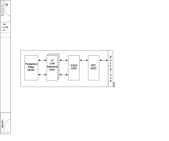
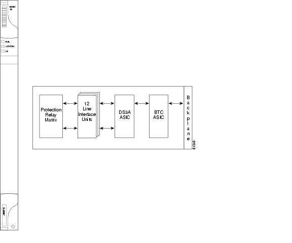
Figure 3-4 shows the DS3-12 faceplates, and a block diagram of the card.
Figure 3-4 DS3-12 faceplate and block diagram
Figure 3-5 shows the DS3N-12 faceplate and a diagram of the card.
Figure 3-5 DS3N-12 faceplate and block diagram
3.4.4 DS3-12 and DS3N-12 Card-Level Indicators
The DS3-12 and DS3N-12 card faceplates have three LEDs shown in Table 3-5.
3.4.5 DS3-12 and DS3N-12 Port-Level Indicators
You can find the status of the 12 DS3-12 and 12 DS3N-12 card ports using the LCD screen on the ONS 15454 fan-tray assembly. Use the LCD to view the status of any port or card slot; the screen displays the number and severity of alarms for a given port or slot. See Alarm Troubleshooting for a complete description of the alarm messages.
3.4.6 DS3-12 and DS3N-12 Specifications
The DS3-12 and DS3N-12 card specifications are shown in Table 3-6.
3.5 DS3-12E and DS3N-12E Cards
The ONS 15454 DS3-12E card provides 12 Telcordia-compliant ports per card. Each port operates at 44.736 Mbps over a single 75 ohm 728A or equivalent coaxial span. The DS3-12E card provides enhanced performance monitoring functions. The DS3-12E can detect several different errored logic bits within a DS-3 frame. This function allows the ONS 15454 to identify a degrading DS-3 facility caused by upstream electronics (DS-3 Framer). In addition, DS3 frame format auto detection and J1 path trace are supported. By monitoring additional overhead in the DS-3 frame, subtle network degradations can be detected.
The following list summarizes DS3-12E card features:
•
•
•
•
•
•
•
•
•
•
The DS3-12E supports a 1:1 protection scheme, meaning it can operate as the protect card for one other DS3-12E card.
3.5.1 DS3N-12E Features and Functions
The DS3N-12E can operate as the protect card in a 1:N (N<5) DS-3 protection group. It has additional circuitry not present on the basic DS3-12E card that allows it to protect up to five working DS3-12E cards. The basic DS3-12E card can only function as the protect card for one other DS3-12E card.
3.5.2 DS3-12E and DS3N-12E Slots and Connectors
You can install the DS3-12E and DS3N-12E cards in any multispeed or high-speed card slot on the ONS 15454. Each DS3-12E and DS3N-12E port features DSX-level outputs supporting distances up to 450 feet. With the proper backplane EIA, the card supports BNC or SMB connectors.
3.5.3 Faceplate and Block Diagram
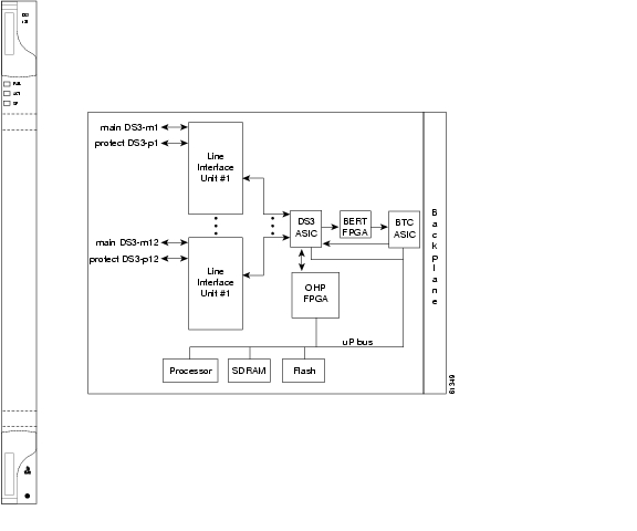
Figure 3-6 DS3-12E faceplate and block diagram
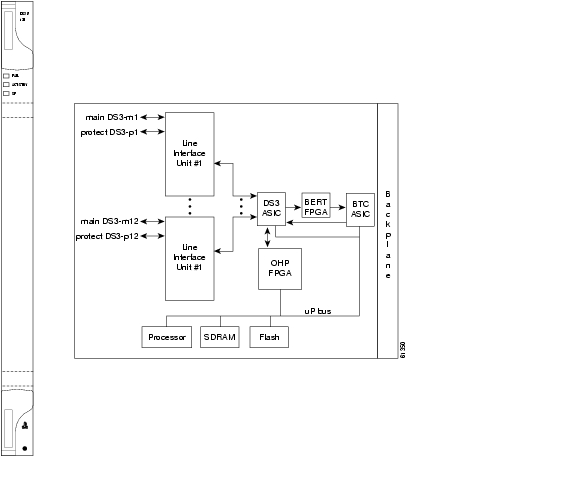
Figure 3-7 shows the DS3N-12E faceplate and a diagram of the card.
Figure 3-7 DS3N-12E faceplate and block diagram
3.5.4 DS3-12E and DS3N-12E Card-Level Indicators
The DS3-12E and DS3-12E card faceplate has three LEDs shown in Table 3-7.
3.5.5 DS3-12E and DS3N-12E Port-Level Indicators
You can find the status of the DS3-12E and DS3N-12E card ports using the LCD screen on the ONS 15454 fan-tray assembly. Use the LCD to quickly view the status of any port or card slot; the screen displays the number and severity of alarms for a given port or slot. See Alarm Troubleshooting for a complete description of the alarm messages.
3.5.6 DS3-12E and DS3N-12E Specifications
The DS3-12E and DS3N-12E card specifications are shown in Table 3-8.
3.6 DS3XM-6 Card
The DS3XM-6 card, commonly referred to as a transmux card, provides six Telcordia-compliant, GR-499-CORE M13 multiplexing functions. The DS3XM-6 converts six framed DS-3 network connections to 28x6 or 168 VT1.5s. You cannot create circuits from a DS3XM-6 card to a DS-3 card. DS3XM-6 cards operate at the VT1.5 level.
3.6.1 DS3XM-6 Slots and Connectors
The DS3XM-6 card supports 1:1 protection with the proper backplane EIA. EIAs are available with BNC or SMB connectors.
You can install the DS3XM-6 in any multispeed or high-speed card slot. Each DS3XM-6 port features DSX-level outputs supporting distances up to 450 feet depending on facility conditions.
3.6.2 DS3XM-6 Faceplate and Block Diagram
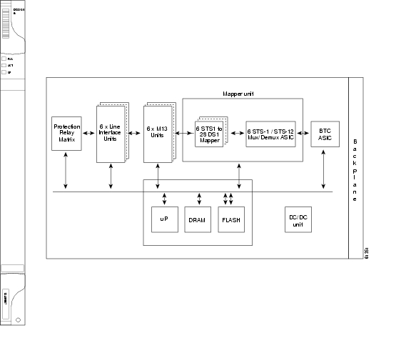
Figure 3-8 shows the DS3XM-6 faceplate and a block diagram of the card.
Figure 3-8 DS3XM-6 faceplate and block diagram
3.6.3 DS3XM-6 Hosted By XCVT
The DS3XM-6 card works in conjunction with the XCVT card. A single DS3XM-6 can demultiplex (map down to a lower rate) six DS-3 signals into 168 VT1.5s that the XCVT card then manages and cross connects. XCVT cards host a maximum of 336 bidirectional VT1.5s or two DS3XM-6 cards. In most network configurations two DS3XM-6 cards are paired together as working and protect cards.
3.6.4 DS3XM-6 Card-Level Indicators
The DS3XM-6 card faceplate has three LEDs.
3.6.5 DS3XM-6 Port-Level Indicators
You can find the status of the six DS3XM-6 card ports using the LCD screen on the ONS 15454 fan-tray assembly. Use the LCD to quickly view the status of any port or card slot; the screen displays the number and severity of alarms for a given port or slot. See Alarm Troubleshooting for a complete description of the alarm messages.
3.6.6 DS3XM-6 Specifications
The DS3XC-6 card specifications are shown in Table 3-10.
3.7 Electrical Card Comparisons
3.8 Electrical Interface Assemblies
Optional EIA backplane covers are typically pre-installed when ordered with the ONS 15454. EIAs must be ordered when using DS-1, DS-3, DS3XM-6, or EC-1 cards. A minimum amount of assembly may be required when EIAs are ordered separately from the ONS 15454. Four different EIA backplane covers are available for the ONS 15454: BNC, High-Density BNC, SMB, and AMP Champ. This section describes each EIA in detail. If the shelf was not shipped with the correct EIA interface, you must order and install the correct EIA.
EIAs are attached to the shelf assembly backplane to provide electrical interface cable connections. EIAs are available with SMB and BNC connectors for DS-3 or EC-1 cards. EIAs are available with AMP Champ connectors for DS-1 cards. You must use SMB EIAs for DS-1 twisted-pair cable installation. You can install EIAs on one or both sides of the ONS 15454 backplane in any combination (in other words, AMP Champ on Side A and BNC on Side B or High-Density BNC on side A and SMB on side B, and so forth).
EIAs have two sides. As you face the rear of the ONS 15454 shelf assembly, the right-hand side is the A side and the left-hand side is the B side. You can install EIAs on one or both sides of the ONS 15454 backplane in any combination. For example, you can use an AMP Champ EIA on side A and a BNC EIA on side B. The top of the EIA connector columns are labelled with the corresponding slot number, and EIA connector pairs are marked Tx and Rx to correspond to transmit and receive cables. EIAs come pre-installed on the ONS 15454 when ordered with the node.
If you are installing EIAs after the shelf assembly is installed, plug the EIA into the backplane. The EIA has six electrical connectors that plug into six corresponding backplane connectors. The EIA backplane must replace the standard sheet metal cover to provide access to the coaxial cable connectors. The EIA sheet metal covers use the same screw holes as the solid backplane panels, but they have 12 additional 6-32 x 1/2 inch phillips screw holes so you can screw down the cover and the board using standoffs on the EIA board. This section describes each EIA.
Table 3-13 gives the product numbers and common names for EIAs.
3.8.1 BNC EIA
The ONS 15454 BNC EIA supports 24 DS-3 circuits on each side of the ONS 15454 (24 transmit and 24 receive connectors). If you install BNC EIAs on both sides of the shelf assembly, the ONS 15454 hosts up to 48 circuits. The BNC connectors on the EIA supports Trompeter UCBJ224 (75 Ohm) 4 leg connectors (King or ITT are also compatible). Right-angle mating connectors for the connecting cable are AMP 413588-2 (75 Ohm) connectors. If preferred, you can also use a straight connector of the same type. Use RG-59/U cable to connect to the ONS 15454 BNC EIA. These cables are recommended to connect to a patch panel and are designed for long runs of up to 450 feet. You can use BNC EIAs for DS-3 (including the DS3XM-6) or EC-1 cards.
Figure 3-9 shows the ONS 15454 with pre-installed BNC EIAs.
To install coaxial cable with BNC connectors, refer to the Cisco ONS 15454 Procedure Guide.
Figure 3-9 A BNC backplane for use in 1:1 protection schemes
3.8.1.1 BNC Connectors
The EIA side marked "A" has 24 pairs of BNC connectors. The first 12 pairs of BNC connectors correspond to Ports 1-12 for a 12-port card and map to Slot 2 on the shelf assembly. The BNC connector pairs are marked "Tx" and "Rx" to indicate transmit and receive cables for each port. You can install an additional card in Slot 1 as a protect card for the card in Slot 2. The second 12 BNC connector pairs correspond to Ports 1-12 for a 12-port card and map to Slot 4 on the shelf assembly. You can install an additional card in Slot 3 as a protect card for the card in Slot 4. Slots 5 and 6 do not support DS-3 cards when BNC connectors are used.
The EIA side marked "B" provides an additional 24 pairs of BNC connectors. The first 12 BNC connector pairs correspond to Ports 1-12 for a 12-port card and map to Slot 14 on the shelf assembly. The BNC connector pairs are marked "Tx" and "Rx" to indicate transmit and receive cables for each port. You can install an additional card in Slot 15 as a protect card for the card in Slot 14. The second 12 BNC connector pairs correspond to Ports 1-12 for a 12-port card and map to Slot 16 on the shelf assembly. You can install an additional card in Slot 17 as a protect card for the card in Slot 16. Slots 12 and 13 do not support DS-3 cards when BNC connectors are used.
When BNC connectors are used with a DS3N-12 card in Slot 3 or 15, the 1:N card protection extends only to the two slots adjacent to the 1:N card due to BNC wiring constraints.
3.8.1.2 BNC Insertion and Removal Tool
Due to the large number of BNC connectors on the High-Density BNC EIA, you might require a special tool for inserting and removing BNC EIAs ( Figure 3-10). This tool also helps with ONS 15454 patch panel connections.
Figure 3-10 BNC insertion and removal tool
This tool can be obtained with P/N 227-T1000 from:
Amphenol USA (www.amphenol.com)
One Kennedy Drive
Danbury, CT 06810
Phone: 203-743-9272 Fax: 203-796-2032
This tool can be obtained with P/N RT-1L from:
Trompeter Electronics Inc. (www.trompeter.com)
31186 La Baya Drive
Westlake Village, CA 91362-4047
Phone: (800) 982-2629 Fax: (818) 706-1040
3.8.2 High-Density BNC EIA
The ONS 15454 High-Density BNC EIA supports 48 DS-3 circuits on each side of the ONS 15454 (48 transmit and 48 receive connectors). If you install BNC EIAs on both sides of the unit, the ONS 15454 hosts up to 96 circuits. The High-Density BNC EIA supports Trompeter UCBJ224 (75 Ohm) 4 leg connectors (King or ITT are also compatible). Use straight connectors on RG-59/U cable to connect to the High-Density BNC EIA. Cisco recommends these cables for connection to a patch panel; they are designed for long runs of up to 450 feet. You can use High-Density BNC EIAs for DS-3 (including the DS3XM-6) or EC-1 cards. Figure 3-11 shows the ONS 15454 with pre-installed High-Density BNC EIAs.
To install coaxial cable with High-Density BNC connectors, refer to the Cisco ONS 15454 Procedure Guide.
Figure 3-11 A High-Density BNC backplane for use in 1:N protection schemes
The EIA side marked "A" hosts 48 pairs of BNC connectors. Each column of connector pairs is numbered and corresponds to the slot of the same number. The first column (12 pairs) of BNC connectors corresponds to Slot 1 on the shelf assembly, the second column to Slot 2, the third column to Slot 4, and the fourth column to Slot 5. The rows of connectors correspond to Ports 1-12 of a 12-port card.
The EIA side marked "B" provides an additional 48 pairs of BNC connectors. The first column (12 pairs) of BNC connectors corresponds to Slot 13 on the shelf assembly, the second column to Slot 14, the third column to Slot 16, and the fourth column to Slot 17. The rows of connectors correspond to Ports 1-12 of a 12-port card. The BNC connector pairs are marked "Tx" and "Rx" to indicate transmit and receive cables for each port. The High-Density BNC EIA supports both 1:1 and 1:N protection across all slots.
3.8.3 SMB EIA
The ONS 15454 SMB EIA supports AMP 415484-1 75 Ohm 4 leg connectors. Right-angle mating connectors for the connecting cable are AMP 415484-2 (75 Ohm) connectors. Use RG-179/U cable to connect to the ONS 15454 EIA. Cisco recommends these cables for connection to a patch panel; they are not designed for long runs (over 50 feet). Range does not affect loopback testing.
You can use SMB EIAs with DS-1, DS-3 (including the DS3XM-6), and EC-1 cards. If you use DS-1 cards, use the DS-1 electrical interface adapter to terminate the twisted pair DS-1 cable from the backplane (see the "Electrical Interface Adapters" section). SMB EIAs support 14 ports per slot when used with a DS-1 card, 12 ports per slot when used with a DS-3 or EC-1 card, and 6 ports per slot when used with a DS3XM-6 card.
Figure 3-12 shows the ONS 15454 with pre-installed SMB EIAs and the sheet metal cover and screw locations for the EIA. The SMB backplane cover is similar to the BNC cover. The SMB connectors on the EIA are AMP 415504-3 (75 Ohm) 4 leg connectors.
To install SMB connectors, refer to the Cisco ONS 15454 Procedure Guide.
Figure 3-12 An SMB EIA backplane
The SMB EIA has 84 transmit and 84 receive connectors on each side of the ONS 15454 for a total of 168 SMB connectors (84 circuits).
The EIA side marked "A" hosts 84 SMB connectors in six columns of 14 connectors. The "A" side columns are numbered 1-6 and correspond to Slots 1-6 on the shelf assembly. The EIA side marked "B" hosts an additional 84 SMB connectors in six columns of 14 connectors. The "B" side columns are numbered 12-17 and correspond to Slots 12-17 on the shelf assembly. The connector rows are numbered 1-14 and correspond to the 14 ports on a DS-1 card.
For DS-3 or EC-1, the EIA supports 72 transmit and 72 receive connectors, for a total of 144 SMB connectors (72 circuits). If you use a DS-3 or EC-1 card, only Ports 1-12 are active. If you use a DS3XM-6 card, only Ports 1 - 6 are active. The SMB connector pairs are marked "Tx" and "Rx" to identify transmit and receive cables for each port. If you use SMB connectors, you can install DS-1, DS-3, or EC-1 cards in any multispeed slot.
3.8.4 AMP Champ EIA
The ONS 15454 AMP Champ EIA supports 64-pin (32 pair) AMP Champ connectors for each slot on both sides of the shelf assembly where the EIA is installed. Cisco AMP Champ connectors are female AMP # 552246-1 with AMP # 552562-2 bail locks. Each AMP Champ connector supports 14 DS-1 ports. You can use AMP Champ EIAs with DS-1 cards only. Figure 3-13 shows the ONS 15454 with pre-installed AMP Champ EIAs and the corresponding sheet metal cover and screw locations for the EIA.
To install AMP Champ connector DS-1 cables, you must use 64-pin bundled cable connectors with a 64-pin male AMP Champ connector. You need an AMP Champ connector #552276-1 for the receptacle side and #1-552496-1 (for cable diameter .475in.-.540in) or #2-552496-1 (for cable diameter .540in.-.605in.) for the right-angle shell housing (or their functional equivalent). The corresponding 64-pin female AMP Champ connector on the AMP Champ EIA supports one receive and one transmit for each DS-1 port for the corresponding card slot.
Because each DS1-14 card supports 14 DS-1 ports, only 56 pins (28 pairs) of the 64-pin connector are used. Prepare one 56-wire cable for each DS-1 facility installed. Table 3-14 shows the pin assignments for the AMP Champ connectors on the ONS 15454 AMP Champ EIA.
Figure 3-13 An AMP EIA Champ backplane
The EIA side marked "A" hosts six AMP Champ connectors. The connectors are numbered 1-6 for the corresponding slots on the shelf assembly. Each AMP Champ connector on the backplane supports 14 DS-1 ports for a DS1-14 card, and each connector features 28 live pairs—one transmit pair and one receive pair—for each DS-1 port.
The EIA side marked "B" hosts six AMP Champ connectors. The connectors are labeled 12-17 for the corresponding slots on the shelf assembly. Each AMP Champ connector on the backplane supports 14 DS-1 ports for a DS1-14 card, and each connector features 28 live pairs—one transmit pair and one receive pair—for each DS-1 port.
Note
Caution
Table 3-15 shows the pin assignments for the AMP Champ connectors on the ONS 15454 AMP Champ EIA for a shielded DS1 cable.
When using DS-1 AMP Champ cables, you must equip the ONS 15454 with an AMP Champ connector EIA on each side of the backplane where DS-1 cables will terminate. Each AMP Champ connector on the EIA corresponds to a slot in the shelf assembly and is numbered accordingly. The AMP Champ connectors have screw-down tooling at each end of the connector.
3.8.5 EIA Replacement
The replacement procedure is the same for all the EIA types. However, installing the AMP Champ EIA requires the additional step of attaching the fastening plate to the bottom of the connector row. Before you attach a new EIA, you must remove the backplane cover or EIA already attached to the ONS 15454.
3.9 Coaxial Cable
Caution
When using ONS 15454 DS-3 electrical cables, the cables must terminate on an EIA installed on the ONS 15454 backplane. All DS-3 cables connected to the ONS 15454 DS-3 card must terminate with coaxial cables using the desired connector type to connect to the specified EIA.
The electromagnetic compatibility (EMC) performance of the system depends on good-quality DS-3 coaxial cables, such as Shuner Type G 03233 D, or the equivalent.
3.10 DS-1 Cable
DS-1s support AMP Champ connector cabling and twisted-pair wire-wrap cabling. Twisted-pair wire-wrap cables require SMB EIAs.
3.10.1 Twisted Pair Wire-Wrap Cables
Installing twisted-pair, wire-wrap DS-1 cables requires separate pairs of grounded twisted-pair cables for receive (in) and transmit (out). Prepare four cables, two for receive and two for transmit, for each DS-1 facility to be installed.
Caution
If you use DS-1 electrical twisted-pair cables, equip the ONS 15454 with an SMB EIA on each side of the backplane where DS-1 cables will terminate. You must install special DS-1 electrical interface adapters, commonly referred to as a balun, on every transmit and receive connector for each DS-1 termination.
3.10.2 Electrical Interface Adapters
Note
If you install DS-1 cards in the ONS 15454, you must fit the corresponding transmit and receive SMB connectors on the EIA with a DS-1 electrical interface adapter. You can install the adapter on the SMB connector for the port. The adaptor has wire-wrap posts for DS-1 transmit and receive cables. Figure 3-14 shows the DS-1 electrical interface adapter.
Figure 3-14 DS-1 electrical interface adapter (balun)
Each DS-1 electrical interface adapter has a female SMB connector on one end and a pair of .045 inch square wire-wrap posts on the other end. The wire-wrap posts are .200 inches apart.
Caution
3.11 Cable Routing and Management
The ONS 15454 cable management facilities include the following:
•
•
Note
•
•
•
•
Note
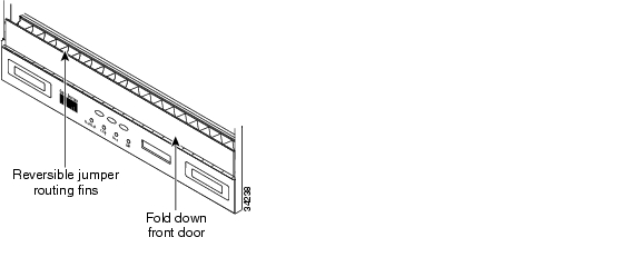
Figure 3-15 shows the cable management facilities that you can access through the fold-down front door, including the cable-routing channel and the jumper routing fins.
Figure 3-15 Managing cables on the front panel
3.11.1 Coaxial Cable Management
Coaxial cables connect to EIAs on the ONS 15454 backplane using cable connectors. EIAs feature cable-management eyelets for tie wrapping or lacing cables to the cover panel.
3.11.2 DS-1 Twisted-Pair Cable Management
Connect twisted pair/DS-1cables to SMB EIAs on the ONS 15454 backplane using cable connectors and DS-1 electrical interface adapters (baluns).
3.11.3 AMP Champ Cable Management
EIAs have cable management eyelets to tiewrap or lace cables to the cover panel. Tie wrap or lace the AMP Champ cables according to local site practice and route the cables. If you configure the ONS 15454 for a 23-inch rack, two additional inches of cable management area is available on each side of the shelf assembly.
![]()
![]()
![]()
![]()
![]()
![]()
![]()
![]()
Posted: Mon Feb 25 15:35:59 PST 2008
All contents are Copyright © 1992--2008 Cisco Systems, Inc. All rights reserved.
Important Notices and Privacy Statement.