|
|

Table Of Contents
2.1.2 Card and Power Requirements
2.2.1 TCC+ Card-Level Indicators
2.2.2 Network-Level Indicators
2.3.1 XC Card-Level Indicators
2.4.3 XCVT Card-Level Indicators
2.4.5 XCVT Card Specifications
2.5.3 XC10G Card-Level Indicators
2.5.4 XC/XCVT/XC10G Compatibility
2.5.5 XC10G Card Specifications
2.6 Alarm Interface Controller Card
Common Control Cards
This chapter describes Cisco ONS 15454 common control card functions. For installation and card turn-up procedures, refer to the Cisco ONS 15454 Procedure Guide.
Chapter topics include:
•
Alarm Interface Controller Card
2.1 Card Overview
The card overview section summarizes card functions, power consumption, temperature ranges, and compatibility.
Note
2.1.1 Common Control Cards
Table 2-1 lists five common control cards for the Cisco ONS 15454 and summarizes card functions.
Table 2-1 Common Control Card Functions
The TCC+ is the main processing center for the ONS 15454 and provides system initialization, provisioning, alarm reporting, maintenance, and diagnostics.
See the "TCC+ Card" section
The XC card is the central element for switching; it establishes connections and performs time division switching (TDS).
See the "XC Cross-Connect Card" section
The XCVT card is the central element for switching; it establishes connections and performs time division switching (TDS). The XCVT can manage STS and VT circuits up to 48c.
The XC10G card is the central element for switching; it establishes connections and performs time division switching (TDS). The XC10G can manage STS and VT circuits up to 192c. The XC10G allows up to four times the bandwidth of current XC and XCVT cards.
The AIC card provides customer-defined (environmental) alarms with its additional input/output alarm contact closures.
2.1.2 Card and Power Requirements
Table 2-2 lists power requirements for individual cards.
Note
2.1.3 Card Temperature Ranges
Table 2-3 shows C-Temp and I-Temp compliant cards and their product names.
Note
2.1.4 Card Compatibility
The tables below list ONS 15454 cards, compatible software versions, and compatible cross-connect cards. Read each card description for detailed information about the card. In the tables below, Yes means cards are compatible with the listed software versions and cross-connect cards. Table cells with dashes mean cards are not compatible with the listed software versions or cross-connect cards.
Table 2-4 Common-Control Card Software and Hardware Compatibility for the ONS 15454
Yes
Yes
Yes
Yes
Yes
Yes
Yes
Yes
Yes
Yes
Yes
Yes
Yes
Yes
Yes
Yes
Yes
—
Yes
Yes
Yes
Yes
Yes
Yes
Yes
Yes
—
—
—
—
Yes
Yes
Yes
—
—
Yes1
Yes
Yes
Yes
Yes
Yes
Yes
Yes
Yes
Yes
1 To enable OC-192 and OC-48 any slot card operation, use the XC10G card, the TCC+ card, Software R3.1 or higher, and the new 15454-SA-ANSI shelf assembly. Do not pair an XC or XCVT with an XC10G.
Table 2-5 Electrical Card Software and Cross-Connect Card Compatibility for the ONS 15454
Yes
Yes
Yes
Yes
Yes
Yes
Yes
Yes
Yes
Yes
Yes
Yes
Yes
Yes
Yes
Yes
Yes
Yes
Yes
Yes
Yes
Yes
Yes
Yes
Yes
Yes
Yes
Yes
Yes
Yes
Yes
Yes
Yes
Yes
Yes
Yes
Yes
Yes
Yes
Yes
Yes
Yes
Yes
Yes
Yes
—
Yes1
Yes
Yes
Yes
Yes
Yes
Yes
Yes
—
Yes 1
Yes
Yes
Yes
Yes
Yes
Yes
Yes
Yes
Yes
Yes
Yes
Yes
Yes
Yes
Yes
Yes
1 Use Software R3.0 or higher to enable all enhanced performance monitoring functions on the DS-3E cards. With Software R2.2.2, the DS-3E cards operate as the older DS-3 cards without enhanced performance monitoring.
Table 2-6 Optical Card Software and Cross-Connect Card Compatibility for the ONS 15454
Yes
Yes
Yes
Yes
Yes
Yes
Yes
Yes
Yes
Yes
Yes
Yes
Yes
Yes
Yes
Yes
Yes
Yes
Yes
Yes
Yes
Yes
Yes
Yes
Yes
Yes
Yes
Yes
Yes
Yes
Yes
Yes
Yes
Yes
Yes
Yes
Yes
Yes
Yes
Yes
Yes
Yes
Yes
Yes
Yes
Yes
Yes
Yes
Yes
Yes
Yes
Yes
Yes
Yes
Yes
Yes
Yes
Yes
Yes
Yes
Yes
Yes
Yes
Yes
Yes
Yes
Yes
Yes
Yes
Yes
Yes
Yes
No
No
No
No
No
Yes
No
No
Yes
Yes
Yes
Yes
Yes
Yes
Yes
Yes
Yes
Yes
Yes
Yes
Yes
Yes
Yes
Yes
Yes
Yes
Yes
—
—
—
Yes1
Yes
Yes
—
—
Yes 1
—
—
—
Yes 1
Yes
Yes
—
—
Yes 1
Yes
Yes
Yes
Yes
Yes
Yes
Yes
Yes
Yes
Yes
Yes
Yes
Yes
Yes
Yes
Yes
Yes
Yes
—
—
—
Yes 1
Yes
Yes
—
—
Yes 1
1 Use the XC10G card, the TCC+ card, Software R3.1 or higher and the new 15454-SA-ANSI shelf assembly to enable the OC48 IR/STM16 SH AS 1310, OC48 LR/STM16 LH AS 1550, and the OC192 LR/STM64 LH 1550 cards.
Table 2-7 Ethernet Card Software and Cross-Connect Card Compatibility for the ONS 15454
Yes
Yes
Yes
Yes
Yes
Yes
Yes
Yes
—
Yes
Yes
Yes
Yes
Yes
Yes
Yes
Yes
—
Yes
Yes
Yes
Yes
Yes
Yes
Yes
Yes
Yes1
Yes
Yes
Yes
Yes
Yes
Yes
Yes
Yes
Yes 1
No
No
No
No
Yes
Yes
Yes
Yes
Yes 1
1 To use Ethernet cards with the XC10G, select either the E100T-G card, the E1000-2-G card, or the G1000-4 card. Do not use the E100T-12 card or E1000-2 card with the XC10G.
2.2 TCC+ Card
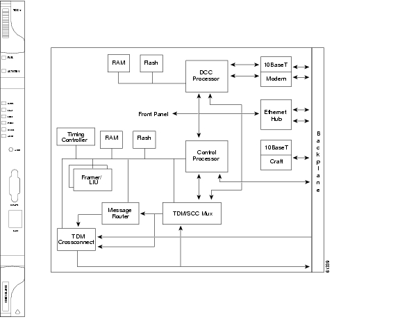
The TCC+ performs system initialization, provisioning, alarm reporting, maintenance, diagnostics, IP address detection/resolution, SONET Data Communications Channel (DCC) termination, and system fault detection for the ONS 15454. The TCC+ also ensures that the system maintains Telcordia timing requirements. Figure 2-1 shows the TCC+ faceplate and a block diagram of the card.
Figure 2-1 TCC+ faceplate and block diagram
The node database, IP address, and system software are stored in TCC+ non-volatile memory, which allows quick recovery in the event of a power or card failure.
The TCC+ supports multichannel, high-level data link control (HDLC) processing for the DCC. Up to 48 DCCs can be routed over the Serial Communication Interface (SCI) and terminated at the TCC+. The TCC+ selects and processes ten DCCs to facilitate remote system management interfaces.
The TCC+ performs all system-timing functions for each ONS 15454. The TCC+ monitors the recovered clocks from each traffic card and two DS-1 (BITS) interfaces for frequency accuracy. The TCC+ selects a recovered clock, a BITS, or an internal Stratum 3 reference as the system-timing reference. You can provision any of the clock inputs as primary or secondary timing sources. A slow-reference tracking loop allows the TCC+ to synchronize with the recovered clock, which provides holdover if the reference is lost.
Install TCC+ cards in Slots 7 and 11 for redundancy. If the active TCC+ fails, traffic switches to the protect TCC+. All TCC+ protection switches conform to protection switching standards of less than 50 ms.
The TCC+ features an RJ-45 10Base-T LAN port and an RS-232 DB9 type craft interface for user interfaces. The TL1 craft port runs at 9600 bps.
Caution
2.2.1 TCC+ Card-Level Indicators
The TCC+ faceplate has eight LEDs. The first two LEDs are card-level indicators.
2.2.2 Network-Level Indicators
The TCC+ faceplate has eight LEDs. Six LEDs are network-level indicators.
2.2.3 TCC+ Specifications
•
–
–
•
–
–
•
–
–
–
–
•
–
C-Temp (15454-TCC+): 0 to +55 degrees Celsius
I-Temp (15454-TCC+T): -40 to +65 degrees Celsius
–
–
•
–
–
•
–
2.3 XC Cross-Connect Card
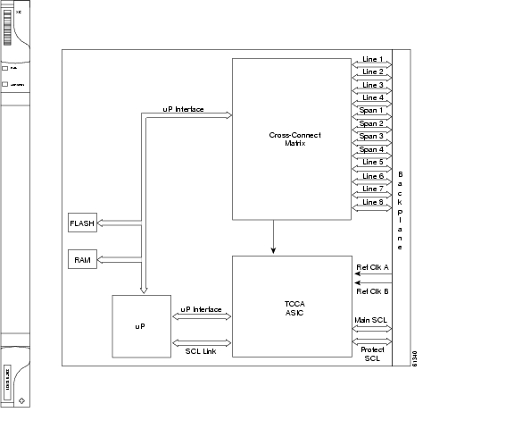
The cross-connect card is the central element for ONS 15454 switching. Available cross-connects are the XC, XCVT, and XC10G. The XC establishes connections and performs time division switching (TDS) at the STS-1 level between ONS 15454 traffic cards. The XC card faceplate and block diagram are shown in Figure 2-2. The cross-connect matrix is shown in Figure 2-3.
Figure 2-2 XC card faceplate and block diagram
The switch matrix on the XC card consists of 288 bidirectional ports. When creating bidirectional STS-1 cross-connects, each cross-connect uses two STS-1 ports. This results in 144 bidirectional STS-1 cross-connects. The switch matrix is fully crosspoint, non-blocking, and broadcast supporting. (Any STS-1 on any port can be connected to any other port, meaning that the STS cross-connections are non blocking.) This allows network operators to concentrate or groom low-speed traffic from line cards onto high-speed transport spans and to drop low-speed traffic from transport spans onto line cards.
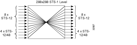
Figure 2-3 XC cross-connect matrix
The XC card has 12 input ports and 12 output ports. Four input and output ports operate at either STS-12 or STS-48 rates. The remaining eight input and output ports operate at the STS-12 rate. An STS-1 on any of the input ports can be mapped to an STS-1 output port, thus providing full STS-1 time slot assignments (TSA).
The XC card works with the TCC+ card to maintain connections and set up cross-connects within the ONS 15454. Either the XC, XCVT, or XC10G is required to operate the ONS 15454. You establish cross-connect and provisioning information through CTC. The TCC+ establishes the proper internal cross-connect information and relays the setup information to the cross-connect card.
Caution
For simplex operation, you can install a single XC card in Slots 8 or 10. A second XC should be added for redundancy. The card has no external interfaces. All cross-connect card interfaces are provided through the ONS 15454 backplane.
2.3.1 XC Card-Level Indicators
The XC card faceplate has two card-level LEDs.
2.3.2 XC Specifications
•
–
–
•
–
C-Temp (15454-XC): 0 to +55 degrees Celsius
I-Temp (15454-XC-T): -40 to +65 degrees Celsius
–
–
•
–
–
–
–
•
–
2.4 XCVT Cross-Connect Card
The XCVT card provides the same STS capability as a standard XC card and also provides VT cross-connection. The XCVT provides non-blocking STS-48 capacity to all of the high-speed slots and non-bidirectional blocking STS-12 capacity to all multispeed slots. Any STS-1 on any port can be connected to any other port, meaning that the STS cross-connections are non blocking.
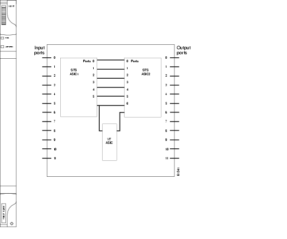
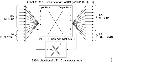
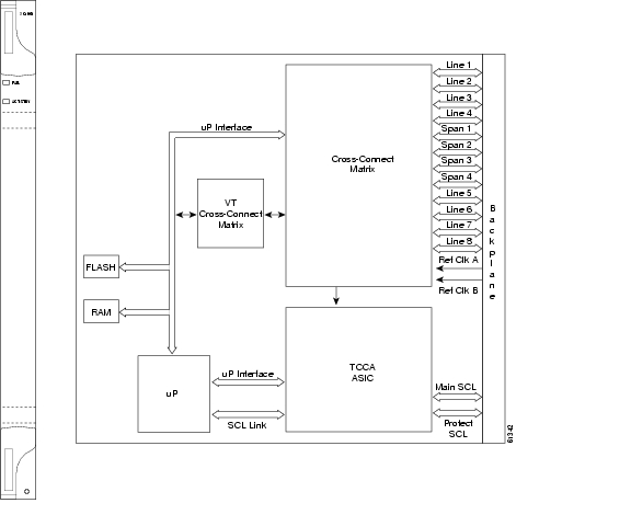
Figure 2-4 shows the XCVT faceplate and block diagram. Figure 2-5 shows the cross-connect matrix.
Figure 2-4 XCVT faceplate and block diagram
The STS-1 switch matrix on the XCVT card consists of 288 bidirectional ports and adds a VT matrix that can manage up to 336 bidirectional VT1.5 ports or the equivalent of a bidirectional STS-12. The VT1.5-level signals can be cross connected, dropped, or rearranged. The TCC+ assigns bandwidth to each slot on a per STS-1 or per VT1.5 basis. The switch matrices are fully crosspoint and broadcast supporting.
The XCVT card works with the TCC+ card to maintain connections and set up cross-connects within the node. Either the XCVT, XC10G, or XC is required to operate the ONS 15454. You can establish cross-connect (circuit) information through CTC. The TCC+ establishes the proper internal cross-connect information and relays the setup information to the XCVT card.
Caution
Figure 2-5 XCVT cross-connect matrix
2.4.1 VT Mapping
The VT structure is designed to transport and switch payloads below the DS-3 rate. The ONS 15454 performs Virtual Tributary (VT) mapping according to Telcordia GR-253 standards. Table 2-11 shows the VT numbering scheme for the ONS 15454 as it relates to the Telcordia standard.
2.4.2 XCVT Hosting DS3XM-6
The XCVT card works with DS3XM-6 (transmux) cards. A single DS3XM-6 can demultiplex (map down to a lower rate) six DS-3 signals into 168 VT1.5s that the XCVT card manages and cross connects. XCVT cards host a maximum of 336 bidirectional VT1.5s. In most network configurations, two DS3XM-6 cards are paired as working and protect cards.
2.4.3 XCVT Card-Level Indicators
The XCVT faceplate has two card-level LEDs.
2.4.4 XC/XCVT Compatibility
The XCVT card is compatible with the XC cards. The XCVT supports run-time compatibility with the XC cross-connect both within a single node and within a ring of mixed XCVT and XC nodes. However, working and protect cards within a single ONS 15454 must be either two XC cards or two XCVT cards. If an XC card or an XCVT card are used together as a working and protect pair, the XCVT acts as an XC card.
The XC and XCVT are supported in unidirectional path switched ring (UPSR) and bidirectional line switched ring (BLSR) configurations. VT and STS-level cross-connect and protection management are also supported in either type of ring. Nodes that rearrange or drop VTs must use an XCVT. Nodes that only rearrange or drop STSs can use an XC. You do not need to upgrade STS-only nodes to XCVT in a ring that can handle both VT and STS drop/rearrangement. In this scenario, however, the XC must run Software R2.0 or higher.
When upgrading from XC to XCVT cards, the first XCVT card installed acts as an XC card until the second XCVT card is installed.
To create an STS-capable ring that allows VT drops at some nodes, all of the nodes in the ring must first run Software R2.0 or higher. The nodes that allow VT drops must use XCVT, but the nodes that do not allow VT drops can use the XC or XCVT card.
2.4.5 XCVT Card Specifications
•
–
C-Temp (15454-XC-VT): 0 to +55 degrees Celsius
I-Temp (15454-XC-VT-T): -40 to +65 degrees Celsius
–
–
•
–
–
–
–
•
–
2.5 XC10G Cross-Connect Card
The XC10G card cross-connects STS-12, STS-48, and STS-192 signal rates. The XC10G allows up to four times the bandwidth of the XC and XCVT cards. The XC10G provides a maximum of 1152 STS-1 cross-connections. Any STS-1 on any port can be connected to any other port, meaning that the STS cross-connections are non blocking.
Figure 2-6 shows the XC10G faceplate and block diagram. Figure 2-7 shows the cross-connect matrix.
Figure 2-6 XC10G faceplate and block diagram
The XC10G card manages up to 336 bidirectional VT1.5 ports and 576 bidirectional STS-1 ports. The TCC+ assigns bandwidth to each slot on a per STS-1 or per VT1.5 basis.
Either the XC10G, XCVT, or XC is required to operate the ONS 15454. You can establish cross-connect (circuit) information through the Cisco Transport Controller (CTC). The TCC+ establishes the proper internal cross-connect information and sends the setup information to the cross-connect card.
Caution
Figure 2-7 XC10G cross-connect matrix
2.5.1 VT Mapping
The VT structure is designed to transport and switch payloads below the DS-3 rate. The Cisco ONS 15454 performs Virtual Tributary (VT) mapping according to Telcordia GR-253 standards. Table 2-13 shows the VT numbering scheme for the ONS 15454 as it relates to the Telcordia standard.
2.5.2 XC10G Hosting DS3XM-6
The XC10G card works with the DS3XM-6 (transmux) card. A single DS3XM-6 can demultiplex (map down to a lower rate) six DS-3 signals into 168 VT1.5s that the XC10G card manages and cross connects. XC10G cards host a maximum of 336 bidirectional VT1.5 ports. In most network configurations, two DS3XM-6 cards are paired as working and protect cards.
2.5.3 XC10G Card-Level Indicators
The XC10G faceplate has two card-level LEDs.
2.5.4 XC/XCVT/XC10G Compatibility
The XC10G supports the same features as the XC and XCVT cross-connects. The XC10G card is required for OC-192 and OC-48 any-slot operation. Do not use the XCVT or XC cards if you are using the OC-192 card, or if you placed one of the OC-48 any slot cards in a multispeed slot.
Note
The TCC+ card, Software R3.1 or higher and the new 15454-SA-ANSI shelf assembly are required for the operation of the XC10G. If you are using Ethernet cards, the E1000-2-G or the E100T-G must be used when the XC10G cross-connect card is in use. Do not pair an XC or XCVT with an XC10G. When upgrading from XC or XCVT to the XC10G card, refer to the Cisco ONS 15454 Procedure Guide for more information.
The upgrade procedure from the XC/XCVT cards to the XC10G card only applies to XC/XCVT cards that are installed in the 15454-SA-ANSI (Software R3.1 and later). You cannot perform this upgrade from shelves released prior to software R3.1. The XC10G requires the 15454-SA-ANSI.
2.5.5 XC10G Card Specifications
•
–
C-Temp (15454-XC-10G): 0 to +55 degrees Celsius
–
–
•
–
–
–
–
•
–
2.6 Alarm Interface Controller Card
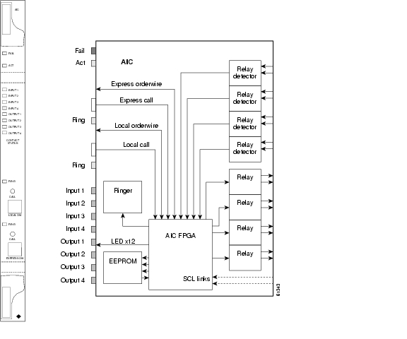
The optional Alarm Interface Controller (AIC) card provides customer-defined alarm input/output (I/O) and supports local and express orderwire. Figure 2-8 shows the AIC faceplate and a block diagram of the card. Figure 2-9 shows the RJ-11 cable.
Figure 2-8 AIC faceplate and block diagram
2.6.1 User-Defined Alarms
The AIC card provides input/output alarm contact closures. You can define up to four external alarms and four external controls. The physical connections are made using the backplane wire-wrap pins. The alarms are defined using CTC and TL1. For instructions, refer to the Cisco ONS 15454 Procedure Guide.
Each alarm contact has a corresponding LED on the front panel of the AIC that indicates the status of the alarm. External alarms (input contacts) are typically used for external sensors such as open doors, temperature sensors, flood sensors, and other environmental conditions. External controls (output contacts) are typically used to drive visual or audible devices such as bells and lights, but they can control other devices such as generators, heaters, and fans.
You can program each of the four input alarm contacts separately. Choices include Alarm on Closure or Alarm on Open, an alarm severity of any level (Critical, Major, Minor, Not Alarmed, Not Reported), a Service Affecting or Non-Service Affecting alarm-service level, and a 63-character alarm description for CTC display in the alarm log. You cannot assign the fan-tray abbreviation for the alarm; the abbreviation reflects the generic name of the input contacts. The alarm condition remains raised until the external input stops driving the contact or you provision the alarm input.
The output contacts can be provisioned to close on a trigger or to close manually. The trigger can be a local alarm severity threshold, a remote alarm severity, or a virtual wire:
•
•
•
You can also program the output alarm contacts (external controls) separately. In addition to provisionable triggers, you can manually force each external output contact to open or close. Manual operation takes precedence over any provisioned triggers that might be present.
2.6.2 Orderwire
Orderwire allows a craftsperson to plug a phoneset into an ONS 15454 and communicate with craftspeople working at other ONS 15454s or other facility equipment. The orderwire is a pulse code modulation (PCM) encoded voice channel that uses E1 or E2 bytes in section/line overhead.
The AIC allows simultaneous use of both local (section overhead signal) and express (line overhead channel) orderwire channels on a SONET ring or particular optics facility. Local orderwire also allows communication at regeneration sites when the regenerator is not a Cisco device.
You can provision orderwire functions with CTC similar to the current provisioning model for DCC channels. In CTC you provision the orderwire communications network during ring turn-up so that all NEs on the ring can reach one another. Orderwire terminations (i.e. the optics facilities that receive and process the orderwire channels) are provisionable. Both express and local orderwire can be configured as on or off on a particular SONET facility. The ONS 15454 supports up to four orderwire channel terminations per shelf. This allows linear, single ring, dual ring, and small hub-and-spoke configurations. Keep in mind that orderwire is not protected in ring topologies such as BLSR and UPSR.
Caution
The ONS 15454 implementation of both local and express orderwire is broadcast in nature. The line acts as a party line. There is no signalling for private point-to-point connections. Anyone who picks up the orderwire channel can communicate with all other participants on the connected orderwire subnetwork. The local orderwire party line is separate from the express orderwire party line. Up to four OC-N facilities for each local and express orderwire are provisionable as orderwire paths.
The AIC supports a "call" button on the module front panel which, when pressed, causes all ONS 15454 AICs on the orderwire subnetwork to "ring." The ringer/buzzer resides on the AIC. There is also a "ring" LED that mimics the AIC ringer. It flashes when any "call" button is pressed on the orderwire subnetwork. The "call" button and ringer/LED allow a remote craftsperson to get the attention of craftspeople across the network.
The orderwire ports are standard RJ-11 receptacles. The pins on the orderwire ports correspond to the tip and ring orderwire assignments.
Table 2-15 Orderwire Pin Assignments
1
Four-wire receive ring
2
Four-wire transmit tip
3
Two-wire ring
4
Two-wire tip
5
Four-wire transmit ring
6
Four-wire receive tip
When provisioning the orderwire subnetwork, make sure that an orderwire loop does not exist. Loops cause oscillation and an unusable orderwire channel.
Figure 2-9 RJ-11 cable
2.6.3 AIC Specifications
•
–
C-Temp (15454-AIC): 0 to +55 degrees Celsius
I-Temp (15454-AIC-T): -40 to +65 degrees Celsius
–
–
•
–
–
•
–
![]()
![]()
![]()
![]()
![]()
![]()
![]()
![]()
Posted: Mon Feb 25 15:34:49 PST 2008
All contents are Copyright © 1992--2008 Cisco Systems, Inc. All rights reserved.
Important Notices and Privacy Statement.