|
|

Table Of Contents
Cisco Transport Controller Operation
7.1.1 CTC Software Installed on the TCC+
7.1.2 CTC Software Installed on the PC or UNIX Workstation
7.7 Reverting to an Earlier Software Load
Cisco Transport Controller Operation
This chapter describes Cisco Transport Controller (CTC), the Cisco ONS 15454's software interface that is stored on the TCC+ card and downloaded to your workstation each time you log into the ONS 15454. For CTC set up and log-in information, refer to the Cisco ONS 15454 Procedure Guide.
Chapter topics include:
•
Reverting to an Earlier Software Load
7.1 CTC Software Versions
ONS 15454 provisioning and administration is performed using the Cisco Transport Controller software. CTC is a Java application that is installed in two locations:
•
•
7.1.1 CTC Software Installed on the TCC+
CTC software is pre-loaded on the ONS 15454 TCC+ cards; therefore, you do not need to install software on the TCC+. When a new CTC software version is released, follow procedures in the Cisco ONS 15454 Software Upgrade Guide Release 3.3 to upgrade the ONS 15454 software on the TCC+.
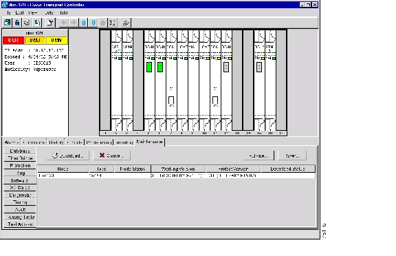
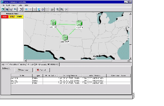
When you upgrade CTC software, the TCC+ stores the older CTC version as the protect CTC version, and the newer CTC release becomes the working version. You can view the software versions that are installed on an ONS 15454 by selecting the Maintenance > Software tabs in node view. Select the tabs in network view to display the software versions installed on all the network nodes.
Figure 7-1 CTC software versions displayed in node view
Figure 7-2 CTC software versions in displayed network view
7.1.2 CTC Software Installed on the PC or UNIX Workstation
CTC software is downloaded from the TCC+ and installed on your computer automatically after you connect to the ONS 15454. Downloading the CTC software files automatically ensures your computer is running the same CTC software version as the TCC+ you are accessing. The computer CTC software files are stored in the temporary directory designated by your computer's operating system. If the files are deleted, they are downloaded the next time you connect to an ONS 15454. Downloading the files takes 1-2 minutes.
7.2 CTC Installation Overview
To connect to an ONS 15454 using CTC, you enter the ONS 15454 IP address in the URL field of a web browser, such as Netscape Navigator or Microsoft Internet Explorer. After connecting to an ONS 15454, the following occurs automatically:
1.
2.
3.
4.
Each ONS 15454 can handle up to four network-level CTC sessions (the login node and its DCC-connected nodes) and one node-level session (login node only) at one time. CTC performance may vary, depending upon the volume of activity in each session.
Note
7.3 Computer Requirements
To use CTC in ONS 15454 Release 3.3, your computer must have a web browser with the correct Java Runtime Environment (JRE) installed. The correct JRE for each CTC software release is included on the Cisco ONS 15454 software CD. If you are running multiple CTC software releases on a network, the JRE installed on the computer must be compatible with the different software releases. Table 7-1 shows JRE compatibility with ONS software releases.
Requirements for PCs and UNIX workstations are provided in Table 7-2. A modified java.policy file must also be installed. In addition to Netscape Communicator and the JRE, also included on the ONS 15454 software CD and the ONS 15454 documentation CD are the Java plug-in and modified java.policy file.
7.4 The CTC Window
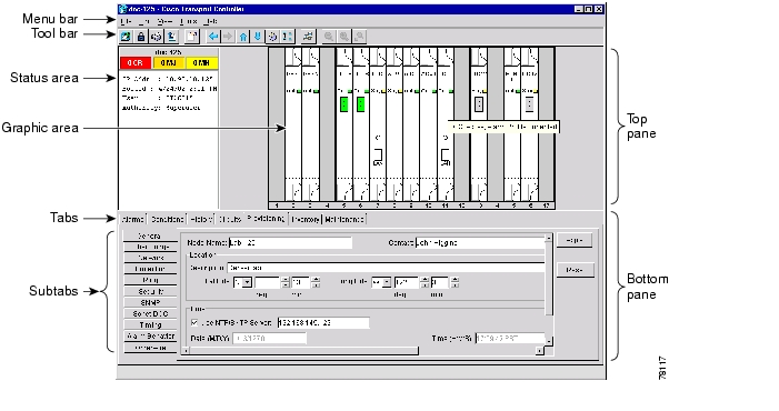
The CTC window (screen) displays after you log into an ONS 15454 ( Figure 7-3). The window includes a menu bar, toolbar, and a top and bottom pane. The top pane displays status information about the selected objects and a graphic of the current view. The bottom pane displays tabs and subtabs, which you use to view ONS 15454 information and perform ONS 15454 provisioning and maintenance. From this window you can display three ONS 15454 views: network, node, and card.
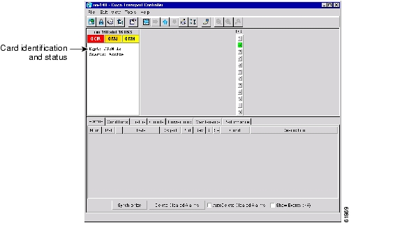
Figure 7-3 CTC window elements in the node view (default login view)
7.4.1 Node View
The CTC node view, shown in Figure 7-3, is the first view displayed after you log into an ONS 15454. The login node is the first node displayed, and it is the "home view" for the session. Node view allows you to view and manage one ONS 15454 node. The status area shows the node name, IP address, session boot date and time, number of critical (CR), major (MJ), and minor (MN) alarms, the name of the current logged-in user, and security level of the user.
7.4.1.1 CTC Card Colors
The graphic area of the CTC window depicts the ONS 15454 shelf assembly. The colors of the cards in the graphic reflect the real-time status of the physical card and slot ( Table 7-3).
7.4.1.2 Node View Card Shortcuts
If you move your mouse over cards in the graphic, popups display additional information about the card including the card type, card status (active or standby), the number of critical, major, and minor alarms (if any), and the alarm profile used by the card. Right-clicking a card reveals a shortcut menu, which you can use to open, reset, or delete a card. Right-click a slot (grey) to pre-provision a card (i.e., provision a slot before installing the card).
7.4.1.3 Node View Tabs
Table 7-4 lists the tabs and subtabs available in the node view.
7.4.2 Network View
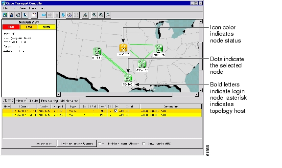
Network view ( Figure 7-4) allows you to view and manage ONS 15454s that have DCC connections to the node that you logged into and any login node groups you may have selected.
Note
The graphic area displays a background image with colored ONS 15454 icons. The icon colors indicate the node status ( Table 7-5). Green lines show DCC connections between the nodes. Selecting a node or span in the graphic area displays information about the node and span in the status area.
Figure 7-4 A four-node network displayed in CTC network view
The node colors displayed in network view indicate the status of the node.
7.4.3 Card View
Card view displays information about individual ONS 15454 cards and is the window where you perform card-specific maintenance and provisioning ( Figure 7-5). A graphic of the selected card is shown in the graphic area. The status area displays the node name, slot, number of alarms, card type, equipment type, and either the card status (active or standby) or port status (IS [in service] or OOS [out of service]). The information that is displayed and the actions you can perform depend on the card.
Note
Card view provides access to the following tabs: Alarms, History, Circuits, Provisioning, Maintenance, Performance, and Conditions. (The Performance tab is not displayed for the AIC card.) The subtabs, fields, and information displayed under each tab depend on the card type selected.
Figure 7-5 CTC card view showing an DS3N-12 card
7.5 TCC+ Reset
You can reset the ONS 15454 TCC+ cards by using the Cisco Transport Controller (CTC) software, or by physically reseating a TCC+ card (card pull). Resetting the TCC+ using CTC reboots the TCC+ and reloads the operating system and the application software. Additionally, a card pull reset temporarily removes power from the TCC+ and clears all buffer memory.
You can apply a CTC reset to either an active or standby TCC+ without affecting traffic, but you should only perform a card pull on a standby TCC+. If you need to perform a card pull on an active TCC+, put the TCC+ into standby mode first by performing a reset using CTC on the card.
Note
7.6 The TCC+ Database
When dual TCC+ cards are installed in the ONS 15454, each TCC+ card hosts a separate database; therefore, the protect card's database is available if the database on the working TCC+ fails. You can also store a back-up version of the database on the workstation running CTC. This operation should be part of a regular ONS 15454 maintenance program at approximately weekly intervals, and should also be completed when preparing an ONS 15454 for a pending natural disaster, such as a flood or fire.
Note
7.7 Reverting to an Earlier Software Load
Prior to Release 2.2.1, the ONS 15454 could not revert to an earlier software database without deleting the current database and losing both cross-connect and DCC connectivity. The revert would result in a loss of traffic until the user manually restored the previous database or recreated the existing circuits and provisioning.
Reverting to a 2.2.1 or later load will switch to the older software load and its attendant database without affecting traffic or DCC connectivity. This feature requires dual TCC+ cards and CTC software Release 2.2.1 or later as the protect version.
When you click the Activate button after a software upgrade, the TCC+ copies the current working database and saves it in a reserved location in the TCC+ flash memory. If you later need to revert to the original working software load from the protect software load, the saved database installs automatically. You do not need to restore the database manually or recreate circuits.
Tip
Note
Circuits created and provisioning performed after a software load is activated (upgraded to a higher software release) will not reinstate with a revert. The database configuration at the time of activation is reinstated after a revert. This does not apply to maintenance reverts (e.g. 2.2.2 to 2.2.1), because maintenance releases use the same database.
![]()
![]()
![]()
![]()
![]()
![]()
![]()
![]()
Posted: Mon Feb 25 15:37:43 PST 2008
All contents are Copyright © 1992--2008 Cisco Systems, Inc. All rights reserved.
Important Notices and Privacy Statement.