|
|

Table Of Contents
5.2 Bidirectional Line Switched Rings
5.2.6 Upgrading From Two-Fiber to Four-Fiber BLSRs
5.2.7 Adding and Removing BLSR Nodes
5.3 Unidirectional Path Switched Rings
5.3.1 Example UPSR Application
5.3.3 Adding and Removing UPSR Nodes
5.6 Path-Protected Mesh Networks
SONET Topologies
This chapter explains how to set up the Cisco ONS 15454 in different SONET topologies, including:
•
Two-fiber and four-fiber bidirectional line switched rings (BLSRs)
•
•
•
•
5.1 Before You Begin
To avoid errors during network configuration, Cisco recommends that you draw the complete ONS 15454 SONET topology on paper (or electronically) before you begin the physical implementation. A sketch ensures that you have adequate slots, cards, and fibers to complete the topology.
Table 5-1 shows the SONET rings that can be created on each ONS 15454 node.
Table 5-1 ONS 15454 Rings
All rings
5
BLSRs
2
2-Fiber BLSR
2
4-Fiber BLSR
1
UPSR
4
5.2 Bidirectional Line Switched Rings
The ONS 15454 can support two concurrent BLSRs in one of the following configurations:
•
•
Each BLSR can have up to 16 ONS 15454s. Because the working and protect bandwidths must be equal, you can create only OC-12 (two-fiber only), OC-48, or OC-192 BLSRs.
Note
5.2.1 Two-Fiber BLSRs
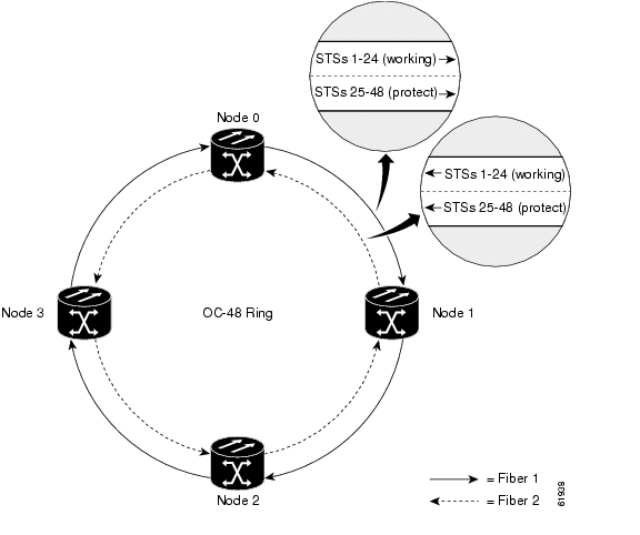
In two-fiber BLSRs, each fiber is divided into working and protect bandwidths. For example, in an OC-48 BLSR ( Figure 5-1), STSs 1 - 24 carry the working traffic, and STSs 25 - 48 are reserved for protection. Working traffic (STSs 1 - 24) travels in one direction on one fiber and in the opposite direction on the second fiber. The Cisco Transport Controller (CTC) circuit routing routines calculate the "shortest path" for circuits based on many factors, including requirements set by the circuit provisioner, traffic patterns, and distance. For example, in Figure 5-1, circuits going from Node 0 to Node 1 typically will travel on Fiber 1, unless that fiber is full, in which case circuits will be routed on Fiber 2 through Node 3 and Node 2. Traffic from Node 0 to Node 2 (or Node 1 to Node 3), may be routed on either fiber, depending on circuit provisioning requirements and traffic loads.
Figure 5-1 A four-node, two-fiber BLSR
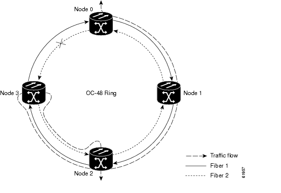
The SONET K1 and K2 bytes carry the information that governs BLSR protection switches. Each BLSR node monitors the K bytes to determine when to switch the SONET signal to an alternate physical path. The K bytes communicate failure conditions and actions taken between nodes in the ring.
If a break occurs on one fiber, working traffic targeted for a node beyond the break switches to the protect bandwidth on the second fiber. The traffic travels in reverse direction on the protect bandwidth until it reaches its destination node. At that point, traffic is switched back to the working bandwidth.
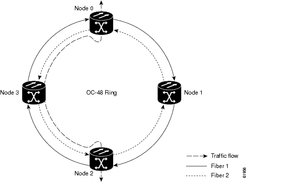
Figure 5-2 shows a sample traffic pattern on a four-node, two-fiber BLSR.
Figure 5-2 Four-node, two-fiber BLSR sample traffic pattern
Figure 5-3 shows how traffic is rerouted following a line break between Node 0 and Node 3.
•
•
Figure 5-3 Four-node, two-fiber BLSR traffic pattern following line break
5.2.2 Four-Fiber BLSRs
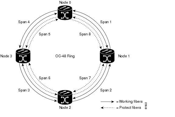
Four-fiber BLSRs double the bandwidth of two-fiber BLSRs. Because they allow span switching as well as ring switching, four-fiber BLSRs increase the reliability and flexibility of traffic protection. Two fibers are allocated for working traffic and two fibers for protection, as shown in Figure 5-4. To implement a four-fiber BLSR, you must install four OC-48 or OC-48AS cards, or four OC-192 cards at each BLSR node.
Figure 5-4 A four-node, four-fiber BLSR
Four-fiber BLSRs provide span and ring switching:
•
•
Figure 5-5 A four-fiber BLSR span switch
Figure 5-6 A four-fiber BLSR ring switch
5.2.3 BLSR Bandwidth
BLSR nodes can terminate traffic that is fed from either side of the ring. Therefore, BLSRs are suited for distributed node-to-node traffic applications such as interoffice networks and access networks.
BLSRs allow bandwidth to be reused around the ring and can carry more traffic than a network with traffic flowing through one central hub. BLSRs can also carry more traffic than a UPSR operating at the same OC-N rate. Table 5-2 shows the bidirectional bandwidth capacities of two-fiber BLSRs. The capacity is the OC-N rate divided by two, multiplied by the number of nodes in the ring minus the number of pass-through STS-1 circuits. Table 5-3 shows the bidirectional bandwidth capacities of four-fiber BLSRs.
Table 5-2 Two-Fiber BLSR Capacity
OC-12
STS1-6
STS 7-12
OC-48
STS 1-24
STS 25-48
24 x N - PT
OC-192
STS 1-96
STS 97-192
96 x N - PT
1 N equals the number of ONS 15454 nodes configured as BLSR nodes.
2 PT equals the number of STS-1 circuits passed through ONS 15454 nodes in the ring (capacity can vary depending on the traffic pattern).
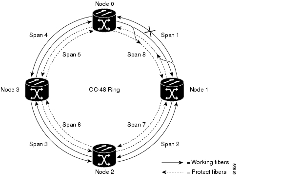
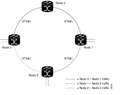
Figure 5-7 shows an example of BLSR bandwidth reuse. The same STS carries three different traffic sets simultaneously on different spans on the ring: one set from Node 3 to Node 1, one from Node 1 to Node 2, and another from Node 2 to Node 3.
Figure 5-7 BLSR bandwidth reuse
5.2.4 Sample BLSR Application
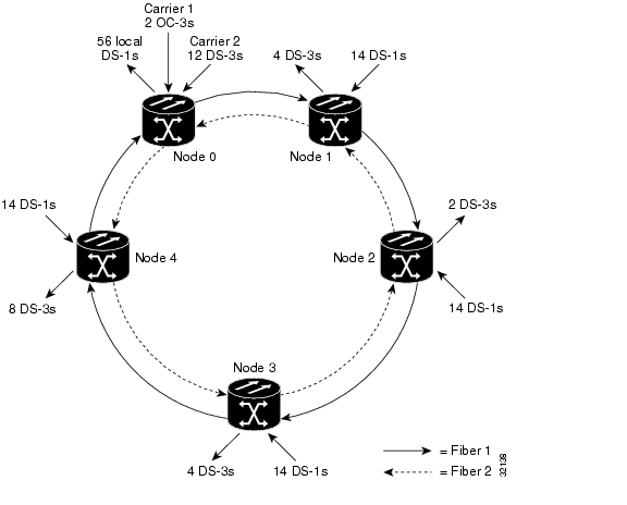
Figure 5-8 shows a sample two-fiber BLSR implementation. A regional long-distance network connects to other carriers at Node 0. Traffic is delivered to the service provider's major hubs.
•
•
•
Figure 5-8 A five-node BLSR
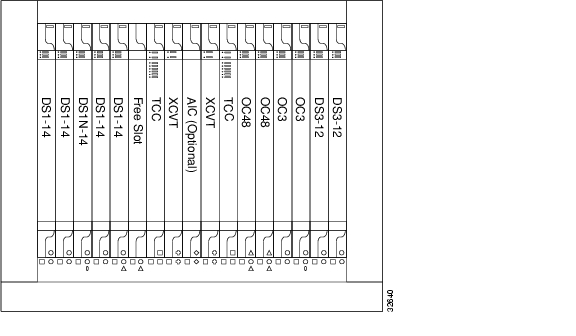
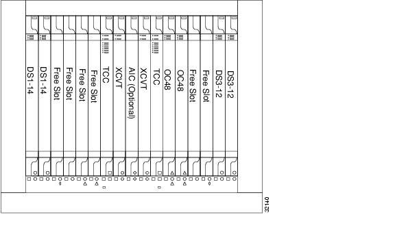
Figure 5-9 shows the shelf assembly layout for Node 0, which has one free slot. Figure 5-10 shows the shelf assembly layout for the remaining sites in the ring. In this BLSR configuration, an additional eight DS-3s at Node IDs 1 and 3 can be activated. An additional four DS-3s can be added at Node ID 4, and ten DS-3s can be added at Node ID 2. Each site has free slots for future traffic needs.
Figure 5-9 Shelf assembly layout for Node 0 in Figure 5-8
Figure 5-10 Shelf assembly layout for Nodes 1 - 4 in Figure 5-8
5.2.5 Setting Up BLSRs
To set up a BLSR on the ONS 15454, you perform five basic procedures:
•
•
•
•
•
Procedure: Install the BLSR Trunk Cards
Step 1
Step 2
Step 3
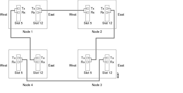
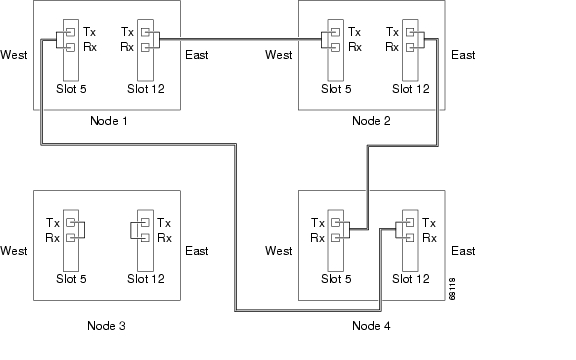
Plan your fiber connections and use the same plan for all BLSR nodes. For example, make the east port the farthest slot to the right and the west port the farthest left. Plug fiber connected to an east port at one node into the west port on an adjacent node. Figure 5-11 shows fiber connections for a two-fiber BLSR with trunk cards in Slot 5 (west) and Slot 12 (east).
Note
For four-fiber BLSRs, use the same east - west connection pattern for the working and protect fibers. Do not mix working and protect card connections. The BLSR will not function if working and protect cards are interconnected. Figure 5-12 shows fiber connections for a four-fiber BLSR. Slot 5 (west) and Slot 12 (east) carry the working traffic. Slot 6 (west) and Slot 13 (east) carry the protect traffic.
Figure 5-11 Connecting fiber to a four-node, two-fiber BLSR
Figure 5-12 Connecting fiber to a four-node, four-fiber BLSR
Procedure: Create the BLSR DCC Terminations
Step 1
Step 2
Step 3
Step 4
Step 5
Step 6
Step 7
Note
Procedure: Enable the BLSR Ports
Step 1
Step 2
Step 3
Step 4
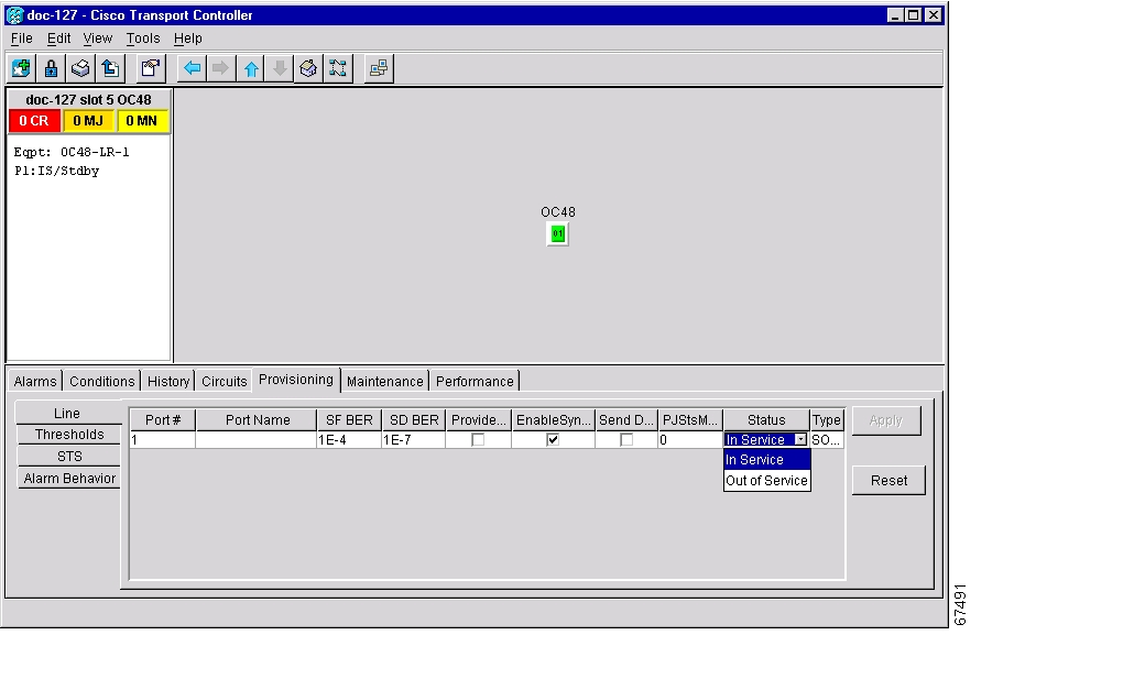
Figure 5-13 Enabling an optical port
Step 5
Step 6
Step 7
After configuring the SONET DCC, set the timing for the node. For procedures, see the "Setting Up ONS 15454 Timing" section on page 3-12. After you configure the timing you can provision the BLSR.
Procedure: Provision the BLSR
Step 1
Step 2
Step 3
Step 4
•
•
•
•
•
•
The east and west ports must match the fiber connections and DCC terminations set up in the "Install the BLSR Trunk Cards" procedure and the "Create the BLSR DCC Terminations" procedure.
For four-fiber BLSRs, complete the following:
•
•
•
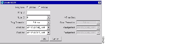
Figure 5-14 Setting BLSR properties
Step 5
Note
Step 6
Step 7
Note
Step 8
Step 9
Step 10
•
•
Step 11
a.
b.
c.
d.
e.
f.
g.
5.2.6 Upgrading From Two-Fiber to Four-Fiber BLSRs
Two-fiber OC-48 or OC-192 BLSRs can be upgraded to four-fiber BLSRs. To upgrade, you install two OC-48 or OC-192 cards at each two-fiber BLSR node, then log into CTC and upgrade each node from two-fiber to four-fiber. The fibers that were divided into working and protect bandwidths for the two-fiber BLSR are now fully allocated for working BLSR traffic.
Procedure: Upgrade From a Two-Fiber to a Four-Fiber BLSR
Step 1
a.
b.
c.
If trouble is indicated, for example, a major alarm exists, resolve the problem before proceeding to Step 2. See the Cisco ONS 15454 Troubleshooting and Maintenance Guide for additional information.
Step 2
Step 3
a.
b.
c.
d.
e.
Step 4
Step 5
Step 6
a.
b.
c.
d.
Step 7
a.
b.
c.
–
–
–
d.
e.
Step 8
a.
b.
c.
d.
e.
Step 9
5.2.7 Adding and Removing BLSR Nodes
This section explains how to add and remove BLSR nodes. To add or remove a node, you force a protection switch to route traffic away from the span where you will add or remove the node. Figure 5-15 shows a three-node BLSR before the new node is added. To add Node 3, you would:
•
•
•
Note
Figure 5-15 A three-node BLSR before adding a new node
Procedure: Add a BLSR Node
Perform these steps on-site and not from a remote location.
Step 1
Step 2
•
•
•
If trouble is indicated, for example, a major alarm exists, resolve the problem before proceeding.
Step 3
Step 4
•
•
•
•
Step 5
Step 6
a.
b.
Performing a FORCE switch generates a manual switch request on an equipment (MANUAL-REQ) alarm. This is normal.
Caution
Step 7
Step 8
a.
b.
Step 9
a.
b.
Step 10
Figure 5-16 A BLSR with a newly-added fourth node
Step 11
Step 12
Step 13
Step 14
Step 15
Step 16
Step 17
Step 18
a.
b.
Procedure: Remove a BLSR Node
Caution
Step 1
•
•
Step 2
Step 3
•
•
•
If trouble is indicated, for example, a critical or major alarm exists, resolve the problem before proceeding.
Step 4
Step 5
a.
b.
c.
d.
Step 6
a.
b.
c.
d.
e.
f.
Step 7
Caution
a.
b.
c.
d.
e.
f.
Step 8
Step 9
Step 10
Step 11
10 - 15 seconds, select the Provisioning > Ring tabs and click Ring Map.) When the dialog box displays, click Yes.Step 12
Step 13
a.
b.
c.
d.
Step 14
5.2.8 Moving BLSR Trunk Cards
Caution
Caution
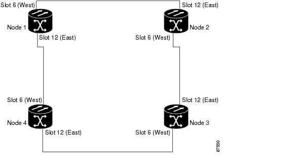
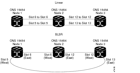
Figure 5-17 shows a four node OC-48 BLSR using trunk cards in Slots 6 and 12 at all four nodes. Trunk cards will be moved at Node 4 from Slots 6 and 12 to Slots 5 and 6. To do this Node 4 is temporarily removed from the active BLSR while the trunk cards are switched.
Figure 5-17 A four-node BLSR before a trunk card switch
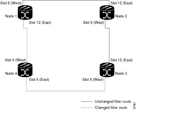
Figure 5-18 shows the BLSR after the cards are switched.
Figure 5-18 A four-node BLSR after the trunk cards are switched at one node
Procedure: Move a BLSR Trunk Card
Use the following steps to move one BLSR trunk card to a different slot. Use this procedure for each card you want to move. Although the procedure is for OC-48 BLSR trunk cards, you can use the same procedure for OC-12, OC-48AS, and OC-192 cards.
Note
Step 1
•
•
•
If trouble is indicated, for example, a critical or major alarm exists, resolve the problem before proceeding. Refer to the Cisco ONS 15454 Troubleshooting and Maintenance Guide for alarm troubleshooting procedures.
Step 2
a.
b.
When you perform a manual switch, a manual switch request equipment alarm (MANUAL-REA) is generated. This is normal.
Caution
c.
d.
Step 3
Step 4
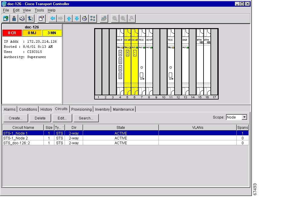
Figure 5-19 Deleting circuits from a BLSR trunk card
Step 5
a.
b.
c.
Step 6
a.
b.
Step 7
a.
b.
c.
Step 8
Step 9
a.
b.
Step 10
Step 11
Step 12
Step 13
a.
b.
c.
d.
Step 14
Step 15
Step 16
5.3 Unidirectional Path Switched Rings
UPSRs provide duplicate fiber paths around the ring. Working traffic flows in one direction and protection traffic flows in the opposite direction. If a problem occurs in the working traffic path, the receiving node switches to the path coming from the opposite direction.
CTC automates ring configuration. UPSR traffic is defined within the ONS 15454 on a circuit-by-circuit basis. If a path-protected circuit is not defined within a 1+1 or BLSR line protection scheme and path protection is available and specified, CTC uses UPSR as the default.
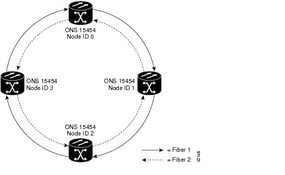
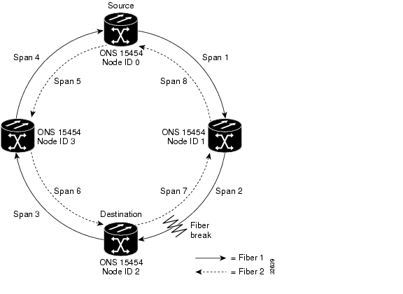
Figure 5-20 shows a basic UPSR configuration. If Node ID 0 sends a signal to Node ID 2, the working signal travels on the working traffic path through Node ID 1. The same signal is also sent on the protect traffic path through Node ID 3. If a fiber break occurs ( Figure 5-21), Node ID 2 switches its active receiver to the protect signal coming through Node ID 3.
Because each traffic path is transported around the entire ring, UPSRs are best suited for networks where traffic concentrates at one or two locations and is not widely distributed. UPSR capacity is equal to its bit rate. Services can originate and terminate on the same UPSR, or they can be passed to an adjacent access or interoffice ring for transport to the service-terminating location.
Figure 5-20 A basic four-node UPSR
Figure 5-21 A UPSR with a fiber break
5.3.1 Example UPSR Application
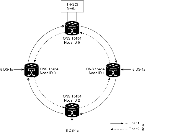
Figure 5-22 shows a common UPSR application. OC-3 optics provide remote switch connectivity to a host TR-303 switch. In the example, each remote switch requires eight DS-1s to return to the host switch. Figure 5-23 and Figure 5-24 show the shelf layout for each site.
Figure 5-22 An OC-3 UPSR
Node ID 0 has four DS1-14 cards to provide 56 active DS-1 ports. The other sites only require two DS1-14 cards to handle the eight DS-1s to and from the remote switch. You can use the other half of each ONS 15454 shelf assembly to provide support for a second or third ring to other existing or planned remote sites.
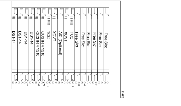
In this sample OC-3 UPSR, Node ID 0 contains four DS1-14 cards and two OC3 IR 4 1310 cards. Six free slots also exist in this setup and can be provisioned with cards or left empty. Figure 5-23 shows the shelf setup for these cards.
Figure 5-23 Layout of Node ID 0 in the OC-3 UPSR example (Figure 5-15)
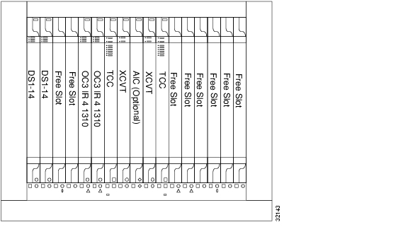
In the Figure 5-22 example, Nodes IDs 1 - 3 each contain two DS1-14 cards and two OC3 4 IR 1310 cards. Eight free slots exist. They can be provisioned with other cards or left empty. Figure 5-24 shows the shelf assembly setup for this configuration sample.
Figure 5-24 Layout of Node IDs 1 - 3 in the OC-3 UPSR example (Figure 5-15)
5.3.2 Setting Up a UPSR
To set up a UPSR, you perform four basic procedures:
•
•
•
•
After you enable the ports, you set up the UPSR circuits. UPSR signal thresholds—the levels that determine when the UPSR path is switched—are set at the circuit level. To create UPSR circuits, see the "Circuits Overview" section on page 6-1.
Procedure: Install the UPSR Trunk Cards
Step 1
Step 2
Step 3
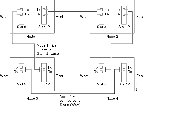
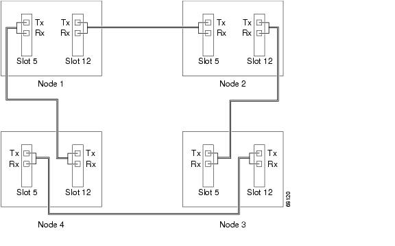
To avoid errors, make the east port the farthest slot to the right and the west port the farthest left. Fiber connected to an east port at one node must plug into the west port on an adjacent node. Figure 5-25 shows fiber connections for a four-node UPSR with trunk cards in Slot 5 (west) and Slot 12 (east).
Always plug the fiber plugged into the transmit (Tx) connector of an OC-N card at one node into the receive (Rx) connector of an OC-N card at the adjacent node. The card will display an SF LED if Tx and Rx fibers are mismatched.
Figure 5-25 Connecting fiber to a four-node UPSR
Procedure: Configure the UPSR DCC Terminations
Step 1
Step 2
Step 3
Step 4
Note
Step 5
The slots/ports display in the SDCC Terminations section.
Step 6
After configuring the SONET DCC, set the timing for the node. For procedures, see the "Setting Up ONS 15454 Timing" section on page 3-12. After configuring the timing, enable the UPSR ports as described in the following procedure.
Procedure: Enable the UPSR Ports
Step 1
Step 2
Step 3
Step 4
Step 5
Step 6
You configured a UPSR for one node. Use the same procedures to configure the additional nodes. To create path-protected mesh networks, see the "Path-Protected Mesh Networks" section. To create circuits, see the "Circuits Overview" section on page 6-1.
5.3.3 Adding and Removing UPSR Nodes
This section explains how to add and remove nodes in an ONS 15454 UPSR configuration. To add or remove a node, you switch traffic on the affected spans to route traffic away from the area of the ring where service will be performed. Use the span selector switch option to switch traffic from a UPSR span at different protection levels. The span selector switch option is useful when you need to reroute traffic from a UPSR span temporarily to add or drop nodes, perform maintenance, or perform other operations.
Procedure: Switch UPSR Traffic
Step 1
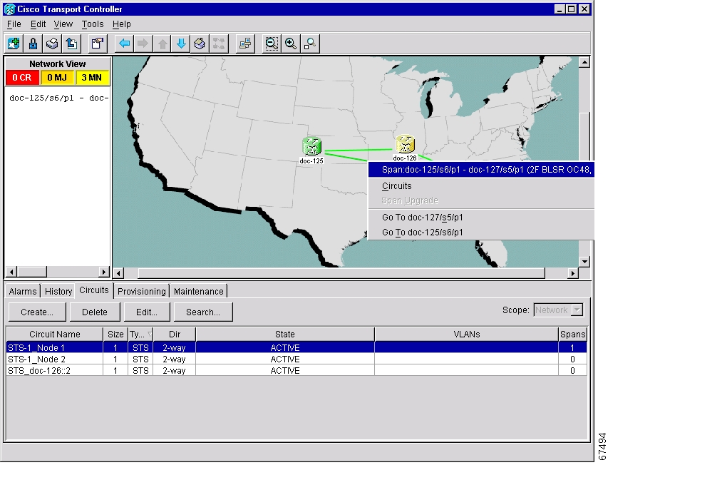
Step 2
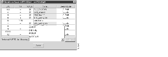
Figure 5-26 Using the span shortcut menu to display circuits
Step 3
•
•
•
•
Caution
Figure 5-27 Switching UPSR circuits
Step 4
Step 5
Step 6
Procedure: Add a UPSR Node
Note
Step 1
•
•
•
•
If trouble is indicated, for example, a critical or major alarm exists, resolve the problem before proceeding.
Step 2
•
•
•
Step 3
Step 4
Caution
Step 5
a.
b.
Step 6
Note
Step 7
Step 8
Step 9
Step 10
Step 11
Step 12
Procedure: Remove a UPSR Node
Caution
Step 1
•
•
•
•
If trouble is indicated, for example, a critical or major alarm exists, resolve the problem before proceeding.
Step 2
Caution
Step 3
a.
b.
c.
d.
Step 4
Step 5
Step 6
Step 7
Note
Step 8
5.4 Subtending Rings
The ONS 15454 supports up to ten SONET DCCs. Therefore, one ONS 15454 node can terminate and groom any one of the following ring combinations:
•
•
•
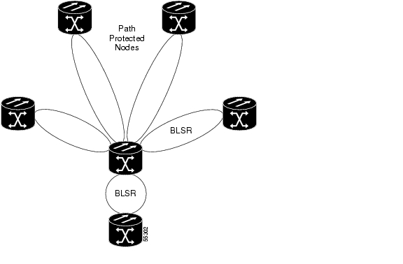
Subtending rings from an ONS 15454 reduces the number of nodes and cards required and reduces external shelf-to-shelf cabling. Figure 5-28 shows an ONS 15454 with multiple subtending rings.
Figure 5-28 An ONS 15454 with multiple subtending rings
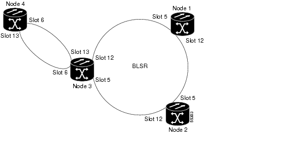
Figure 5-29 shows a UPSR subtending from a BLSR. In this example, Node 3 is the only node serving both the BLSR and UPSR. OC-N cards in Slots 5 and 12 serve the BLSR, and OC-N cards in Slots 6 and 13 serve the UPSR.
Figure 5-29 A UPSR subtending from a BLSR
Procedure: Subtend a UPSR from a BLSR
This procedure requires an established BLSR and one BLSR node with OC-N cards and fibers to carry the UPSR. The procedure also assumes you can set up a UPSR. (For UPSR setup procedures, see the "Setting Up a UPSR" section.)
Step 1
Step 2
Step 3
Step 4
Step 5
Step 6
The selected slots/ports are displayed in the SDCC Terminations section.
Step 7
a.
b.
c.
d.
Step 8
Step 9
Procedure: Subtend a BLSR from a UPSR
This procedure requires an established UPSR and one UPSR node with OC-N cards and fibers to connect to the BLSR. The procedure also assumes you can set up a BLSR. (For BLSR setup procedures, see the "Setting Up BLSRs" section.)
Step 1
Step 2
Step 3
Step 4
Step 5
Step 6
Step 7
Step 8
a.
b.
c.
d.
Step 9
Step 10
Step 11
The ONS 15454 can support two BLSRs on the same node. This capability allows you to deploy an ONS 15454 in applications requiring SONET DCSs (digital cross connect systems) or multiple SONET ADMs (add/drop multiplexers).
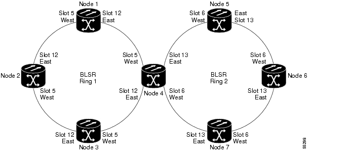
Figure 5-30 shows two BLSRs shared by one ONS 15454. Ring 1 runs on Nodes 1, 2, 3, and 4. Ring 2 runs on Nodes 4, 5, 6, and 7. Two BLSR rings, Ring 1 and Ring 2, are provisioned on Node 4. Ring 1 uses cards in Slots 5 and 12, and Ring 2 uses cards in Slots 6 and 13.
Note
Figure 5-30 A BLSR subtending from a BLSR
After subtending two BLSRs, you can route circuits from nodes in one ring to nodes in the second ring. For example in Figure 5-30, you can route a circuit from Node 1 to Node 7. The circuit would normally travel from Node 1 to Node 4 to Node 7. If fiber breaks occur, for example between Nodes 1 and 4 and Nodes 4 and 7, traffic is rerouted around each ring: in this example, Nodes 2 and 3 in Ring 1 and Nodes 5 and 6 in Ring 2.
Procedure: Subtend a BLSR from a BLSR
This procedure requires an established BLSR and one BLSR node with OC-N cards and fibers to carry the BLSR. The procedure also assumes you know how to set up a BLSR. For BLSR setup procedures, see the "Setting Up BLSRs" section.
Step 1
Step 2
Step 3
Step 4
Step 5
Step 6
Step 7
Step 8
a.
b.
c.
d.
Step 9
Step 10
Step 11
Figure 5-31 shows an example of two subtending BLSRs.
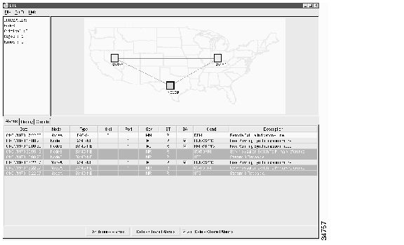
Figure 5-31 Viewing subtending BLSRs on the network map
Figure 5-32 shows the Ring subtab for Node 5, which is the node that carries the two rings.
Figure 5-32 Configuring two BLSRs on the same node
5.5 Linear ADM Configurations
You can configure ONS 15454s as a line of add/drop multiplexers (ADMs) by configuring one set of OC-N cards as the working path and a second set as the protect path. Unlike rings, linear (point-to-point) ADMs require that the OC-N cards at each node be in 1+1 protection to ensure that a break to the working line is automatically routed to the protect line.
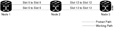
Figure 5-33 shows three ONS 15454s in a linear ADM configuration. Working traffic flows from Slot 6/Node 1 to Slot 6/Node 2, and from Slot 12/Node 2 to Slot 12/Node 3. You create the protect path by placing Slot 6 in 1+1 protection with Slot 5 at Nodes 1 and 2, and Slot 12 in 1+1 protection with Slot 13 at Nodes 2 and 3.
Figure 5-33 A linear (point-to-point) ADM configuration
Procedure: Create a Linear ADM
Complete the following steps for each node that will be included in the linear ADM.
Step 1
Step 2
Step 3
Step 4
a.
b.
c.
Note
Step 5
Step 6
a.
b.
c.
Repeat Step 6 for each OC-N card connected to the linear ADM.
Procedure: Convert a Linear ADM to UPSR
The following procedures describe how to convert a three-node linear ADM to a UPSR. You will need a SONET test set to monitor traffic while you perform these procedures.
Caution
Caution
Step 1
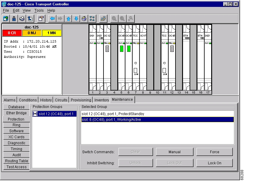
Step 2
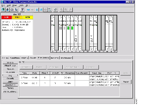
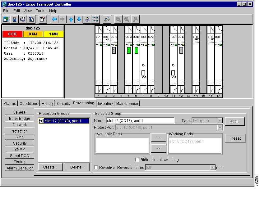
Figure 5-34 Verifying working slots in a protection group
Step 3
Step 4
a.
a.
b.
c.
d.
e.
Step 5
Step 6
Note
a.
b.
c.
d.
e.
Figure 5-35 Deleting a protection group
Step 7
Figure 5-36 Converting a linear ADM to a UPSR
Step 8
If you are leaving the OC-N cards in place, go to Step 13. If you are removing the cards, complete Steps 9 - 12. (In this example, cards in Node 2/Slots 5 and 13 are removed.)
Step 9
a.
b.
c.
Step 10
a.
b.
c.
d.
Step 11
a.
b.
–
–
See the "Printing and Exporting CTC Data" section on page 2-26 for more information.
Step 12
Step 13
Step 14
Step 15
Step 16
Step 17
An EOC SDCC alarm will occur until an SDCC termination is created on the adjacent node.
Step 18
Step 19
Note
You can create the circuits automatically or manually. However, circuits must be protected. When they were built in the linear ADM, they were protected by the protect path on Node 1/Slot 5 to Node 2/Slot 5 to Node 3/Slot 13. With the new UPSR, circuits should also be created with protection.
Deleting the first circuit and recreating it to the same card/port should restore the circuit immediately.
Step 20
Step 21
Although the cursor only shows the first circuit created, do not become alarmed that the other circuits are not present. Verify with the SONET test set that the original circuits and the new circuits are operational. The original circuits were created on the counter clockwise linear path.
Step 22
Figure 5-37 A UPSR displayed in network view
Procedure: Convert a Linear ADM to a BLSR
The following procedures describe how to convert a three-node linear ADM to a BLSR. You will need a SONET test set to monitor traffic while you perform these procedures.
Caution
Caution
Step 1
Step 2
Step 3
Step 4
a.
a.
b.
c.
d.
e.
Step 5
Step 6
a.
b.
c.
d.
Note
Step 7
Figure 5-38 Converting a linear ADM to a BLSR
Step 8
If you are leaving the OC-N cards in place, go to Step 13. If you are removing the cards, complete Steps 9 - 12. (In this example, cards in Node 2/Slots 5 and 13 are removed.)
Step 9
a.
b.
c.
Step 10
a.
b.
c.
d.
Step 11
a.
b.
–
–
See the "Printing and Exporting CTC Data" section on page 2-26 for more information.
Step 12
Step 13
Step 14
Step 15
Step 16
Step 17
Step 18
a.
b.
c.
Note
Step 19
Be sure to assign the same Ring ID and different node IDs to all nodes in the BLSR. Do not accept the BLSR ring map until all nodes are provisioned.
Note
Step 20
5.6 Path-Protected Mesh Networks
In addition to single BLSRs, UPSRs and ADMs, you can extend ONS 15454 traffic protection by creating path-protected mesh networks (PPMNs). PPMNs include multiple ONS 15454 SONET topologies and extend the protection provided by a single UPSR to the meshed architecture of several interconnecting rings. In a PPMN, circuits travel diverse paths through a network of single or multiple meshed rings. When you create circuits, you can have CTC automatically route circuits across the PPMN, or you can manually route them. You can also choose levels of circuit protection. For example, if you choose full protection, CTC creates an alternate route for the circuit in addition to the main route. The second route follows a unique path through the network between the source and destination and sets up a second set of cross-connections.
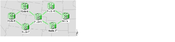
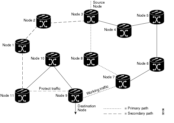
For example, in Figure 5-39, a circuit is created from Node 3 to Node 9. CTC determines that the shortest route between the two nodes passes through Node 8 and Node 7, shown by the dotted line, and automatically creates cross-connections at Nodes, 3, 8, 7, and 9 to provide the primary circuit path.
If full protection is selected, CTC creates a second unique route between Nodes 3 and 9 which, in this example, passes through Nodes 2, 1, and 11. Cross-connections are automatically created at Nodes, 3, 2, 1, 11, and 9, shown by the dashed line. If a failure occurs on the primary path, traffic switches to the second circuit path. In this example, Node 9 switches from the traffic coming in from Node 7 to the traffic coming in from Node 11 and service resumes. The switch occurs within 50 ms.
Figure 5-39 A path-protected mesh network
PPMN also allows spans of different SONET line rates to be mixed together in "virtual rings." Figure 5-40 shows Nodes 1, 2, 3, and 4 in a standard OC-48 ring. Nodes 5, 6, 7, and 8 link to the backbone ring through OC-12 fiber. The "virtual ring" formed by Nodes 5, 6, 7, and 8 uses both OC-48 and OC-12.
Figure 5-40 A PPMN virtual ring
![]()
![]()
![]()
![]()
![]()
![]()
![]()
![]()
Posted: Fri Feb 22 16:25:42 PST 2008
All contents are Copyright © 1992--2008 Cisco Systems, Inc. All rights reserved.
Important Notices and Privacy Statement.