cc/td/doc/product/ong/15400/454rel31
hometocprevnextglossaryfeedbacksearchhelp
PDF

Table Of Contents

Circuits and Tunnels

6.1 Circuits Overview

6.2 Creating Circuits and VT Tunnels

6.3 Creating Multiple Drops for Unidirectional Circuits

6.4 Creating Monitor Circuits

6.5 Searching for Circuits

6.6 Editing UPSR Circuits

6.7 Creating a Path Trace

6.8 Cross-Connect Card Capacities

6.8.1 VT1.5 Cross-Connects

6.8.2 VT Tunnels

6.9 Creating DCC Tunnels


Circuits and Tunnels


This chapter explains how to create and administer Cisco ONS 15454 circuits and tunnels, which includes:

Creating standard STS and VT1.5 circuits

Creating VT tunnels

Creating multiple drop circuits

Creating monitor circuits

Editing UPSR circuits

Creating path traces to monitor traffic

Reviewing ONS 15454 cross-connect card capacities

Creating DCC tunnels to tunnel third-party equipment through ONS 15454 networks

6.1 Circuits Overview

You can create STS and VT1.5 circuits across and within ONS 15454 nodes and assign different attributes to circuits, for example:

Create one-way, two-way, or broadcast circuits.

Assign user-defined names to circuits.

Assign different circuit sizes. STS circuits can be STS-1, STS-3c, STS-12c, STS-48c, or STS-192c. Ethernet circuits can be STS-1, STS-3c, STS-6c, or STS-12c. (To create Ethernet circuits see the "Provision a Shared Packet Ring" procedure on page 9-10.)

Route circuits automatically or manually.

Automatically create multiple circuits.

Require the circuit path to be fully protected.

Require protected source and destination cards and ports.

Define a secondary circuit source or destination that allows you to interoperate an ONS 15454 unidirectional path switched ring (UPSR) with third-party equipment UPSRs.


Note In this chapter, "cross-connect" and "circuit" have the following meanings: Cross-connect refers to the connections that occur within a single ONS 15454 to allow a circuit to enter and exit an ONS 15454. Circuit refers to the series of connections from a traffic source (where traffic enters the ONS 15454 network) to the drop or destination (where traffic exits an ONS 15454 network).


6.2 Creating Circuits and VT Tunnels

This section explains how to create STS and VT1.5 circuits and VT tunnels. For an explanation and examples of circuits and VT tunnels, see the "Cross-Connect Card Capacities" section. You can create unidirectional or bidirectional, revertive or non-revertive circuits. You can have circuits routed automatically or you can manually route them. The auto range feature eliminates the need to individually build circuits of the same type; CTC can create additional sequential circuits if you specify the number of circuits you need and build the first circuit.

You can provision circuits at any of the following points:

Before cards are installed. The ONS 15454 allows you to provision slots and circuits before installing the traffic cards. (To provision an empty slot, right-click it and select a card from the shortcut menu.) However, circuits will not carry traffic until you install the cards and place their ports in service. For procedures, see the "Install Optical, Electrical, and Ethernet Cards" procedure on page 1-48 and the "Enable Ports" procedure on page 3-10.

Cards are installed; ports are out of service. You must place the ports in service before circuits will carry traffic.

Cards are installed, and their ports are in service. Circuits will carry traffic as soon as the signal is received.

Procedure: Create an Automatically Routed Circuit


Note If you want to route circuits on protected drops, create the card protection groups before creating circuits. See the "Create Protection Groups" procedure on page 3-9.


Step 1 Log into an ONS 15454 and click the Circuits tab.


Tip You can also right-click a source node in network view, select Provision Circuit To, and choose the circuit destination node from the menu.


Step 2 Click Create.

Step 3 In the Circuit Creation dialog box ( Figure 6-1), complete the following fields:

Name—(optional) Assign a name to the circuit. The name can be alphanumeric and up to 32 characters (including spaces). If you leave the Name field blank, CTC assigns a default name to the circuit.

Type—Select the type of circuit you want to create: STS, VT (VT1.5), or VT tunnel. The circuit type determines the circuit-provisioning options that are displayed. See the "VT1.5 Cross-Connects" section and the "VT Tunnels" section for more information.

Size—Select the circuit size (STS circuits only). The "c" indicates concatenated STSs.

Bidirectional—Check this box to create a two-way circuit; uncheck it to create a one-way circuit (STS and VT circuits only; VT tunnels are bidirectional).

Number of circuits—Type the number of circuits you want to create. If you enter more than 1, you can use auto-ranging to create the additional circuits automatically. Otherwise, CTC returns to the Circuit Source page after you create each circuit until you finish creating the number of circuits specified here.

Auto Ranged—If selected, and you select the source and destination of one circuit, CTC automatically determines the source and destination for the remaining Number of circuits and creates the circuits. To determine the source and destination, CTC increments the most specific part of the end points. An end point can be a port, an STS, or a VT/DS-1. If CTC runs out of choices, or selects an end point that is already in use, CTC stops and allows you to either select a valid end point or cancel. If you select a valid end point and continue, auto-ranging begins after you click Finish for the current circuit.

Protected Drops—If this box is checked, CTC only displays protected cards and ports (1:1, 1:N, 1+1 or BLSR protection) as choices for the circuit source and destination.

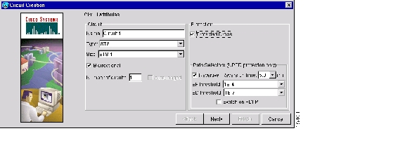
Figure 6-1 Creating a circuit

Step 4 (UPSR circuits only) Set the UPSR Selector Defaults:

Revertive—Check this box if you want traffic to revert to the working path when the conditions that diverted it to the protect path are repaired. If Revertive is not chosen, traffic remains on the protect path after the switch.

Reversion time—If Revertive is checked, set the reversion time. This is the amount of time that will elapse before the traffic reverts to the working path. Traffic can revert when conditions causing the switch are cleared (the default reversion time is 5 minutes).

SF threshold—Set the UPSR path-level signal failure bit error rate (BER) thresholds (STS circuits only).

SD threshold—Set the UPSR path-level signal degrade BER thresholds (STS circuits only).

Switch on PDI-P—Check this box if you want traffic to switch when an STS payload defect indicator is received (STS circuits only).

Step 5 Click Next.

Step 6 In the Circuit Source dialog box, set the circuit source.

Options include node, slot, port, STS, and VT/DS-1. The options that display depend on the circuit type and circuit properties you selected in Step 3 and the cards installed in the node. For example, if you are creating a VT circuit or tunnel, only nodes with XCVT and XC10G cards are displayed. For Ethergroups, see the "Ethernet Circuit Configurations" section on page 9-6.

Click Use Secondary Source if you need to create a UPSR bridge/selector circuit entry point in a multivendor UPSR.

Step 7 Click Next.

Step 8 In the Circuit Destination dialog box, enter the appropriate information for the circuit destination. If the circuit is bidirectional, you can click Use Secondary Destination if you need to create a UPSR bridge/selector circuit destination point in a multivendor UPSR. (To add secondary destinations to unidirectional circuits, see "Create a Unidirectional Circuit with Multiple Drops" procedure.)

Step 9 Click Next.

Step 10 Under Circuit Routing Preferences ( Figure 6-2), select Route Automatically. The following options (described in detail in the next step) are available:

Using Required Nodes/Spans—If selected, you can specify nodes and spans to include or exclude in the CTC-generated circuit route.

Review Route Before Creation—If selected, you can review and edit the circuit route before the circuit is created.

Step 11 If you want the circuit routed on a protected path, select Fully Protected Path. Otherwise, go to
Step 12. CTC creates a primary and alternate circuit route (virtual UPSR) based on the nodal diversity option you select:

Nodal Diversity Required—Ensures that the primary and alternate paths within path-protected mesh network (PPMN) portions of the complete circuit path are nodally diverse. (For information about PPMN, see the "Path-Protected Mesh Networks" section on page 5-50.)

Nodal Diversity Desired—Specifies that node diversity should be attempted, but if node diversity is not possible, CTC creates link diverse paths for the PPMN portion of the complete circuit path.

Link Diversity Only—Specifies that only link-diverse primary and alternate paths for PPMN portions of the complete circuit path are needed. The paths may be node-diverse, but CTC does not check for node diversity.

Figure 6-2 Setting circuit routing preferences

Step 12 Click Finish or Next depending on whether you selected Using Required Nodes/Spans and/or Review Route Before Creation:

Using Required Nodes/Spans—If selected, click Next to display the Circuit Route Constraints panel ( Figure 6-3). On the circuit map, click a node or span and click Include (to include the node or span in the circuit) or Exclude (to exclude the node/span from the circuit). The order in which you select included nodes and spans sets the circuit sequence. Click spans twice to change the circuit direction. After you add the spans and nodes, you can use the Up and Down buttons to change their order, or click Remove to remove a node or span. When you are finished, click Finish or Next, depending on whether you selected Review Route Before Creation.

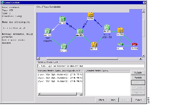
Figure 6-3 Specifying circuit constraints

Review Route Before Creation—If selected, click Next to display the route for you to review. To add or delete a circuit span, select a node on the circuit route. Blue arrows show the circuit route. Green arrows indicate spans that you can add. Click a span arrowhead, then click Include to include the span or Remove to remove the span.

When you click Finish, CTC creates the circuit and returns to the Circuits window. If you entered more than 1 in Number of Circuits in the Circuit Attributes dialog box in Step 3, the Circuit Source dialog box is displayed so you can create the remaining circuits. If Auto Ranged is checked, CTC automatically creates the number of sequential circuits that you entered in Number of Circuits. Otherwise, go on to
Step 13.

Step 13 If you are provisioning circuits before installing the traffic cards and enabling their ports, you must install the cards and enable the ports before circuits will carry traffic. For procedures, see the "Install Optical, Electrical, and Ethernet Cards" procedure on page 1-48 and the "Enable Ports" procedure on page 3-10.


Procedure: Create a Manually Routed Circuit


Note If you want to route circuits on protected drops, create the card protection groups before creating circuits. See the "Create Protection Groups" procedure on page 3-9.


Step 1 Log into an ONS 15454 and click the Circuits tab.


Tip You can also right-click a source node in network view, select Provision Circuit To, and choose the circuit destination node from the menu.


Step 2 Click Create.

Step 3 In the Circuit Creation dialog box ( Figure 6-1), complete the following fields:

Name—(optional) Assign a name to the circuit. The name can be alphanumeric and up to 32 characters (including spaces). If you leave the Name field blank, CTC assigns a default name to the circuit.

Type—Select the type of circuit you want to create: STS, VT (VT1.5), or VT tunnel. The circuit type determines the circuit-provisioning options that are displayed. "VT1.5 Cross-Connects" section and the "VT Tunnels" section for more information.

Size—Select the circuit size (STS circuits only). The "c" indicates concatenated STSs.

Bidirectional—Check this box to create a two-way circuit; uncheck it to create a one-way circuit (STS and VT circuits only; VT tunnels are bidirectional).

Number of circuits—Type the number of circuits you want to create. CTC returns to the Circuit Source page after you create each circuit until you finish creating the number of circuits specified here.

Auto Ranged—This option is not available with manual circuit routing.

Protected Drops—If this box is checked, CTC only displays protected cards and ports (1:1, 1:N, 1+1 or BLSR protection) as choices for the circuit source and destination.

Figure 6-4 Creating a circuit

Step 4 (UPSR circuits only) Set the UPSR Selector Defaults:

Revertive—Check this box if you want traffic to revert to the working path when the conditions that diverted it to the protect path are repaired. If Revertive is not chosen, traffic remains on the protect path after the switch.

Reversion time—If Revertive is checked, set the reversion time. This is the amount of time that will elapse before the traffic reverts to the working path. Traffic can revert when conditions causing the switch are cleared (the default reversion time is 5 minutes).

SF threshold—Set the UPSR path-level signal failure bit error rate (BER) thresholds (STS circuits only).

SD threshold—Set the UPSR path-level signal degrade BER thresholds (STS circuits only).

Switch on PDI-P—Check this box if you want traffic to switch when an STS payload defect indicator is received (STS circuits only).

Step 5 Click Next.

Step 6 In the Circuit Source dialog box, set the circuit source.

Options include node, slot, port, STS, and VT/DS-1. The options that display depend on the circuit type and circuit properties you selected in Step 3 and the cards installed in the node. For example, if you are creating a VT circuit or tunnel, only nodes with XCVT and XC10G cards are displayed. For Ethergroups, see the "Ethernet Circuit Configurations" section on page 9-6.

Click Use Secondary Source if you need to create a UPSR bridge/selector circuit entry point in a multivendor UPSR.

Step 7 Click Next.

Step 8 In the Circuit Destination dialog box, enter the appropriate information for the circuit destination. If the circuit is bidirectional, you can click Use Secondary Destination if you need to create a UPSR bridge/selector circuit destination point in a multivendor UPSR. (To add secondary destinations to unidirectional circuits, see "Create a Unidirectional Circuit with Multiple Drops" procedure.)

Step 9 Click Next.

Step 10 Under Circuit Routing Preferences ( Figure 6-2), de-select Route Automatically.

Step 11 If you want the circuit routed on a protected path, select Fully Protected Path. Otherwise, go to Step 12. CTC creates a primary and alternate circuit route (virtual UPSR) based on the nodal diversity option you select:

Nodal Diversity Required—Ensures that the primary and alternate paths within path-protected mesh network (PPMN) portions of the complete circuit path are nodally diverse. (For information about PPMN, see the "Path-Protected Mesh Networks" section on page 5-50.)

Nodal Diversity Desired—Specifies that node diversity should be attempted, but if node diversity is not possible, CTC creates link diverse paths for the PPMN portion of the complete circuit path.

Link Diversity Only—Specifies that only link-diverse primary and alternate paths for PPMN portions of the complete circuit path are needed. The paths may be node-diverse, but CTC does not check for node diversity.

Step 12 Click Next. The Route Review and Edit panel is displayed for you to manually route the circuit. The green arrows pointing from the source node to other network nodes indicate spans that are available for routing the circuit.

Step 13 Set the circuit route:

a. Click the arrowhead of the span you want the circuit to travel.

b. If you want to change the source STS or VT, change it in the Source STS or Source VT fields.

c. Click Add Span.

The span is added to the Included Spans list and the span arrow turns blue.

Step 14 Repeat Step 13 until the circuit is provisioned from the source to the destination node.

When provisioning a protected circuit, you only need to select one path of BLSR or 1+1 spans from the source to the drop. If you select unprotected spans as part of the path, select two different paths for the unprotected segment of the path.

Step 15 When the circuit is provisioned, click Finish.

If you entered more than 1 in Number of Circuits in the Circuit Attributes dialog box in Step 3, the Circuit Source dialog box is displayed so you can create the remaining circuits.

Step 16 If you are provisioning circuits before installing the traffic cards and enabling their ports, you must install the cards and enable the ports before circuits will carry traffic. For procedures, see the "Install Optical, Electrical, and Ethernet Cards" procedure on page 1-48 and the "Enable Ports" procedure on page 3-10.


6.3 Creating Multiple Drops for Unidirectional Circuits

Unidirectional circuits can have multiple drops for use in broadcast circuit schemes. In broadcast scenarios, one source transmits traffic to multiple destinations, but traffic is not returned back to the source.

When you create a unidirectional circuit, the card that does not have its backplane Rx input terminated with a valid input signal generates a loss of service (LOS) alarm. To mask the alarm, create an alarm profile suppressing the LOS alarm and apply it to the port that does not have its Rx input terminated. See the "Creating and Modifying Alarm Profiles" section on page 10-9 for information.

Procedure: Create a Unidirectional Circuit with Multiple Drops


Step 1 Use the "Create an Automatically Routed Circuit" procedure to create a circuit. To make it unidirectional, clear the Bidirectional check box on the Circuit Creation dialog box.

Step 2 After the unidirectional circuit is created, in node or network view select the Circuits tab.

Step 3 Select the unidirectional circuit and click Edit (or double-click the circuit).

Step 4 On the Drops tab of the Edit Circuits dialog box, click Create or, if Show Detailed Map is selected, right-click a node on the circuit map and select Add Drop.

Step 5 On the Define New Drop dialog box, complete the appropriate fields to define the new circuit drop: Node, Slot, Port, STS, VT (if applicable).

Step 6 Click OK.

Step 7 If you need to create additional drops, repeat Steps 4 - 6. If not, click Close.

Step 8 Verify the new drops on the Edit Circuit map:

If Show Detailed Map is selected: a "D" enclosed by circles appears on each side of the node graphic.

If Show Detailed Map is not selected: "Drop #1, Drop #2" appear under the node graphic.


6.4 Creating Monitor Circuits

You can set up secondary circuits to monitor traffic on primary bidirectional circuits. Figure 6-5 shows an example of a monitor circuit. At Node 1, a VT1.5 is dropped from Port 1 of an EC1-12 card. To monitor the VT1.5 traffic, test equipment is plugged into Port 2 of the EC1-12 card and a monitor circuit to Port 2 is provisioned in CTC. Circuit monitors are one-way. The monitor circuit in Figure 6-5 is used to monitor VT1.5 traffic received by Port 1 of the EC1-12 card.


Note Monitor circuits cannot be used with EtherSwitch circuits.


Note For unidirectional circuits, create a drop to the port where the test equipment is attached.


Figure 6-5 A VT1.5 monitor circuit received at an EC1-12 port

Procedure: Create a Monitor Circuit


Step 1 Log into CTC.

Step 2 In node view, select the Circuits tab.

Step 3 Select the bidirectional circuit that you want to monitor. Click Edit.

Step 4 On the Edit Circuit dialog box, click the Monitors tab.

Step 5 The Monitors tab displays ports that you can use to monitor the circuit selected in Step 3.

Step 6 On the Monitors tab, select a port. The monitor circuit displays traffic coming into the node at the card/port you select. In Figure 6-5, you would select either the DS1-14 card (to test circuit traffic entering Node 2 on the DS1-14) or the OC-N card at Node 1 (to test circuit traffic entering Node 1 on the OC-N card).

Step 7 Click Create Monitor Circuit.

Step 8 On the Circuit Creation dialog box, select the destination node, slot, port, and STS for the monitored circuit. In the Figure 6-5 example, this is Port 2 on the EC1-12 card. Click Next.

Step 9 On the Circuit Creation dialog box confirmation, review the monitor circuit information. Click Finish.

Step 10 On the Edit Circuit dialog box, click Close. The new monitor circuit displays on the Circuits tab.


6.5 Searching for Circuits

CTC provides the ability to search for ONS 15454 circuits based on circuit name. Searches can be conducted at the network, node, and card level. You can search for whole words and include capitalization as a search parameter.

Procedure: Search for ONS 15454 Circuits


Step 1 Log into CTC.

Step 2 Switch to the appropriate CTC view:

Network view to conduct searches at the network level

Node view to conduct searches at the network or node level

Card view to conduct searches at the card, node, or network level

Step 3 Click the Circuits tab.

Step 4 If you are in Node or Card view, select the scope for the search in the Scope field.

Step 5 Click Search.

Step 6 In the Circuit Name Search dialog box, complete the following:

Find What—Enter the text of the circuit name you want to find.

Match Whole Word Only—If checked, CTC selects circuits only if the entire word matches the text in the Find What field.

Match Case—If checked, CTC selects circuits only when the capitalization matches the capitalization entered in the Find What field.

Direction—Select the direction for the search. Searches are conducted up or down from the currently selected circuit.

Step 7 Click Find Next.

Step 8 Repeat Steps 6 and 7 until you are finished, then click Cancel.


6.6 Editing UPSR Circuits

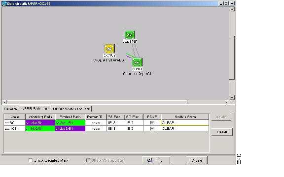
Use the Edit Circuits window to change UPSR selectors and switch protection paths ( Figure 6-6). In this window, you can:

View the UPSR circuit's working and protection paths

Edit the reversion time

Edit the Signal Fail/Signal Degrade thresholds

Change PDI-P settings, perform maintenance switches on the circuit selector, and view switch counts for the selectors

Display a map of the UPSR circuits to better see circuit flow between nodes

Figure 6-6 Editing UPSR selectors

Procedure: Edit a UPSR Circuit


Step 1 Log into the source or drop node of the UPSR circuit.

Step 2 Click the Circuits tab.

Step 3 Click the circuit you want to edit, then click Edit.

Step 4 On the Edit Circuit window, click the UPSR tab.

Step 5 Edit the UPSR selectors:

Reversion Time—Controls whether traffic reverts to the working path when conditions that diverted it to the protect path are repaired. If you select Never, traffic does not revert. Selecting a time sets the amount of time that will elapse before traffic reverts to the working path.

SF Ber Level—Sets the UPSR signal failure BER threshold (STS circuits only).

SD Ber Level—Sets the UPSR signal degrade BER threshold (STS circuits only).

PDI-P—When checked, traffic switches if an STS payload defect indication is received (STS circuits only).

Switch State—Switches circuit traffic between the working and protect paths. The color of the Working Path and Protect Path fields indicates the active path. Normally, the Working Path is green and the Protect Path is purple. If the Protect Path is green, working traffic has switched to the Protect Path.

CLEAR—Removes a previously-set switch command.

LOCKOUT OF PROTECT—Prevents traffic from switching to the protect circuit path.

FORCE TO WORKING—Forces traffic to switch to the working circuit path, regardless of whether the path is error free.

FORCE TO PROTECT—Forces traffic to switch to the protect circuit path, regardless of whether the path is error free.

MANUAL TO WORKING—Switches traffic to the working circuit path when the working path is error free.

MANUAL TO PROTECT—Switches traffic to the protect circuit path when the protect path is error free.


Caution The FORCE and LOCKOUT commands override normal protection switching mechanisms. Applying these commands incorrectly can cause traffic outages.

Step 6 Click Apply, then check that the selector switches as you expect.


6.7 Creating a Path Trace

The SONET J1 Path Trace is a repeated, fixed-length string comprised of 64 consecutive J1 bytes. You can use the string to monitor interruptions or changes to circuit traffic. Table 6-1 shows the ONS 15454 cards that support path trace. DS-1 and DS-3 cards can transmit and receive the J1 field, while the EC-1, OC-3, OC-48AS, and OC-192 can only receive it. Cards not listed in the table do not support the J1 byte.

Table 6-1 ONS 15454 Cards Supporting J1 Path Trace

Card
Receive
Transmit

DS1-14

X

X

DS1N-14

X

X

DS3-12E

X

X

DS3N-12E

X

X

DS3XM-6X

X

X

EC1-12

X


OC3 IR 4 1310

X


OC48 IR/STM16 SH AS 1310

X


OC48 LR/STM16 LH AS 1550

X


OC192 LR/STM64 LH 1550

X


The J1 path trace transmits a repeated, fixed-length string. If the string received at a circuit drop port does not match the string the port expects to receive, an alarm is raised. Two path trace modes are available:

Automatic—The receiving port assumes the first J1 string it receives is the baseline J1 string.

Manual—The receiving port uses a string that you manually enter as the baseline J1 string.

Table 6-2 shows the general flow for setting up the J1 path trace. To set up a path trace on an ONS 15454 circuit, follow the steps in the "Create a J1 Path Trace" procedure.

Table 6-2 Path Trace Source and Drop Provisioning

Step
Port
Action
Notes

1

Source

Edit the path-trace transmit string.

If not edited, an empty string is transmitted.

2

Drop

Edit the path-trace transmit string.

If not edited, an empty string is transmitted.

3

Source

Edit the path-trace expected string.

Only if Path Trace mode is set to Manual, and only on DS-1, DS3E, and DS3XM cards.

4

Drop

Edit the path-trace expected string

Only Path Trace mode is set to Manual, and only on DS-1, DS3E, and DS3XM cards.

5

Drop

Change Path Trace Mode

Automatic or Manual.

6

Source

Change Path Trace Mode

Automatic or Manual.


Procedure: Create a J1 Path Trace

To perform this procedure, you must have an STS circuit using a DS-1, DS3E, or DS3XM card at the circuit source and drop ports, or an STS circuit passing through an EC-1, OC-3, OC-48AS, or OC-192 card.


Step 1 Log into the circuit source node and select the Circuits tab.

Step 2 Select the circuit you want to trace, then click Edit.

Step 3 On the Edit Circuit window, click Show Detailed Map at the bottom of the window.

Step 4 On the detailed circuit map, right-click the source port for the circuit and select Edit Path Trace from the shortcut menu. Figure 6-7 shows an example.

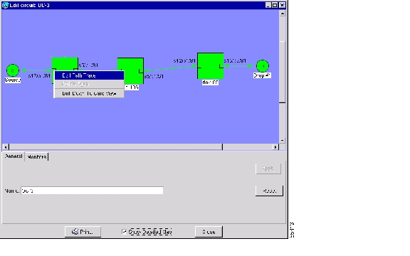
Figure 6-7 Selecting the Edit Path Trace option

Step 5 On the Circuit Path Trace window ( Figure 6-8) in the New Transmit String field (this field is available only on DS-1, DS3E, and DS3XM cards), enter the string that you want the source port to transmit. For example, you could enter the node IP address, node name, circuit name, or another string. If the New Transmit String field is left blank, the J1 transmits an empty string.

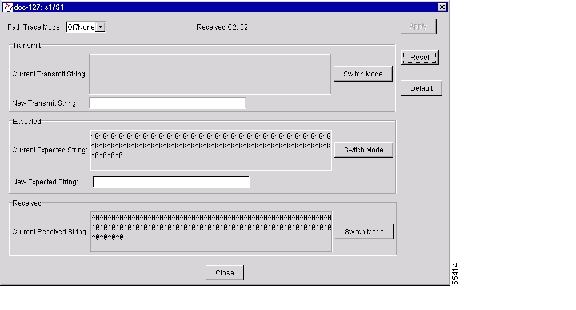
Figure 6-8 Setting up a path trace

Step 6 Click Apply but do not close the window.

Step 7 Return to the Edit Circuit window ( Figure 6-7).

Step 8 On the circuit map, right-click the drop port for the circuit and select Edit Path Trace from the shortcut menu.

Step 9 On the Circuit Path Trace window ( Figure 6-8) in the New Transmit String field (this field is available only on DS-1, DS3E, and DS3XM cards), enter the string that you want the drop port to transmit. If the field is left blank, the J1 transmits an empty string.

Step 10 If you will set Path Trace Mode to Manual in Step 11, enter the string that the drop port should expect to receive in the New Expected String field. This string must match the New Transmit String entered for the source port in Step 5. (When you click Apply in Step 12, this string becomes the Current Expected String.)

Step 11 In the Path Trace Mode field, select one of the following options:

Auto—Assumes the first string received from the source port is the baseline string. An alarm is raised when a string that differs from the baseline is received.

Manual—Uses the Current Expected String field as the baseline string. An alarm is raised when a string that differs from the Current Expected String is received.

Step 12 Click Apply and then click Close.

Step 13 Display the Circuit Path Trace window for the source port from Step 5.

Step 14 If you will set the Path Trace Mode to Manual in Step 15, enter the string the source port should expect to receive in the New Expected String field. This string must match the New Transmit String entered for the source port in Step 9.

Step 15 In the Path Trace Mode field, select one of the following options:

Auto—Assumes that the first string received from the drop port is the baseline string. An alarm is raised when a string that differs from the baseline is received.

Manual—Uses the Current Expected String field as the baseline string. An alarm is raised when a string that differs from the Current Expected String is received.

Step 16 Click Apply and click Close.

After you set up the path trace, the received string is displayed in the Received box on the path trace setup window ( Figure 6-8). Click Switch Mode to toggle between ASCII and hexadecimal display. Click the Reset button to reread values from the port. Click Default to return to the path trace default settings (Path Trace Mode is set to Off and the New Transmit and New Expected Strings are null).


6.8 Cross-Connect Card Capacities

The ONS 15454 XC, XCVT, and XC10G cards perform port-to-port time-division multiplexing (TDM).

XCs perform STS switching

XCVTs and XC10Gs perform STS and VT1.5 switching

XCs and XCVTs have capacity to terminate 288 STSs, or 144 STS cross-connections (each STS cross-connection uses two STS ports on the cross-connect card STS matrix). XC10Gs have capacity for 1152 STSs, or 576 STS cross-connections. Table 6-3 shows STS capacities for the XC, XCVT, and XC10G cards.


Note The Cisco ONS 15454 Troubleshooting and Maintenance Guide contains detailed specifications of the XC, XCVT, and XC10G cards.


Table 6-3 XC, XCVT, and XC10G Card STS Cross-Connect Capacities

Card
Total STSs
STS Cross-connects

XC

288

144

XCVT

288

144

XC10G

1152

576


6.8.1 VT1.5 Cross-Connects

XCVTs and XC10Gs can map up to 24 STSs for VT1.5 traffic. Because one STS can carry 28 VT1.5s, the XCVT and XC10G cards can terminate up to 672 VT1.5s, or 336 VT1.5 cross-connects. However, to terminate 336 VT1.5 cross-connects:

Each STS mapped for VT1.5 traffic must carry 28 VT1.5 circuits. If you assign each VT1.5 circuit to a different STS, the XCVT and XC10G VT1.5 cross-connect capacity will be reached after you create 12 VT1.5 circuits.

ONS 15454s must be in a bidirectional line switched ring (BLSR). Source and drop nodes in UPSR or 1+1 (linear) protection have capacity for only 224 VT1.5 cross-connects because an additional STS is used for the protect path.

Table 6-4 shows the VT1.5 capacities for ONS 15454 cross-connect cards. All capacities assume each VT1.5-mapped STS carries 28 VT1.5 circuits.

Table 6-4 XC, XCVT, and XC10G VT1.5 Capacities

Card
Total VT1.5s (BLSR)
VT1.5 Cross-Connect Capacity (BLSR)
VT1.5 Cross-Connect Capacity
(UPSR or 1+1)

XC

0

0

0

XCVT

672

336

224

XC10G

672

336

224


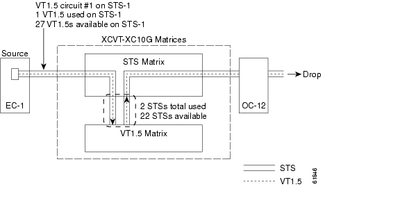
Figure 6-9 shows the logical flow of a VT1.5 circuit through the XCVT/XC10G STS and VT matrices at a BLSR node. The circuit source is an EC-1 card using STS-1. After the circuit is created:

Two of the 24 XCVT or XC10G STSs available for VT1.5 traffic are used (one STS for VT1.5 input into the VT matrix; one STS for VT1.5 output).

22 STSs are available for VT1.5 circuits.

The STS-1 from the EC-1 card has capacity for 27 more VT1.5 circuits.

Figure 6-9 Example #1: A VT1.5 circuit in a BLSR

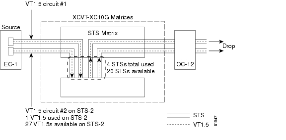
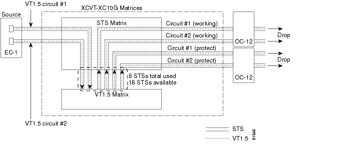
In Figure 6-10, a second VT1.5 circuit is created from the EC-1 card. In this example, the circuit is assigned to STS-2:

Two more of the 24 STSs available for VT1.5 traffic are used.

20 STSs are available on the XCVT or XC10G for VT1.5 circuits.

STS-2 can carry 27 additional VT1.5 circuits.

Figure 6-10 Example #2: Two VT1.5 circuits in a BLSR

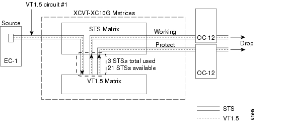
If you create VT1.5 circuits on nodes in UPSR or 1+1 protection, an additional STS is used for the protect path at the source and drop nodes. Figure 6-11 shows a VT1.5 circuit at a UPSR source node. When the circuit is completed:

Three of the 24 STSs available for VT1.5 mapping on the XCVT or XC10G are used (one input and two outputs, one output for the working path and one output for the protect path).

21 STSs are available for VT1.5 circuits.

Figure 6-11 Example #3: VT1.5 circuit in a UPSR or 1+1 protection scheme

Figure 6-12 shows a second VT1.5 circuit that was created using STS-2. When the second VT1.5 circuit is created:

Three more VT1.5-mapped STSs are used.

18 STSs are available on the XCVT or XC10G for VT1.5 circuits.

Figure 6-12 Example #4: Two VT1.5 circuits in UPSR or 1+1 protection scheme

Unless you create VT tunnels (see the "VT Tunnels" section), VT1.5 circuits use STSs on the XCVT/XC10G VT matrix at each node through which the circuit passes.

Two STSs are used at each node in the Figure 6-9 example, and three STSs are used at each node in the Figure 6-11 example.

In the Figure 6-10 example, three STSs are used at the source and drop nodes and four STSs are used at pass-through nodes. In Figure 6-12, six STSs are used at the source and drop nodes and four
STSs at the pass-through nodes.

6.8.2 VT Tunnels

To maximize VT matrix resources, you can tunnel VT1.5 circuits through ONS 15454 pass-through nodes (nodes that are not a circuit source or drop). VT1.5 tunnels provide two benefits:

They allow you to route VT1.5 circuits through ONS 15454s that have XC cards. (VT1.5 circuits require XCVT or XC10G cards at circuit source and drop nodes.)

When tunneled through nodes with XCVT or XC10G cards, VT1.5 tunnels do not use VT matrix capacity, thereby freeing the VT matrix resources for other VT1.5 circuits.

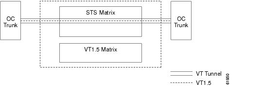
Figure 6-13 shows a VT tunnel through the XCVT and XC10G matrices. No VT1.5-mapped STSs are used by the tunnel, which can carry 28 VT1.5s. However, the tunnel does use two STS matrix ports on each node through which it passes.

Figure 6-13 A VT1.5 tunnel

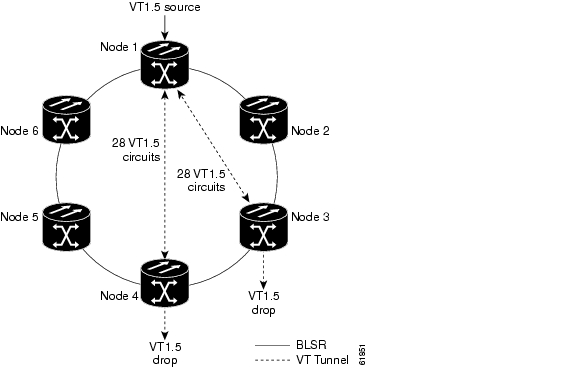
Figure 6-14 shows a six-node ONS 15454 ring with two VT tunnels. One tunnel carries VT1.5 circuits from Node 1 to Node 3. The second tunnel carries VT1.5 circuits from Node 1 to Node 4. Table 6-5 shows the VT1.5-mapped STS usage at each node in a ring based on protection scheme and use of VT tunnels. In the Figure 6-14 example, the circuit travels west through Nodes 2, 3, and 4. Subsequently, VT-mapped STS usage at these nodes is greater than at Nodes 5 and 6.

Figure 6-14 A six-node ring with two VT1.5 tunnels

Table 6-5 VT1.5-Mapped STS Use in Figure 6-6

Node
VT Tunnel (BLSR)
VT Tunnel (UPSR, 1+1)
No VT Tunnel (BLSR)
No VT Tunnel (UPSR)
No VT Tunnel (1+1)

1

4

6

4

6

6

2

0

0

4

3

8

3

2

3

4

3

6

4

2

3

2

3

3

5

0

0

0

2

0

6

0

0

0

2

0


When planning VT1.5 circuits, weigh the benefits of using tunnels with the need to maximize STS capacity. For example, a VT1.5 tunnel between Node 1 and Node 4 passing (transparently) through Nodes 2 and Node 3 is advantageous if a full STS is used for Node 1 - Node 4 VT1.5 traffic (that is, the number of VT1.5 circuits between these nodes is close to 28). A VT tunnel is required if:

Node 2 or Node 3 have XC cards, or

All VT1.5-mappable STSs at Node 2 and Node 3 are in use.

However, if the Node 1 - Node 4 tunnel will carry few VT1.5 circuits, creating a regular VT1.5 circuit between Nodes 1, 2, 3, and 4 might maximize STS capacity.

When you create a VT1.5 circuit, CTC determines whether a tunnel already exists between source and drop nodes. If a tunnel exists, CTC checks the tunnel capacity. If the capacity is sufficient, CTC routes the circuit on the existing tunnel. If a tunnel does not exist, or if an existing tunnel does not have sufficient capacity, CTC displays a dialog box asking whether you want to create a tunnel. Before you create the tunnel, review the existing tunnel availability, keeping in mind future bandwidth needs. In some cases, you may want to manually route a circuit rather than create a new tunnel.

6.9 Creating DCC Tunnels

SONET provides four data communications channels (DCCs) for network element operations, administration, maintenance, and provisioning: one on the SONET Section layer and three on the SONET Line layer. The ONS 15454 uses the Section DCC (SDCC) for ONS 15454 management and provisioning.

You can use the Line DCCs (LDCCs) and the SDCC (when the SDCC is not used for ONS 15454 DCC terminations) to tunnel third-party SONET equipment across ONS 15454 networks. A DCC tunnel end-point is defined by Slot, Port, and DCC, where DCC can be either the SDCC, Tunnel 1, Tunnel 2, or Tunnel 3 (LDCCs). You can link an SDCC to an LDCC (Tunnel 1, Tunnel 2, or Tunnel 3), and an LDCC to an SDCC. You can also link LDCCs to LDCCs and link SDCCs to SDCCs. To create a DCC tunnel, you connect the tunnel end points from one ONS 15454 optical port to another.

Each ONS 15454 can support up to 32 DCC tunnel connections. Table 6-6 shows the DCC tunnels that you can create.

Table 6-6 DCC Tunnels

DCC
SONET
Layer
SONET
Bytes
OC-3
(all ports)
OC-12, OC-48

SDCC

Section

D1 - D3

Yes

Yes

Tunnel 1

Line

D4 - D6

No

Yes

Tunnel 2

Line

D7 - D9

No

Yes

Tunnel 3

Line

D10 - D12

No

Yes


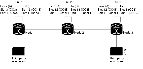
Figure 6-15 shows a DCC tunnel example. Third-party equipment is connected to OC-3 cards at Node 1/Slot 3/Port 1 and Node 3/Slot 3/Port 1. Each ONS 15454 node is connected by OC-48 trunk cards. In the example, three tunnel connections are created, one at Node 1 (OC-3 to OC-48), one at Node 2 (OC-48 to OC-48), and one at Node 3 (OC-48 to OC-3).

Figure 6-15 A DCC tunnel

When you create DCC tunnels, keep the following guidelines in mind:

Each ONS 15454 can have up to 32 DCC tunnel connections.

Each ONS 15454 can have up to 10 SDCC terminations.

An SDCC that is terminated cannot be used as a DCC tunnel end-point.

An SDCC that is used as an DCC tunnel end-point cannot be terminated.

All DCC tunnel connections are bidirectional.

Procedure: Provision a DCC Tunnel


Step 1 Log into an ONS 15454 that is connected to the non-ONS 15454 network.

Step 2 Click the Provisioning > Sonet DCC tabs.

Step 3 Beneath the DCC Tunnel Connections area (bottom right of the screen), click Create.

Step 4 In the Create DCC Tunnel Connection dialog box ( Figure 6-16), select the tunnel end points from the From (A) and To (B) lists.


Note You cannot use the SDCC listed under SDCC Terminations (left side of the window) for tunnel connections. These are used for ONS 15454 optical connections.


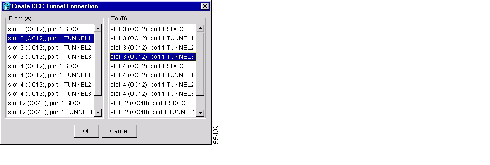
Figure 6-16 Selecting DCC tunnel end points

Step 5 Click OK.

Step 6 Put the ports hosting the DCC tunnel in service:

a. Double-click the card hosting the DCC in the shelf graphic or right-click the card on the shelf graphic and select Open.

b. Click the Provisioning > Line tabs.

c. Under Status, select In Service.

d. Click Apply.

DCC provisioning is now complete for one node. Repeat these steps for all slots/ports that are part of the DCC tunnel, including any intermediate nodes that will pass traffic from third party equipment. The procedure is confirmed when the third-party network elements successfully communicate over the newly-established DCC tunnel.


hometocprevnextglossaryfeedbacksearchhelp

Posted: Fri Feb 22 16:30:47 PST 2008
All contents are Copyright © 1992--2008 Cisco Systems, Inc. All rights reserved.
Important Notices and Privacy Statement.