|
|

Table Of Contents
3.2 Setting Up Basic Node Information
3.3 Setting Up Network Information
3.4 Creating Users and Setting Security
3.5 Creating Protection Groups
3.6 Setting Up ONS 15454 Timing
3.6.2 Synchronization Status Messaging
3.7 Viewing ONS 15454 Inventory
3.8 Viewing CTC Software Versions
Node Setup
This chapter explains how to set up a Cisco ONS 15454 node using the Cisco Transport Controller (CTC). Topics include:
•
Setting up general node information
•
•
•
•
•
•
•
Lastly, the chapter includes a node checklist to help you keep track of the procedures you have performed. See Chapter 2, "Software Installation" for general CTC information.
3.1 Before You Begin
Before you begin node setup, review the following checklist to ensure you have the perquisite information. Basic node information that you will provide need includes node name, contact, location, date, and time. If the ONS 15454 will be connected to a network, you will need:
•
•
•
If you are responsible for setting up IP networking for the ONS 15454 network, see Chapter 4, "IP Networking" for more information.
To create card protection groups, you will need to know:
•
•
Note
3.2 Setting Up Basic Node Information
Setting basic information for each Cisco ONS 15454 node is one of the first provisioning tasks you perform. This information includes node name, location, contact, and timing. Completing the information for each node facilitates ONS 15454 management, particularly when the node is connected to a large ONS 15454 network.
Procedure: Add the Node Name, Contact, Location, Date, and Time
Step 1
Step 2
Step 3
•
•
•
•
•
CTC uses the latitude and longitude to position node icons on the network view map. (You can also position nodes manually.) To convert a coordinate in degrees to degrees and minutes, multiply the number after the decimal by 60. For example, the latitude 38.250739 converts to 38 degrees, 15 minutes (.250739 x 60 = 15.0443, rounded to the nearest whole number).
•
•
•
•
Step 4
3.3 Setting Up Network Information
ONS 15454s almost always operate in network environments. Before you connect an ONS 15454 to other ONS 15454s or to a LAN, you must change the default IP address that is shipped with each ONS 15454 (192.1.0.2). IP addresses are unique identifiers for devices—called hosts—that connect to TCP/IP networks. Every IP address includes a network number, which is assigned to an organization, and a host (device) number, which the organization's LAN administrator assigns to an individual network device. Subnetting enables LAN administrators to create subnetworks that are transparent to the Internet. Within networks, ONS 15454s often exist as subnetworks, which are created by adding a subnet mask to the ONS 15454 IP address.
The following procedure tells you how to set up the essential ONS 15454 networking information. Additional ONS 15454 networking information and procedures, including IP addressing examples, static route scenarios and Open Shortest Path First (OSPF) protocol options are provided in Chapter 3, "IP Networking."
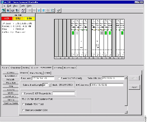
Procedure: Set Up Network Information
Step 1
Step 2
•
•
•
•
Note
•
•
Figure 3-1 Setting up general network information
Step 3
Step 4
Both ONS 15454 TCC+ cards will reboot, one at a time.
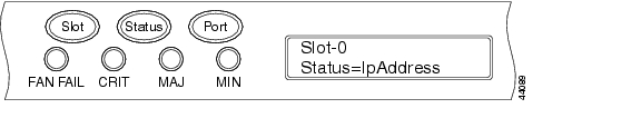
Procedure: Change IP Address, Default Router, and Network Mask Using the LCD
You can change the ONS 15454 IP address, subnet mask, and default router address using the Slot, Status, and Port buttons on the front panel LCD.
Note
Step 1
Step 2
•
•
•
Figure 3-2 Selecting the IP address option
Step 3
Figure 3-3 Changing the IP address
Step 4
Step 5
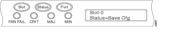
Step 6
Step 7
Figure 3-4 Selecting the Save Configuration option
Step 8
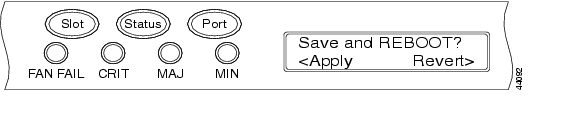
A Save and REBOOT message appears ( Figure 3-5).
Figure 3-5 Saving and rebooting the TCC+
Step 9
Saving the new configuration causes the TCC+ cards to reboot. During the reboot, a "Saving Changes - TCC Reset" message displays on the LCD. The LCD returns to the normal alternating display after the TCC+ reboot is complete.
3.4 Creating Users and Setting Security
The CISCO15 user provided with each ONS 15454 can be used to set up other ONS 15454 users. You can add up to 500 users to one ONS 15454. Each ONS 15454 user can be assigned one of the following security levels:
•
•
•
•
Table 3-1 shows the actions that each user can perform in node view.
Each ONS 15454 user has a specified amount of time that he or she can leave the system idle before the CTC window is locked. The lockouts prevent unauthorized users from making changes. Higher-level users have shorter idle times, as shown in Table 3-2.
Table 3-2 ONS 15454 User Idle Times
Superuser
15 minutes
Provisioning
30 minutes
Maintenance
60 minutes
Retrieve
Unlimited
You can perform ONS 15454 user management tasks from network or node view. In network view, you can add, edit, or delete users from multiple nodes at one time. If you perform user management tasks in node view, you can only add, edit, or delete users from that node.
Note
Procedure: Create New Users
Step 1
Step 2
Step 3
•
•
•
•
Step 4
Step 5
Procedure: Edit a User
Step 1
Step 2
Step 3
Note
Step 4
Step 5
Changed user permissions and access levels do not take effect until the user logs out of CTC and logs back in.
Procedure: Delete a User
Step 1
Step 2
Step 3
Step 4
Step 5
3.5 Creating Protection Groups
The ONS 15454 provides several card protection methods. When you set up protection for ONS 15454 cards, you must choose between maximum protection and maximum slot availability. The highest protection reduces the number of available card slots; the highest slot availability reduces the protection. Table 3-3 shows the protection types that can be set up for ONS 15454 cards.
Procedure: Create Protection Groups
Step 1
Step 2
Step 3
•
•
•
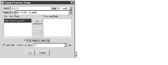
Based on these selections, a list of available working cards or ports is displayed under Available Cards or Available Ports. Figure 3-6 shows a 1+1 protection group.
Figure 3-6 Creating a 1+1 protection group
Step 4
Step 5
•
•
•
Step 6
Note
Card protection does not take effect until you enable the ports on all the cards in the protection group. Because ports must be enabled before the cards carry traffic, you can enable the ports immediately after provisioning card protection, or wait until you are ready to send traffic on the cards.
Caution
Procedure: Enable Ports
Step 1
Step 2
Step 3
Step 4
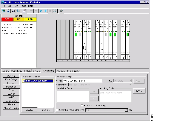
Procedure: Edit Protection Groups
Step 1
Figure 3-7 Editing protection groups
Step 2
Step 3
Step 4
Procedure: Delete Protection Groups
Step 1
Step 2
a.
b.
c.
Step 3
Step 4
Step 5
3.6 Setting Up ONS 15454 Timing
SONET timing parameters must be set for each ONS 15454. Each ONS 15454 independently accepts its timing reference from one of three sources:
•
•
•
You can set ONS 15454 timing to one of three modes: external, line, or mixed. If timing is coming from the BITS pins, set ONS 15454 timing to external. If the timing comes from an OC-N card, set the timing to line. In typical ONS 15454 networks:
•
•
You can set three timing references for each ONS 15454. The first two references are typically two BITS-level sources, or two line-level sources optically connected to a node with a BITS source. The third reference is the internal clock provided on every ONS 15454 TCC+ card. This clock is a Stratum 3 (ST3). If an ONS 15454 becomes isolated, timing is maintained at the ST3 level.
Caution
3.6.1 Network Timing Example
Figure 3-8 shows an ONS 15454 network timing setup example. Node 1 is set to external timing. Two timing references are set to BITS. These are Stratum 1 timing sources wired to the BITS input pins on the Node 1 backplane. The third reference is set to internal clock. The BITS output pins on the backplane of Node 3 are used to provide timing to outside equipment, such as a Digital Access Line Access Multiplexer.
In the example, Slots 5 and 6 contain the trunk cards. Timing at Nodes 2, 3, and 4 is set to line, and the timing references are set to the trunk cards based on distance from the BITS source. Reference 1 is set to the trunk card closest to the BITS source. At Node 2, Reference 1is Slot 5 because it is connected to Node 1. At Node 4, Reference 1 is set to Slot 6 because it is connected to Node 1. At Node 3, Reference 1 could be either trunk card because they are equal distance from Node 1.
Figure 3-8 An ONS 15454 timing example
3.6.2 Synchronization Status Messaging
Synchronization Status Messaging (SSM) is a SONET protocol that communicates information about the quality of the timing source. SSM messages are carried on the S1 byte of the SONET Line layer. They enable SONET devices to automatically select the highest quality timing reference and to avoid timing loops.
SSM messages are either Generation 1 or Generation 2. Generation 1 is the first and most widely deployed SSM message set. Generation 2 is a newer version. If you enable SSM for the ONS 15454, consult your timing reference documentation to determine which message set to use. Table 3-4 and Table 3-5 show the Generation 1 and Generation 2 message sets.
Procedure: Set up ONS 15454 Timing
Step 1
Step 2
•
•
•
•
•
Step 3
Note
•
•
•
•
•
Step 4
Note
•
–
–
–
•
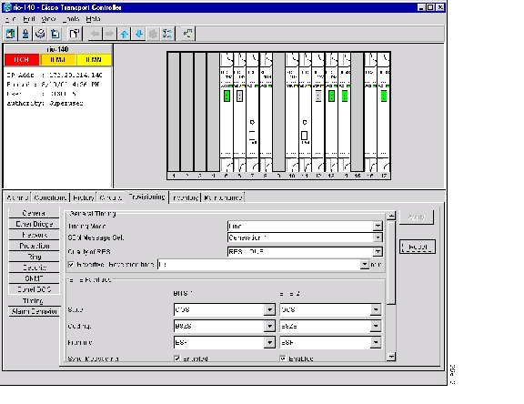
Figure 3-9 Setting Up ONS 15454 timing
Step 5
Note
Procedure: Set Up Internal Timing
If no BITS source is available, you can set up internal timing by timing all nodes in the ring from the internal clock of one node.
Caution
Step 1
Step 2
Step 3
•
•
•
•
•
Step 4
•
•
•
•
•
Step 5
•
–
–
–
•
Step 6
Step 7
Step 8
Step 9
•
Reference Lists
•
–
–
–
Step 10
Step 11
3.7 Viewing ONS 15454 Inventory
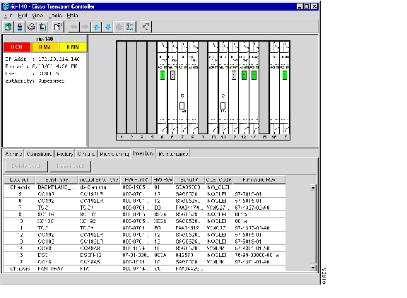
The Inventory tab ( Figure 3-10) displays information about cards installed in the ONS 15454 node including part numbers, serial numbers, hardware revisions, and equipment types. The tab provides a central location to obtain information and to determine applicability of ONS 15454 Product Change Notices (PCNs) and Field Service Bulletins (FSBs). Using the ONS 15454 export feature, you can export inventory data from ONS 15454 nodes into spreadsheet and database programs to consolidate ONS 15454 information for network inventory management and reporting.
Figure 3-10 Displaying ONS 15454 hardware information
The Inventory tab displays the following information about the cards installed in the ONS 15454:
•
•
•
Tip
•
•
•
•
•
3.8 Viewing CTC Software Versions
CTC software is pre-loaded on the ONS 15454 TCC+ cards; therefore, you do not need to install software on the TCC+. When a new CTC software version is released, you must follow procedures provided by the Cisco Technical Assistance Center (TAC) to upgrade the ONS 15454 software.
When you upgrade CTC software, the TCC+ stores the older CTC version as the protect CTC version, and the newer CTC release becomes the working version. You can view the software versions that are installed on an ONS 15454 by selecting the Maintenance tab followed by the Software subtab. Select these tabs in node view to display the software installed on one node. Select the tabs in network view to display the software versions installed on all the network nodes.
![]()
![]()
![]()
![]()
![]()
![]()
![]()
![]()
Posted: Fri Feb 22 16:19:58 PST 2008
All contents are Copyright © 1992--2008 Cisco Systems, Inc. All rights reserved.
Important Notices and Privacy Statement.