cc/td/doc/product/ong/15400/454docs
hometocprevnextglossaryfeedbacksearchhelp
PDF

Table Of Contents

Maintenance

10.1 Air Filter Inspection

10.1.1 Reusable Air Filter

10.1.2 Disposable Air Filter

10.2 System Reset

10.3 Database Backup and Restore

10.4 Revert To Earlier Software Load

10.5 Card Replacement

10.6 TCC Card to TCC+ Card Upgrade

10.7 Electrical Interface Assembly Replacement

10.7.1 EIA Types

10.7.2 Replacement Procedures

10.8 Fiber Cleaning


10

Maintenance


This chapter describes procedures needed to maintain the ONS 15454, including:

Air filter inspection

Hard and soft system resets

Card replacement

Database backup and restoration

Revert to earlier software load

Electrical Interface Assembly (EIAs) replacement

10.1 Air Filter Inspection

The Cisco ONS 15454 contains an air filter that should be removed and visually inspected approximately every 90 days, depending on the cleanliness of the operating environment. NEBS 3E and later versions of the ONS 15454 use a reusable air filter that is installed either beneath the fan tray assembly or in the optional external filter brackets. For more information on filter brackets, see the "Fan Tray Assembly" section on page 1-13. Earlier versions of the ONS 15454 use a disposable air filter that is installed beneath the fan tray assembly only. For more information on installing filters, see the "Fan Tray Assembly" section on page 1-13.

10.1.1 Reusable Air Filter

The reusable filter is made of a gray open cell polyurethane foam that is specially coated to provide fire and fungi resistance. NEBS 3E and later versions of the ONS 15454 use a reusable air filter. illustrates a reusable fan tray filter in an external filter bracket.

Figure 10-1 Reusable Fan Tray Filter in an External Filter Bracket

Procedure: Inspecting and Cleaning the Reusable Air Filter


Step 1 If the filter is installed in the external filter brackets, slide the filter out of the bracket while being careful not to dislodge any dust that may have collected on the filter. Proceed to Step 3. If the filter is not installed in the external filter brackets but under the fan tray, open the ONS 15454 door and fold out the retractable handles at each outside edge of the fan tray.

Step 2 Slide the fan tray out of the shelf by gently pulling the handles.

Step 3 Visually inspect the filter material for dirt and dust.

Step 4 If the reusable air filter contains a concentration of dirt and dust, either vacuum the filter or wash the filter under a faucet with a light detergent.


Note   If possible, cleaning should take place outside the operating environment to avoid releasing dirt and dust near the equipment.


Step 5 If you washed the filter, allow it to air dry.


Warning   Do not put a damp filter back in the ONS 15454.


Step 6 If the filter is installed in the external filter brackets, slide the filter all the way to the back of the bracket to complete the procedure.

Step 7 If the filter is not installed in the external filter brackets but under the fan tray, place the filter in the recessed compartment at the bottom of the ONS 15454 shelf assembly with the front edge of the filter flush against the front edge of the recessed compartment.

Step 8 Push the fan tray back into the shelf.


Caution   If the fan tray does not slide all the way to the back of the shelf assembly, pull the fan tray out and readjust the position of the reusable filter until the fan tray fits correctly.


Note   On a powered-up ONS 15454, the fans start immediately after the fan tray is correctly inserted.


Step 9 Rotate the retractable handles back into their compartments and close the ONS 15454 front door.


10.1.2 Disposable Air Filter

The disposable filter is made of spun white polyester that is flame retardant. This disposable filter is not designed to be cleaned. Versions of the ONS 15454 prior to the NEBS 3E version use a disposable air filter. You can order air filter replacements from Cisco (Cisco P/N 47-01-00001) or from Universal Air Filter as model PE-5 (Universal Air Filter Co., 1624 Sauget Ind. Parkway, Sauget, IL 62206.)


Note   You must remove the fan tray assembly to inspect and replace the disposable air filter.


Procedure: Inspecting and Replacing the Disposable Air Filter

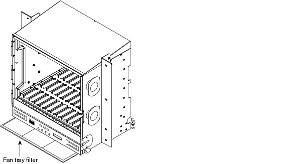
The fan tray assembly is located at the bottom of the front ONS 15454 compartment. The fan tray assembly is a removable drawer that holds fans and fan control circuitry for the ONS 15454. The fan tray has an electronic plug in the back. It must plug into a corresponding receptacle on the shelf assembly backplane.


Note   After you route cables in the tray, make sure the tray can swing forward on its hinges without disrupting cable routing. A hinged panel protects the cable management tray.


Step 1 Remove the front door of the shelf assembly.

Step 2 Open the front covers of the fiber management area.

Step 3 Lower the hinged panels in front of the cable management tray.

Step 4 Slide the fan tray out of the shelf (see Figure 10-2).

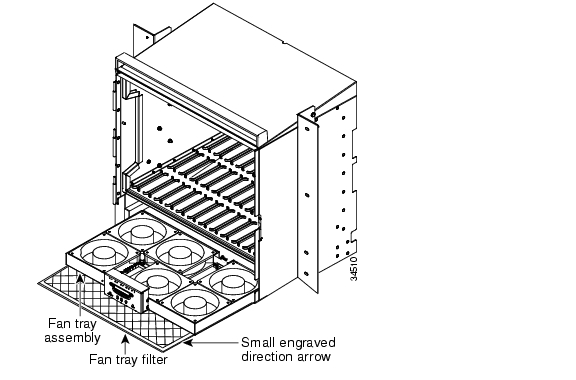
Figure 10-2 Fan Tray Assembly

Step 5 Carefully slide the air filter out of the shelf assembly (see ). Be careful not to dislodge any dust that may have collected on the filter.

Step 6 Visually inspect the white filter material for dirt and dust.

Step 7 If the air filter shows a heavy concentration of dirt and dust, replace it with a new filter.

Step 8 To be sure you are installing the fan tray assembly correctly, make sure the air flow indications on the filter point upwards.

Step 9 Slide the filter into the bottom of the shelf assembly, making sure that the front of the filter is flush with the front of the shelf assembly.

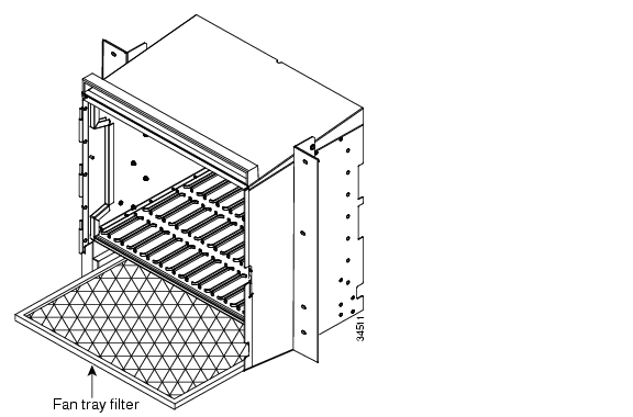
Figure 10-3 Air Filter

Step 10 Slide the fan tray into the shelf until the electrical plug at the rear of the tray plugs into the corresponding receptacle on the backplane of the shelf unit.

Step 11 To verify that the tray is plugged into the backplane, ensure that the LCD on the front of the fan tray is activated.

Step 12 Close the cable management tray.

Step 13 Raise the hinged panel at the front of the cable management tray.

Step 14 Close the front covers of the fiber management area.

Step 15 Replace the front door of the shelf assembly.


10.2 System Reset

The ONS 15454 TCC/TCC+ may be reset using the Cisco Transport Controller (CTC) (a soft reset) or by physically reseating a TCC/TCC+ card (a hard reset). A soft reset reloads the operating system, and application software and reboots the TCC/TCC+. A hard reset also temporarily removes power from the TCC/TCC+ and clears all buffer memory.

A soft reset can be applied to either an active or standby TCC/TCC+ without affecting traffic. A hard reset should only be applied to a standby TCC/TCC+. If you need to perform a hard reset on an active TCC/TCC+, put the TCC/TCC+ into standby mode first by performing a soft reset on the card.

Procedure: Performing a Soft Reset


Step 1 Go to the node level view of the CTC.

Step 2 Right click on the TCC/TCC+ card to reveal a pull-down menu.

Step 3 Click Reset Card (see ).

Step 4 Click YES when the "Are You Sure?" dialog appears.

Step 5 Click OK when the "Lost connection to node, changing to Network View" dialog appears.

Step 6 Confirm that the TCC comes back up in standby mode after the reset.

Figure 10-4 Soft Reset


Procedure: Performing a Hard Reset


Note   To determine whether you have an active or standby TCC/TCC+, position the cursor over the TCC/TCC+ card graphic to display the status.


Step 1 If you need to perform a hard reset on an active TCC/TCC+ card, first perform a soft reset on the active TCC/TCC+ (see the "Performing a Soft Reset" section).

Step 2 When the TCC /TCC+ is in standby mode, unlatch both the top and bottom ejector levers on the TCC/TCC+ card.

Step 3 Physically pull the card at least partly out of the slot until the lighted LEDs turn off.

Step 4 Wait 30 seconds. Reinsert the card and close the ejector levers.


Note   The TCC/TCC+ will take several minutes to reboot and will display the yellow standby LED after rebooting.


10.3 Database Backup and Restore

When dual TCC/TCC+ cards are installed in the ONS 15454, each TCC/TCC+ card hosts a separate database, therefore, the protect card's database is available if the database on the working TCC/TCC+ fails. A user can also store a back-up of the database on the workstation running the CTC. This operation should be part of a regular ONS 15454 maintenance program at approximately weekly intervals, and should also be completed when preparing an ONS 15454 for a pending natural disaster, such as a flood or fire.


Caution   If you are restoring the database on multiple nodes, wait five minutes between each database restore.


Caution   IE1000-2 cards lose traffic for approximately 30 seconds when a database is restored. Traffic is lost during this period while the spanning tree reconverges. The CARLOSS alarm will appear and clear during this period.

Procedure: Backup the Database


Step 1 Log into the CTC.

Step 2 Click the Maintenance tab and the Database subtab.

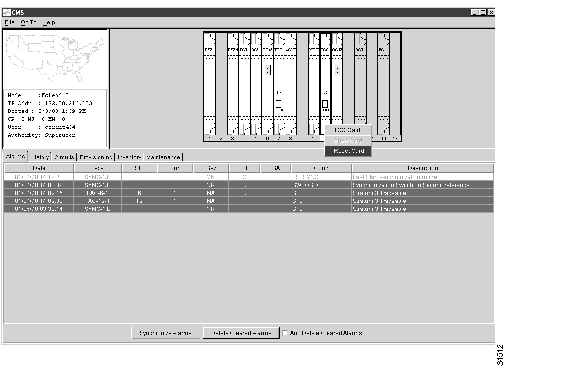
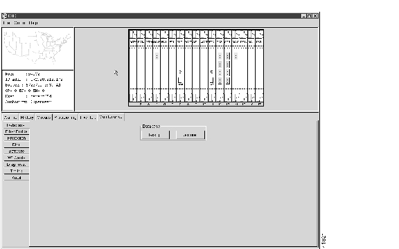
Figure 10-5 Database Backup Screen

Step 3 Click Backup.

Step 4 Save the database on the workstation's hard drive or on network storage. Use an appropriate file name with the file extension .db, for example, database.db.

Step 5 Click Save.

Figure 10-6 File Received Dialog

Step 6 Click OK on the File Received dialog.


Procedure: Restoring the Database


Step 1 Log into the CTC.

Step 2 Click the Maintenance tab and the Database subtab.

Figure 10-7 Database Backup Screen

Step 3 Click Restore.

Step 4 Locate the database file stored on the workstation's hard drive or on network storage.

Step 5 Click the database file to highlight it.

Step 6 Click Open.

Figure 10-8 File Transfer Dialog

Step 7 Wait for the selected file to complete the transfer to the TCC.

Step 8 Click OK on the File Transfer dialog to reboot the TCC and load the recovered database file.


10.4 Revert To Earlier Software Load

Prior to Release 2.2.1, the ONS 15454 could not revert to an earlier software database without deleting the current database and losing both cross-connect and DCC connectivity. This would result in a loss of traffic until the user manually restored the previous database or recreated the existing circuits.

Revert allows the system to switch to another software load and its attendant database without affecting traffic or DCC connectivity. This feature requires dual TCC+ cards and CTC software Release 2.2.1.

When you click the Activate button after a software upgrade, the TCC+ copies the current working database and saves it in a reserved location in the TCC+ flash memory. If later a user needs to switch back to the original working software load from the protect software load, the saved database installs automatically. The user does not need to restore the database manually or recreate circuits, and traffic runs without disruption.

The revert feature is useful when a maintenance window closes on a user upgrading CTC software. The user can revert to the standby software load without losing traffic. When the next maintenance window opens, the user completes the upgrade and activates the new software load.


Note   Circuits created after clicking the Activate button will not reinstate with a revert. Only changes made prior to clicking the Activate button will be saved and reinstated.


Procedure: Revert To Earlier Software Load


Step 1 Log into the CTC.

Step 2 Record the IP address of that node.

Step 3 Go to the node view of the CTC.

Step 4 Right click on the standby TCC+ card to reveal a pull-down menu.

Step 5 Click Reset Card.

Step 6 Click YES when the "Are You Sure?" dialog appears.

Step 7 Click OK when the "Lost connection to node, changing to Network View" dialog appears.

Step 8 Confirm that the TCC+ comes back up in standby mode after the reset.

Step 9 Click the Maintenance tab and the Software tab.

Step 10 Verify that the protect software is Version 2.2.0 or later.

Step 11 Click Revert.

The Revert button activates the protect software load. The ONS node will reboot and lose the connection to the CTC.

Step 12 Wait until the software upgrade finishes. This may take as long as 30 minutes.

Step 13 Completely close the browser.

Step 14 Restart the browser and log back into the node using the IP address recorded in Step 2.

The browser downloads the CTC applet for the standby software load.


10.5 Card Replacement

To replace an ONS 15454 card with another card of the same type, you do not need to make any changes to the database; remove the old card and replace it with a new card.

To replace a card with a card of a different type, the database must be updated to reflect the change. After physically removing the card and replacing it with the new card, delete the original card from CTC and add the replacement card to CTC using the provisioning commands. See "," for instructions.

To upgrade a TCC card to a TCC+ card, see the "TCC Card to TCC+ Card Upgrade" section. To upgrade an XC card to an XCVT card, see the "Upgrading XC Cards to XCVT" section.

10.6 TCC Card to TCC+ Card Upgrade


Caution   An ONS 15454 must operate with a matching pair of either TCC cards or TCC+ cards.


Caution   The TCC card supports ONS 15454 Release 2.2 and earlier software versions. The TCC+ card supports ONS 15454 Release 2.2 and later software versions.

Verify that the ONS 15454 is running Release 2.2 software before starting the upgrade procedure. The TCC to TCC+ upgrade process requires Release 2.2 to support the TCC/TCC+ mismatch that occurs briefly during the TCC to TCC+ upgrade process.

The ACT/STBY LED on the faceplate of the TCC/TCC+ card indicates whether the card is in active or standby mode. A green ACT/STBY LED indicates an active card and an amber light indicates a card in standby. See the "Timing Communication and Control (TCC/TCC+) Card" section on page 2-7 for more information about the TCC/TCC+ card.

Procedure: Upgrade the TCC Card to the TCC+ Card


Step 1 Physically replace the standby TCC card on the ONS 15454 with a TCC+ card.

(a) Open the TCC card ejectors.

(b) Slide the card out of the slot.

(c) Open the ejectors on the TCC+ card.

(d) Slide the TCC+ card into the slot along the guide rails.

(e) Close the ejectors.


Note   The MEA (card mismatch) alarm appears because the CTC recognizes a mismatch between TCC card types. Disregard this alarm; it clears by the end of the procedure.


Caution   It takes approximately 20 minutes for the active TCC to transfer the system software to the newly installed TCC+. Software transfer occurs in instances where different software versions exist on the two cards. During this operation, the LEDs on the TCC+ flash Fail and then the Active/Standby LED flashes. When the transfer completes, the TCC+ reboots and goes into Standby mode after approximately three minutes.

Step 2 Right click the active TCC card to reveal a pull-down menu.

Step 3 Click Reset Card (see ).

Figure 10-9 Soft Reset

Wait for the TCC to reboot. The ONS 15454 switches the standby TCC+ card to active mode.

Step 4 Verify that the remaining TCC card is now in standby mode (the ACT/STBY LED changes to amber).

Step 5 Physically replace the remaining TCC card with the second TCC+ card.

(a) Open the TCC card ejectors.

(b) Slide the card out of the slot.

(c) Open the ejectors on the TCC+ card.

(d) Slide the TCC+ card into the slot along the guide rails.

(e) Close the ejectors.

The ONS 15454 boots up the second TCC+ card. The second TCC+ must also copy the system software, which may take up to twenty minutes. The MEA alarm clears when the ONS 15454 recognizes the matching TCC+s.


10.7 Electrical Interface Assembly Replacement

Electrical Interface Assemblies (EIAs) provide cable connection points on the back of the ONS 15454 and come in several configurations that work with different cards and connections (see ). For more information on EIAs, see the "Backplane Covers" section on page 1-18.

EIAs have two sides. As you face the rear of the ONS 15454 shelf assembly, the right-hand side is the A side and the left-hand side is the B side. EIAs install on one or both sides of the ONS 15454 backplane in any combination. For example, you can use an AMP CHAMP EIA on side A and a BNC EIA on side B. EIAs come pre-installed on the ONS 15454 when ordered with the system.

10.7.1 EIA Types

gives the product numbers and common names for EIAs.

Table 10-1 EIA Configurations

EIA Type
Cards Supported
Side A Hosts
A Side Columns Map to
A Side Product Number
Side B Hosts
B Side Columns Map to
B Side Product Number

BNC

DS-3 DS3XM-6 EC-1

24 pairs of BNC connectors

Slot 2

Slot 4

15454-EIA-BNC-A24

24 pairs of BNC connectors

Slot 14

Slot 16

15454-EIA-BNC-B24

High Density BNC

DS-3 DS3XM-6 EC-1

48 pairs of BNC connectors

Slot 1

Slot 2

Slot 4

Slot 5

15454-EIA-BNC-A48

24 pairs of BNC connectors

Slot 13

Slot 14

Slot 16

Slot 17

15454-EIA-BNC-B48

SMB

DS-1

DS-3

EC-1

DS3XM-6

84 pairs of SMB connectors

Slot 1

Slot 2

Slot 3

Slot 4

Slot 5

Slot 6

15454-EIA-SMB-A84

84 pairs of SMB connectors

Slot 12

Slot 13

Slot 14

Slot 15

Slot 16

Slot 17

15454-EIA-SMB-B84

AMP CHAMP

DS-1

6 AMP CHAMP

connectors

Slot 1

Slot 2

Slot 3

Slot 4

Slot 5

Slot 6

15454-EIA-AMP-A84

6 AMP CHAMP

connectors

Slot 12

Slot 13

Slot 14

Slot 15

Slot 16

Slot 17

15454-EIA-AMP-B84


Note   The top of the EIA connector columns are labelled with the corresponding slot number.


Note   EIA connector pairs are marked Tx and Rx to correspond to transmit and receive cables.


Note   SMB EIAs support 14 ports per slot when used with a DS-1 card, 12 ports per slot when used with a DS-3 or EC-1 card, and 6 ports per slot when used with a DS3XM-6.


10.7.2 Replacement Procedures

The replacement procedure is the same for all the EIA types. However, installing the AMP CHAMP EIA requires the additional step of attaching the fastening plate to the bottom of the connector row. Before you attach a new EIA, you must remove the backplane cover or EIA already attached to the ONS 15454.

Procedure: Remove the Backplane Cover or EIA


Step 1 To remove the lower backplane cover, loosen the five screws that secure it to the ONS 15454 and pulling the backplane away from the shelf assembly.

Step 2 Loosen the nine perimeter screws that hold the backplane sheet metal cover in place.


Note   Do not remove the interior screws.


Note   If you are removing an AMP CHAMP EIA, remove the fastening plate before proceeding. To remove the fastening plate, loosen the two thumbscrews.


Step 3 If a backplane cover is attached to the ONS 15454, lift the panel by the bottom to remove it from the shelf assembly and store the panel for later use.

Step 4 If an EIA is attached to the ONS 15454, lift the EIA handles and gently pull the EIA panel away from the backplane.


Note   Attach backplane sheet metal cover(s) whenever EIA(s) are not installed.


Procedure: Install the BNC EIAs


Step 1 Line up the connectors on the EIA with the mating connectors on the backplane.

Step 2 Gently push the EIA until both sets of connectors fit together snugly.

Step 3 Replace the nine perimeter screws that you removed while removing the backplane cover.

Step 4 If you are installing an AMP CHAMP EIA, attach the fastening plate with the two thumbscrews.

Step 5 Reattach the lower backplane cover.


Due to the large number of BNC connectors on the High-density BNC EIA, you might require a special tool for BNC insertion and removal (see Figure 10-10). This tool also helps with ONS 15454 patch panel connections.

Figure 10-10 BNC Insertion and Removal Tool

This tool can be obtained with P/N 227-T1000 from:

Amphenol USA (www.amphenol.com)

One Kennedy Drive

Danbury, CT 06810

Phone: 203-743-9272 Fax: 203-796-2032

This tool can be obtained with P/N RT-1L from:

Trompeter Electronics Inc. (www.trompeter.com)

31186 La Baya Drive

Westlake Village, CA 91362-4047

Phone: (800) 982-2629 Fax: (818) 706-1040

10.8 Fiber Cleaning

No special instructions apply to cleaning a fiber connected to an ONS node. Clean the fiber according to local site practice. If no local practice exists, use a CLETOP Real-Type or equivalent fiber optic cleaner and follow the instructions accompanying the product.


hometocprevnextglossaryfeedbacksearchhelp

Posted: Mon Feb 25 07:41:27 PST 2008
All contents are Copyright © 1992--2008 Cisco Systems, Inc. All rights reserved.
Important Notices and Privacy Statement.