cc/td/doc/product/ong/15400/454docs
hometocprevnextglossaryfeedbacksearchhelp
PDF

Table Of Contents

Provisioning Cards

5.1 Provisioning Electrical Cards

5.1.1 Card Settings

5.1.2 Provisioning DS3XM-6 Cards

5.2 Provisioning Optical Cards

5.3 Provisioning the OC-3 Card for STM-1

5.4 Provisioning the Alarm Interface Controller

5.4.1 Using Virtual Wires

5.4.2 Provisioning AIC Orderwire

5.4.3 Using the AIC Orderwire

5.5 Converting DS-1 and DS-3 Cards From 1:1 to 1:N Protection

5.6 Upgrading XC Cards to XCVT


5

Provisioning Cards


This chapter provides procedures to configure ONS 15454 electrical cards, optical cards, and the Alarm Interface Controller card. The chapter also tells you how to upgrade the XC card to an XCVT card and convert the DS1-14 and DS3-12 cards from 1:1 to 1:N protection.

5.1 Provisioning Electrical Cards

The DS1-14, DS1N-14, DS3-12, DS3N-12, DS3XM-6, and EC1-12 cards are pre-provisioned with settings that you can modify to manage transmission quality. To provision electrical card settings, open the card in CTC and select the Provisioning tab. Use the subtabs to provision the line, line threshold, line electrical path, and SONET thresholds.

5.1.1 Card Settings

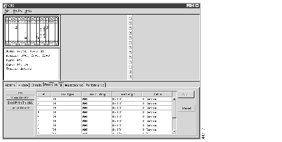
The Line subtab is where you set transmission line settings, including line type, coding, length, and status. shows the Line subtab for the DS1-14 card. shows the available electrical card line settings.

Figure 5-1 Line Subtab

Table 5-1 Line Settings - Electrical 

Heading
Description
Options

#

Port number

1 - 6 (DS3XM-6)

1 - 12 (DS3-12, DS3N-12, EC1-12)

1 - 14 (DS1-14, DS1N-14)

Line Type

Defines the line framing type

D4 (default)

ESF - Extended Super Frame

Unframed

M13 - DS3XM-6 only

C BIT - DS3XM-6 only; default

Line Coding

Defines the DS-1 transmission coding type that is used

AMI - Alternate Mark Inversion (default)

B8ZS - Bipolar 8 Zero Substitution

B3ZS - DS3XM-6 only, default

Line Length

Defines the distance (in feet) from backplane connection to the next termination point

DS-1:

0 - 131 (default)

132 - 262

263 - 393

394 - 524

525 - 655

DS-3. DS3XM-6

0 - 225 (default)

226 - 450

Status

Places port in or out of service

Out of Service (default)

In Service

PJ Sts Mon #

(EC1-12 only)

Sets the STS that will be used for pointer justification. If set to zero, no STS is used

0 (default)

1

Line Buildout

(EC1-12 only)

Defines the distance (in feet) from backplane to next termination point

0 - 225 (default)

226 - 450

Rx Equalization (EC1-12 only)

For early EC1-12 card versions, equalization can be turned off if the line length is short or the environment is extremely cold; Rx Equalization should normally be set to On

On (checked, default)

Off (unchecked)


shows electrical card threshold settings for all ONS 15454 electrical cards except the DS3XM-6. shows the DS3XM-6 card thresholds. The default values are based on threshold recommendations in GR-820-CORE, Sections 4.0 (DS-1) and 5.0 (DS-3).

Table 5-2 Threshold Settings - Electrical 

Heading
Description
Options

#

Port number

1 - 12 (DS3-12, DS3N-12, EC1-12)

1 - 14 (DS1-14, DS1N-14)

CV

Coding violations

Numeric. Defaults (15 min/1 day):

13,340/133,400 (DS-1)

387/3,865 (DS-3)

1,312/13,120 (EC-1)

ES

Errored Seconds

Numeric. Defaults (15 min/1 day):

65/648 (DS-1)

25/250 (DS-3)

87/864 (EC-1)

SES

Severely Errored Seconds

Numeric. Defaults (15 min/1 day):

10/100 (DS-1)

4/40 (DS-3)

1/4 (EC-1)

SAS

Severely Errored Frame/Alarm Indication Signal

Numeric. Default (15 min/1 day):

2/17 (DS-1)

UAS

Unavailable Seconds

Numeric. Default (15 min/1 day):

3/10 (all cards)

AIS

Alarm Indication Signal

Numeric. Default (15 min/1 day):

10/10 (DS-1)

Loss

Loss of signal

Numeric. Default (15 min/1 day):

10/10 (DS-3)

PJ

Pointer Justification

Numeric. Defaults (15 min/1 day):

60/5,760 (EC-1 Near End)

0/0 (EC-1 Far End)

SEFS

Severely errored frame seconds

Numeric. Defaults (15min/1 day):

500/5,000 (EC-1 Near End)

0/0 (EC-1 Far End)

SF BER Level

Sets the signal fail bit error rate

EC-1 card only:

1E-3

1E-4 (default)

1E-5

SD BER Level

Sets the signal degrade bit error rate

EC-1 card only:

1E-5

1E-6

1E-7 (default)

1E-8

1E-9


Table 5-3 Threshold Settings - DS3XM-6 Card 

Heading
Description
Options

#

Port number

1 - 6

CV

Coding violations

Numeric. Defaults (15 min/1 day):

387/3,865 (Line)

382/3,820 (Electrical Path - DS-3, Near and Far End))

ES

Errored Seconds

Numeric. Defaults (15 min/1 day):

25/250 (Line)

25/250 (Electrical Path - DS-3, Near & Far End)

65/648 (Electrical Path - DS-1 Near End)

0/0 (Electrical Path - DS-1, Far end)

SES

Severely Errored Seconds

Numeric. Defaults (15 min/1 day):

4/40 (Line)

4/40 (Electrical Path - DS-3, Near and Far End)

10/100 (Electrical Path - DS-1 Near End)

0/0 (Electrical Path - DS-1, Far end)

SAS

Severely Errored Frame/Alarm indication Signal

Numeric. Defaults (15 min/1 day):

2/8 (Electrical Path - DS-3, Near & Far End)

2/17 (Electrical Path - DS-1 Near End)

0/0 (Electrical Path - DS-1, Far end)

UAS

Unavailable Seconds

Numeric. Defaults (15 min/1 day):

10/10 Electrical Path, DS-1, Near End; DS-3; Near & Far End

0/0 Electrical Path, DS-1 Far End

AIS

Alarm Indication Signal

Numeric. Defaults (15 min/1 day):

10/10 Electrical Path, DS-1, Near End; DS-3; Near & Far End

0/0 Electrical Path, DS-1 Far End

Loss

Loss of signal

Numeric. Default (15 min/1 day):

10/10 (Line)


5.1.2 Provisioning DS3XM-6 Cards

The DS3XM-6 transmux card can accept up to six DS-3 signals and convert each to 28 VT1.5s. Conversely, it can take 28 T-1s and multiplex them into a channeled CBIT or M23 framed DS-3. Unlike the DS3-12 and DS3N-12 cards, the DS3XM-6 allows circuit mapping at the VT level. To provision a DS3XM-6 card, perform three basic steps:

Set up the protection groups

Set up the circuits

Provision the ports

Procedure: Set Up DS3XM-6 Protection Groups


Step 1 Click the Provisioning>Protection tabs.

Step 2 Click Create.

Step 3 In the Create Protection Group dialog, type the name for the protection group in the Name field (optional).

Step 4 Click Type and choose 1:1 from the pull-down menu. (1:1 is the only type of protection available for the DS3XM-6 card.)


Note   For 1:1 protection groups, install the protect card in an odd-numbered slot and the working card in an even-numbered slot that follows the protect slot.


Step 5 Click Protect Card and select the protect card from the pull-down menu.

The selected card will appear in the Protect Card field.

Step 6 To select the working card, click the card and click the arrow tab (>>) to move the card from the Available side to the Working side.

Step 7 Click OK.


After you set up the protection groups for the DS3XM-6 card, set up the circuits. For circuit provisioning procedures, see the "Creating and Provisioning Circuits" section. Setting up circuits for the DS3XM-6 is identical to other cards.

Procedure: Provision the DS3XM-6 Ports


Step 1 To open the DS3XM-6 card, either double click or right click the card and choose Open from the list of options.

Step 2 Click the Provisioning tab.

Step 3 In the Line subtab, ( Figure 5-2) complete the following fields:

Line Type—set framing (either M23 or C BIT)

Line coding—always set to B3ZS

Line Length—set the line length from your equipment to a patch panel. Line length is the same as line build out (LBO).

Status—choose In Service from the pull-down menu.

Step 4 Click Apply.

Step 5 Select the Line Thrshld, Sonet Thrshld, and Elect Path Thrshld subtabs to set the card's performance monitoring thresholds.

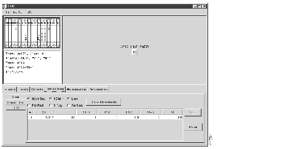
Figure 5-2 Port Provisioning (DS3XM-6 Card)


The DS3XM-6 card is now provisioned. Refer to this section whenever you need to install a new DS3XM-6 card.

5.2 Provisioning Optical Cards

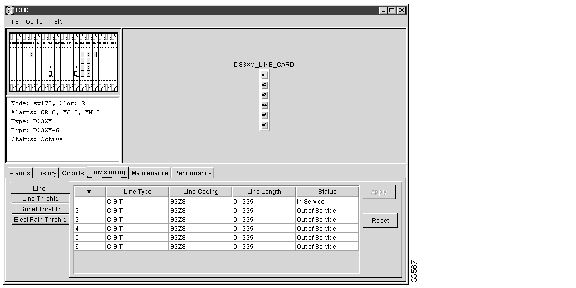
The OC-3, OC-12, and OC-48 cards are pre-provisioned with settings that you can modify to manage transmission quality. To provision the optical cards, open the card in CTC and select the Provisioning tab. Each optical card provides three subtabs: Line, Thresholds, and STS. shows the Thresholds subtab for an OC12 IR 1310 card.

Figure 5-3 Thresholds Subtab - OC12 IR 1310 Card

The Line subtab provisions line transmission quality settings. Line settings are shown in .

Table 5-4 Line Settings - Optical 

Heading
Description
Options

#

Port number

1 (OC-12, OC-48)

1-4 (OC-3)

SF Ber Level

Sets the signal fail bit error rate

1E-3

1E-4 (default)

1E-5

SD Ber Level

Sets the signal degrade bit error rate

1E-5

1E-6

1E-7 (default)

1E-8

1E-9

Provides Synch

If checked, the card is provisioned as a network element timing reference on CTC Provisioning>Timing tabs

Read-only

Yes (checked)

No (unchecked)

Enable Synch Messages

Enables synchronization status messages (S1 byte), which allows the node to choose the best clocking source

Yes (checked, default)

No (unchecked)

Send Do Not Use

When checked, sends a DUS (do not use) message on the S1 byte

Yes (checked)

No (unchecked; default)

PJ Sts Mon #

Sets the STS that will be used for pointer justification. If set to 0, no STS is monitored. (Only one STS per card can be monitored, even on a multiport card such as the OC-3)

0 (default) - 3 (OC-3, per port)

0 (default) - 12 (OC-12)

0 (default) - 48 (OC-48)


shows the ONS 15454 optical threshold settings.

Table 5-5 Threshold Settings - Optical

Heading
Description
Options

#

Port number

1 (OC-12, OC-48)

1-4 (OC-3)

CV

Coding violations (Line)

Numeric. Defaults (15 min/1 day):

1312/13,120 (OC-3 Near and Far End))

5,315/53,150 (OC-12 Near and Far End)

21,260/212,600 (OC-48 Near & Far End)

ES

Errored Seconds (Line)

Numeric. Default (15 min/1 day):

87/864 (Near and Far End)

SES

Severely Errored Seconds (Line)

Numeric. Defaults (15 min/1 day)

1/4 (Near and Far End)

PSC

Protection Switching Count (Line)

Numeric. Default (15 min/1 day):

1/5 (Near End)

0/0 (Far End)

PSD

Protection Switch Duration (Line)

Numeric. Default (15 min/1 day):

300/600 (Near End)

0/0 (all optical cards, Far End

UAS

Unavailable Seconds (Line)

Numeric. Default (15 min/1 day):

3/10 (Near and Far End)

PJ

Pointer Justification (Path)

Numeric. Default:

60/5,760 (Near End)

0/0 (Far End)

SEFS

Severely errored frame seconds

Numeric. Default:

500/5,000 (Near End)

0/0 (Far End)


5.3 Provisioning the OC-3 Card for STM-1

You can provision the OC3 IR 4 1310 card to support either OC-3 or STM-1 signals. When provisioned for STM-1, all four ports drop and insert STM-1 traffic in unprotected or 1+1 protected Automatic Protection Switching (APS) mode. Each STM-1 signal is mapped as a 155 Mbps concatenated signal (STS-3c) for transparent transport over a SONET network. The original STM-1 traffic may be handed off as an STM-1 or OC-3.

Because SDH and SONET frame format and size are nearly identical, their line speed meets, starting at 155 Mbps. At the STM-1/OC-3 level, the ONS 15454 performs section and line overhead conversions and maps the 261x9 byte VC-4 into an STS-3c for transparent transport across the SONET domain. At the far end, the STS-3c carrying the original VC-4 is then remapped into an STM-1 for handoff to an SDH network element.

The ONS 15454 performs section, line overheads and pointer conversions between SDH and SONET for an STM-1 to OC-3c circuit. However, to ensure operability, the following requirements must be met:

The embedded payload must be compatible on both sides and require no conversion of any kind. Examples of such payloads include concatenated ATM or Packet over SONET/SDH signals.

The path overhead (POH) must be compatible on both sides and require no conversion of any kind. Each overhead byte must be processed identically or simultaneously ignored. Key POH bytes to consider are the J1 (path indicator) and C2 (payload format).

Most SONET and SDH routers and ATM switches can be configured to meet these requirements.

Procedure: Provision the OC3 IR 4 1310 for STM-1


Step 1 Log into the node and double click the OC3 IR 4 1310 card.

Step 2 Click the Provisioning>Line tabs.

Step 3 Under Line Mode (bottom of window), choose SDH.

Step 4 Click Apply.


5.4 Provisioning the Alarm Interface Controller

The Alarm Interface Controller (AIC) card can be provisioned to receive input from, or send output to, external devices wired to the ONS 15454 backplane. (For a description of the AIC, see the "Alarm Interface Controller Card" section on page 2-19.) You can provision the AIC to:

Generate CTC alarms based on events detected by external devices such as heating or cooling equipment failure, fire alarms, smoke detection, and other environmental changes that can damage ONS 15454 equipment.

Turn external devices on or off based on a CTC alarm. For example, you can provision the AIC to turn on an audio or visual device, such as a bell or light, when a critical ONS 15454 alarm occurs.

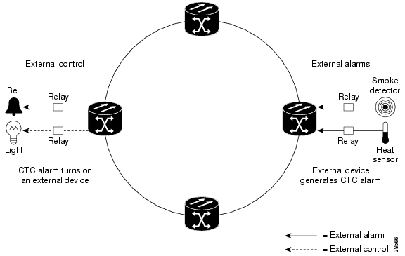
shows the flow to and from external devices provisioned through the AIC.

Figure 5-4 AIC Alarm Input and Output

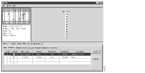
To provision the AIC, open the card in CTC and select the Provisioning tab ( ). You provision external alarms using the External Alarms subtab and provision external controls using the External Controls subtab.

Figure 5-5 AIC Provisioning Tab - External Alarms Subtab

External devices provisioned on the AIC are wired to the Environmental Alarms (ENVIR ALARMS IN and ENVIR ALARMS OUT) backplane pins. See the "Alarm Pin Field Connections" section on page 1-28 for more information.

5.4.1 Using Virtual Wires

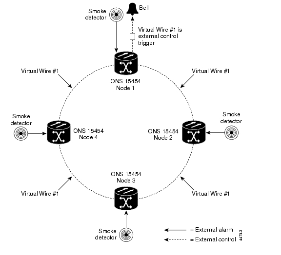
Provisioning the AIC card provides a "virtual wires" option that you can use to route external alarms and controls from different nodes to one or more alarm collection centers. In , smoke detectors at Nodes 1, 2, 3, and 4 are assigned to Virtual Wire #1, and Virtual Wire #1 is provisioned as the trigger for an external bell at Node 1.

Figure 5-6 AIC Virtual Wire Example

When using AIC virtual wires, you can:

Assign different external devices to the same virtual wire.

Assign virtual wires as the trigger type for different external controls.

Procedure: Provision External Alarms


Step 1 Wire the external-device relays to the ENVIR ALARMS IN backplane pins.

Step 2 Log into the node in CTC and display the AIC in card view.

Step 3 On the External Alarms subtab ( ), complete the following fields for each external device wired to the ONS 15454 backplane:

Enabled—click to activate the fields for the alarm input number.

Alarm Type—select an alarm type from the provided list.

Severity—select a severity. The severity determines how the alarm is displayed in the CTC Alarms and History tabs and whether the LEDs are activated. Critical, Major, and Minor activate the appropriate LEDs. Not Alarmed and Not Reported do not activate LEDs, but do report the information in CTC.

Virtual Wire—To assign the external device to a virtual wire, select the virtual wire. Otherwise, do not change the None default.

Raised When—select the contact condition (open or closed) that will trigger the alarm in CTC.

Description—default descriptions are provided for each alarm type; change the description as necessary.

Step 4 If you want to provision additional devices, complete Step 3 for each additional device.

Step 5 Click Apply.


Procedure: Provision External Controls


Step 1 Wire the external control relays to the ENVIR ALARMS OUT backplane pins.

Step 2 In CTC, log into the node and display the AIC in card view.

Step 3 On the External Controls subtab, complete the following fields for each external control wired to the ONS 15454 backplane:

Enabled—click to activate the fields for the alarm input number.

Trigger Type—select a trigger type: a local minor, major, or critical alarm, a remote minor, major, or critical alarm, or a virtual wire activation.

Description—enter a description.

Step 4 If you want to provision additional controls, complete Step 3 for each additional device.

Step 5 Click Apply.


5.4.2 Provisioning AIC Orderwire

The AIC provides RJ-11 jacks to allow onsite personnel to communicate with one another using standard phone sets. The AIC Local and Express orderwire channels are carried on the SONET Orderwire overhead:

Local orderwire is carried on the SONET Section layer E1 byte. Regenerators between ONS 15454 nodes terminate the channel.

Express orderwire is carried on the E2 byte of the SONET Line layer.

If regenerators are not used between ONS 15454 nodes, local or express AIC orderwire channels can be used. If regenerators exist, use the Express orderwire channel. You can provision up to four ONS 15454 optical carrier ports for each orderwire path.


Caution   When provisioning orderwire for ONS 15454s residing in a ring, do not provision a complete orderwire loop. For example, a four-node ring typically has east and west ports provisioned at all four nodes. However, to prevent orderwire loops from occurring, provision two orderwire ports (east and west) at all but one of the ring nodes.

Procedure: Provision AIC Orderwire


Tip Before you begin, make a list of the ONS 15454 slots and ports that require orderwire communication.


Step 1 In CTC, open the AIC card.

Step 2 Select the orderwire subtab appropriate to the orderwire path (Local Orderwire or Express Orderwire) that you want to create.

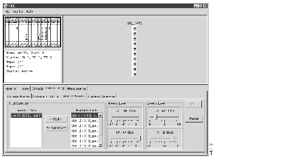
The Local Orderwire subtab is shown in Figure 5-7. Provisioning procedures are the same for both types.

Figure 5-7 AIC - Local Orderwire Subtab

Step 3 Under Available Ports, select each port that you want to use for the orderwire channel and click Add to move them to the Selected Ports column.

Step 4 If needed, adjust the Tx and Rx dBm by moving the slider to the right or left for the headset type (four-wire or two-wire) that you will use. (In general, you should not need to adjust the dBm.)

Step 5 Click Apply.


5.4.3 Using the AIC Orderwire

The AIC orderwire channels function as a party line. Anyone plugging a phone set into an AIC orderwire channel can communicate with all participants on the connected orderwire. The AIC does not provide private, point-to-point connections. To get the attention of participants, press the AIC Call button to activate a buzzer and illuminate the RING LED on AICs at all connected nodes.

5.5 Converting DS-1 and DS-3 Cards From 1:1 to 1:N Protection

The ONS 15454 provides several protection options for DS1-14 and DS3-12 cards: unprotected, 1:1, and 1:N. Changing protection from 1:1 to 1:N increases the available bandwidth because two of the three cards used for protection in the 1:1 protection group become working cards in the 1:N group.

When setting up 1:N protection, install the DS1N-14 or DS3N-12 card in Slot 3 or 15 on the same side of the ONS 15454 as the cards it protects. Slot 3 protects cards in Slots 1 - 2 and 4 - 6. Slot 15 protects Slots 12 - 14 and 16 - 17. A DS1N-14 or DS3N-12 card installed in Slot 3 or 15 can protect up to five DS1-14 or DS3-12 cards. If you install a DS3N-12 or DS1N-14 card in another slot, it behaves like a normal DS-1 or DS-3 card.

Procedure: Convert DS1-14 Cards From 1:1 to 1:N Protection


Note   This procedure assumes DS1-14 cards are installed in Slots 1 through 6 and/or Slots 12 through 17. The DS1-14 cards in Slots 3 and 15, which are the protection slots, will be replaced with DS1N-14 cards. The ONS 15454 must run CTC Release 2.0 or later. The procedure also requires at least one DS1N-14 card and a protection group with DS1-14 cards.


Step 1 Click the Maintenance>Protection tabs.

Step 2 Click the protection group that contains Slot 3 or Slot 15 (where the DS1N-14 will be installed).

Step 3 Make sure the slot you are upgrading is not carrying working traffic. Under Selected Group, the protect slot must say Protect/Standby (shown in Figure 5-8) and not Protect/Active. If the protect slot status is Protect/Active, use the following steps to switch traffic to the working card:

(a) Under Selected Group, click the protect card.

(b) From Operation at the bottom of the screen, select MANUAL.

(c) Click Apply.


Note   The working slot should change to Working/Active and the protect slot should change to Protect/Standby. If they do not change, do not continue. Troubleshoot the working card and slot to determine why the card cannot carry working traffic.


(d) From Operation, select CLEAR.

(e) Click Apply.

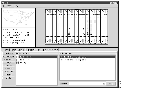
Figure 5-8 Protection Group Slot Status

Step 4 Repeat Steps 1-3 for each protection group that you need to convert. If you are only converting one protection group, proceed to Step 5.

Step 5 Verify that no standing alarms exist for any of the DS1-14 cards that you are converting.

Step 6 Clear any alarms that may exist on the DS1-14 cards before proceeding. If you have difficulty clearing alarms, contact your next level of support.

Step 7 Click the Provisioning>Protection tabs.

Step 8 Click the 1:1 protection group containing cards that will be moved into the new protection group.

Step 9 Click Delete.

Step 10 When the confirmation dialog displays, click Yes.


Note   Deleting the 1:1 protection groups does not disrupt service. However, no protection bandwidth exists for the working circuits until you complete the 1:N protection procedure. Therefore, complete this procedure as quickly as possible.


Step 11 If needed, repeat Steps 8 - 10 for other protection groups.

Step 12 On the node view shelf graphic, right-click the DS1-14 card in Slot 3 or Slot 15 and select Delete from the shortcut menu. Wait for the card to disappear from the node view.

Step 13 Physically remove the DS1-14 card from Slot 3 or Slot 15.

Step 14 Physically insert a DS1N-14 card in the same slot.

Step 15 Verify that the card boots up properly.

Step 16 Click the Inventory tab and verify that the new card appears as a DS1N-14.

Step 17 Click the Provisioning>Protection tabs.

Step 18 Click Create. The Create Protection Group dialog opens with the protect card in the Protect Card field and the available cards in the Available Cards field.

Step 19 Type a name for the protection group in the Name field (optional).

Step 20 Click Type and choose 1:N (card) from the pull-down menu.

Step 21 Verify that the DS1N-14 card appears in the Protect Card field.

Step 22 Under Available Cards, highlight the cards that you want in the protection group. Click the arrow (>>) tab to move the cards to the Working Cards list.

Step 23 Click OK. The protection group appears under Protection Groups on the Protection subtab.


Procedure: Convert DS3-12 Cards From 1:1 to 1:N Protection


Note   This procedure assumes that DS3-12 cards are installed in Slots 1 - 6 and/or Slots 12 - 17. The DS3-12 cards in Slots 3 and 15, which are the protection slots, will be replaced with DS3N-12 cards. The ONS 15454 must run CTC Release 2.0 or later. The procedure also requires at least one DS3N-12 card and a protection group with DS3-12 cards.


Step 1 Click the Maintenance>Protection tabs.

Step 2 Click the protection group containing Slot 13 or Slot 15 (where you will install the DS3N-12 card).

Step 3 Make sure the slot you are upgrading is not carrying working traffic. Under Selected Group, the protect slot must say Protect/Standby as shown in Figure 5-8, and not Protect/Active. If the protect slot status is Protect/Active, use the following steps to switch traffic to the working card:

(a) Under Selected Group, click the protect card.

(b) From Operation at the bottom of the screen, select MANUAL.

(c) Click Apply.


Note   The working slot should change to Working/Active and the protect slot should change to Protect/Standby. If they fail to change, do not continue. Troubleshoot the working card and slot to determine why the card cannot carry working traffic.


(d) From Operation, select CLEAR.

(e) Click Apply.

Step 4 If you are converting more than one protection group, repeat Step 2 for each group that needs conversion. Otherwise, proceed to Step 5.

Step 5 Verify that no standing alarms exist for any of the DS3-12 cards you are converting.


Note   Clear any alarms that may exist on the DS3-12 cards before proceeding. If you have difficulty clearing alarms, contact your next level of support.


Step 6 Click the Provisioning>Protection tabs.

Step 7 Click a 1:1 protection group containing cards that will be moved into the new protection group.

Step 8 Click Delete.

Step 9 When the confirmation dialog displays, click Yes.


Note   Deleting the 1:1 protection groups will not disrupt service. However, no protection bandwidth exists for the working circuits until the 1:N protection procedure is completed. Do not delay when completing this procedure.


Step 10 If you are deleting more than one protection group, repeat Steps 6 - 8 for each group. Otherwise, proceed to Step 11.

Step 11 On the node view shelf graphic, right-click the DS3-12 card in Slot 3 or Slot 15 and select Delete from the shortcut menu.

Step 12 Physically remove the DS3-12 card from Slot 3 or Slot 15. This raises an improper removal alarm.

Step 13 In node view, right-click the slot that held the removed card and select delete from the pull-down menu. Wait for the card to disappear from the node view.

Step 14 Physically insert a DS3N-12 in the same slot.

Step 15 Verify that the card boots up properly.

Step 16 Click the Inventory tab and verify that the new card appears as a DS3N-12.

Step 17 Click the Provisioning>Protection tabs.

Step 18 Click Create.

The Create Protection Group dialog shows the protect card in the Protect Card field and the available cards in the Available Cards field.

Step 19 Type a name for the protection group in the Name field (optional).

Step 20 Click Type and select 1:N (card) from the pull-down menu.

Step 21 Verify that the DS3N-12 card appears in the Protect Card field.

Step 22 Under Available Cards, highlight the cards that you want in the protection group. Click the arrow (>>) tab to move the cards to the Working Cards list.

Step 23 Click OK.

The protection group should appear under Protection Groups on the Protection subtab.


This completes the procedure for converting a DS3N-12 from 1:1 to 1:N protection. Repeat this process for all protection groups or nodes that need upgrading.

5.6 Upgrading XC Cards to XCVT

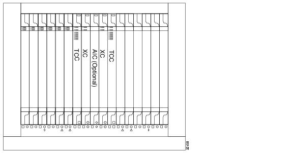
This section explains how to replace dual XC cards with dual XCVT cards in an ONS 15454 with live traffic. The substitution will not disrupt traffic. Figure 5-9 shows a ONS 15454 with XC cards installed.

Figure 5-9 ONS 15454 with XC Cards

Procedure: Upgrade XC Cards to XCVT

Upgrading XC cards to XCVT requires that the ONS 15454 run CTC Release 2.0 or later. Two XC cards must be installed in the ONS 15454, and two XCVT cards must be available for installation.
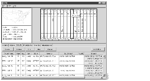

Step 1 Determine the standby XC card. The ACT/STBY LED of the standby XC card is yellow, while the ACT/STBY LED of the active XC card is green.


Note   You can also place the cursor on top of the card graphic to display a dialog. This display identifies the card as XC: Active or XC: Standby. Figure 5-10 shows an Active XC dialog.


Figure 5-10 Active XC Card

Step 2 Remove the standby XC card from the ONS 15454. This raises an improper removal alarm.

Step 3 Insert the first XCVT card into the empty XC slot and latch the levers.

The fail LED above the ACT/STBY LED becomes red, blinks for several seconds, then turns off.

The ACT/STBY LED turns yellow and stays lit.
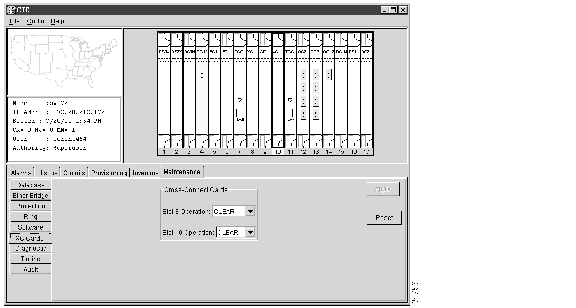
Step 4 In node view, select the Maintenance>XC Cards tabs ( Figure 5-11).

Figure 5-11 XC Cards Subtab

Step 5 Use the Slot Operation menu for the slot of the active card. In this example, Slot 10 Operation.

Step 6 Choose MANUAL from the pull-down menu.

Step 7 Click Apply.


Note   A minor alarm will appear on the manually switched slot. After the active XC disengages, the standby slot or first XCVT card becomes active. This causes the ACT/STBY LED on the first XCVT card to change from yellow to green.


Step 8 Choose CLEAR from the same Slot Operation menu.

Step 9 Click Apply.

Step 10 Physically remove the now standby XC card from the ONS 15454.

Step 11 Insert the second XCVT card into the empty XC slot. The second XCVT card boots up and becomes a standby XCVT.


hometocprevnextglossaryfeedbacksearchhelp

Posted: Mon Feb 25 07:35:47 PST 2008
All contents are Copyright © 1992--2008 Cisco Systems, Inc. All rights reserved.
Important Notices and Privacy Statement.