|
|

Table Of Contents
7.1 Ethernet over SONET Application
7.2 Router Aggregation Application
7.3 Transparent LAN Application
7.5 Virtual Local Area Networks (VLANs)
7.5.2 IEEE 802.1Q Priority Queuing (formerly IEEE 802.1P)
7.6.1 Spanning Tree Parameters
7.6.2 Spanning Tree Configuration
7.7 Multicard and Single-card EtherSwitch
7.8 ONS 15454 Ethernet Circuit Configurations
7.8.1 E-Series Circuit Protection
7.8.2 Multicard EtherSwitch Ethernet Circuit Provisioning
7.8.3 Shared Packet Ring Ethernet Circuit Provisioning
7.8.4 Hub and Spoke Ethernet Circuit Provisioning
7.8.5 Ethernet Manual Cross-Connects
7.9 VLAN Membership and Ethernet Port Provisioning
7.10 Ethernet Maintenance and Performance Screens
7.10.2 Line Utilization Screen
7.10.6 Trunk Utilization Screen
7.11 Remote Monitoring Specification Alarm Thresholds
7.12 Basic Ethernet Connectivity Testing
7
Ethernet Applications
This chapter explains how to use the Ethernet features of the Cisco ONS 15454.
7.1 Ethernet over SONET Application
To maximize Ethernet cost effectiveness, the ONS 15454 integrates Ethernet access into the same SONET platform that transports data and voice traffic. The ONS 15454 supports layer 2 switching and the ability to classify Ethernet traffic as defined in IEEE 802.1 Q. You can switch tagged traffic onto separate SONET STS channels to engineer bandwidth by traffic class. Ethernet over SONET lets service providers augment Time Division Multiplexing (TDM) services with Ethernet, and allows users to deliver data traffic over existing facilities. The ONS 15454 can also concentrate Ethernet ports into one or more STS-n circuits to use bandwidth more efficiently.
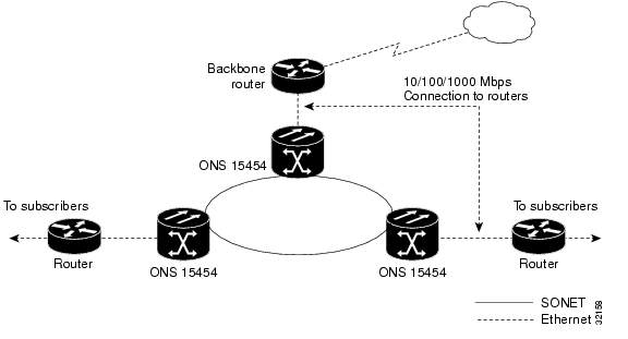
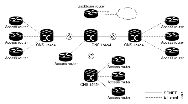
7.2 Router Aggregation Application
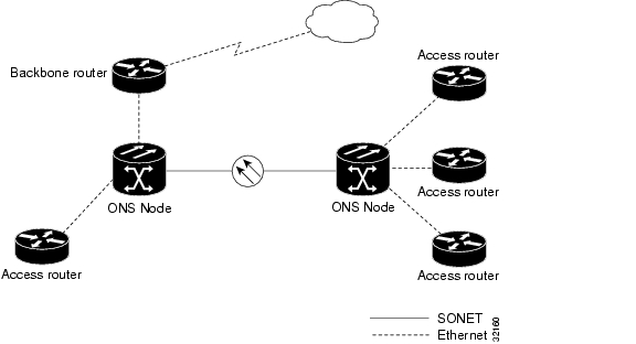
The ONS 15454 Ethernet solution uses existing SONET infrastructure to transport aggregate traffic from multiple, remote sources. illustrates the aggregation and transport.
Figure 7-1 Router Aggregation Application
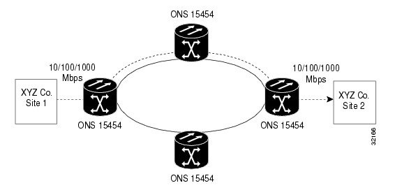
7.3 Transparent LAN Application
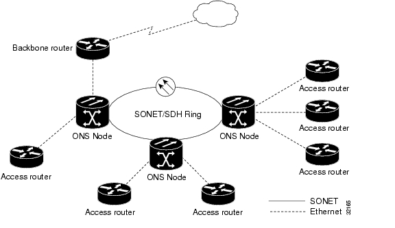
The ONS 15454 supports Transparent LAN Service (TLS) that provides private network service across a SONET backbone. Because network subscribers sometimes share the same equipment or even the same STS channels, it is necessary to logically isolate subscriber traffic. Service providers can use the IEEE 802.1Q feature in the ONS 15454 to define multiple, virtual local area networks (VLANs) across the backbone. Specific Ethernet ports and SONET STS channels can be defined as a VLAN group. VLAN groups isolate the subscriber's traffic from users outside the VLAN group and keep "outside" traffic from "leaking" into the VPN. illustrates a transparent LAN application.
Figure 7-2 Transparent LAN Application
7.4 ONS 15454 Ethernet Cards
The ONS 15454 supports two separate Ethernet cards, the E100T and the E1000-2. This section describes the characteristics of each card.
7.4.1 E100T
The ONS 15454 uses E100T cards for Ethernet (10 Mbps) and Fast Ethernet (100 Mbps). The E100T enables network operators to provide multiple 10/100 Mbps access drops for high-capacity customer LAN interconnections. The card provides efficient transport and co-existence of traditional TDM traffic with packet switched data traffic. The E100T eliminates the need for external Ethernet aggregation equipment.
Specifications:
•
Operating Temperature: 0 to +55 degrees Celsius
•
•
Figure 7-3 E100T Card, Front view
Table 7-1
Amber
Transmitting and Receiving
Solid Green
Idle and Link Integrity
Flashing Green
Transmitting only or Receiving only
Green Off
Inactive connection or uni-directional traffic.
E100T Ethernet Port LED States
7.4.2 E1000-2
The ONS 15454 uses the E1000-2 cards for Gigabit Ethernet (1000 Mbps). The E1000-2 enables network operators to provide multiple 1000 Mbps access drops for high-capacity customer LAN interconnections. The E1000-2 provides efficient transport and co-existence of traditional TDM traffic with packet-switched data traffic.
For Cisco Release 2.2.0, two GBIC modules are offered as separate products for flexibility: an IEEE 1000Base-SX compliant 850 nm optical module and an IEEE 1000Base-LX compliant 1300 nm optical module. The 850 nm SX optics are designed for multimode fiber and distances of up to
220 meters on 62.5 micron fiber and up to 550 meters on 50 micron fiber. The 1300 nm LX optics are designed for single-mode fiber and distances of up to 5 kilometers.
Caution
Specifications:
•
•
•
Figure 7-4 E1000-2 Card, Front view
Table 7-2
Amber
Transmitting and Receiving
Solid Green
Idle and Link Integrity
Flashing Green
Transmitting only or Receiving only
Green Off
Inactive connection or uni-directional traffic.
E1000-2 Ethernet Port LED States
7.5 Virtual Local Area Networks (VLANs)
As Ethernet networks grow, too many hosts transmitting data within a single broadcast domain cause an increase in "broadcast storms." You can create VLANs with the CTC to partition the broadcast domain into several domains and decrease the likelihood of broadcast storms. A VLAN carves out its own single broadcast domain from the larger Ethernet network.
The ONS 15454 supports port-based VLANs that group ports into virtual workgroups. These VLANs ensure that Ethernet ports see only traffic from ports within the same VLAN. These different VLANs communicate with each other through a router that spans multiple VLANs by using router ports in each VLAN, or through a router that understands IEEE 802.1Q.
7.5.1 IEEE 802.1Q
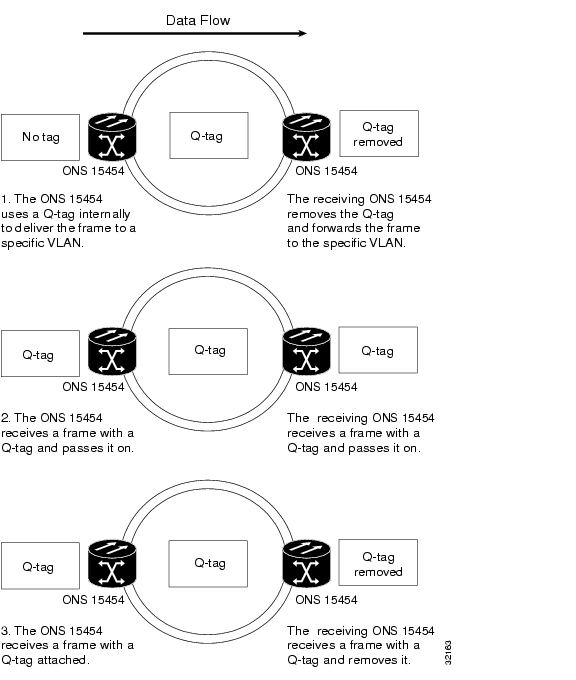
IEEE 802.1Q, the VLAN standard, places a Q-tag in the frame header. The 802.1Q-aware devices look at Q-tags to differentiate LANs. Therefore, multiple 802.1Q VLANs representing different logical networks can be transported over the same physical port. If a frame is received without a Q-tag, the frame is given a Q-tag based on the default VLAN assigned to the ingress port. If a frame is received with a Q-tag attached, the port classifies the frame based on the VLAN identifier present in the Q-tag.
Many older Ethernet devices do not understand 802.1Q tagging. Because 802.1Q lengthens the Ethernet header, older (non-802.1Q) devices may incorrectly identify the 802.1Q tagged packets as giants (an Ethernet frame larger than 1518 bytes) and drop them. The ONS 15454 takes non-tagged packets from the ingress port and assigns the frame to the VLAN associated with the ingress port. If packets come into the ONS 15454 network already tagged, the ONS 15454 uses the already-attached tag to forward the packet accordingly. Figure 7-5 illustrates different ways the ONS 15454 performs 802.1Q tagging.
The CTC allows the user to assign specific ports to specific VLANs and prohibit ports from being part of specific VLANs. ONS 15454 ports can also be set to Untag or Tagged. See the "Provision Ethernet Ports for VLAN Membership" section for more information on these operations.
Figure 7-5 Q-tag
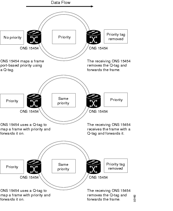
7.5.2 IEEE 802.1Q Priority Queuing (formerly IEEE 802.1P)
Priority Queuing eases network congestion by mapping Ethernet traffic to different priority levels. Networks without Priority Queing handle all packets on a first-in-first-out basis. Priority Queuing assigns priorities to data packets. The ONS 15454 uses a "leaky bucket" algorithm to establish a weighted priority (not a strict priority). A weighted priority gives high-priority packets greater access to bandwidth, but does not totally preempt low priority packets. 70% of bandwidth goes to the high priority que and the remaining 30% goes to the low priority que. Low priority packets can also be dropped when the network is congested. The ONS 15454 takes the eight priorities specified in IEEE 802.1Q and maps them to two queues (shown in ). Priority Queuing information is carried through the network via IEEE 802.1Q tags
.
Figure 7-6 Priority Queuing
7.6 Spanning Tree
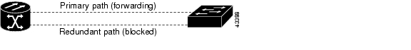
STP detects and eliminates network loops. By default, the ONS 15454 uses IEEE 802.1D STP on the optical line interfaces. When STP detects multiple paths between any two network hosts, STP blocks ports until only one path exists between any two network hosts ( ). The single path eliminates possible bridge loops.
Figure 7-7 Spanning Tree Blocked Path
When loops occur, some Ethernet switches see the same stations transmitting data on more than one interface. This condition disables the forwarding algorithm and allows duplicate frames to be forwarded. To remove loops, STP defines a tree that spans all the switches in an extended network. STP forces certain redundant data paths into a standby (blocked) state. If one network segment in the STP becomes unreachable, the spanning-tree algorithm reconfigures the spanning-tree topology and reactivates the blocked path to re-establish the link. STP operation is transparent to end stations, which do not discriminate between connections to a single LAN segment or a switched LAN with multiple segments. The ONS 15454 supports one STP instance per circuit up to a maximum of eight instances per shelf.
Starting with Release 2.2.0, users have the ability to enable STP on the Ethernet ports of the E100 and E1000 cards. This allows redundant circuit paths to be available for additional fault tolerance, but not cause a loop, as they are blocked by STP.
Figure 7-8 Enabling Spanning Tree
Procedure: Enable Spanning Tree on Ethernet Ports
Step 1
Step 2
Step 3
7.6.1 Spanning Tree Parameters
Default spanning tree parameters are appropriate for most situations. Contact the Technical Assistance Center (TAC) at 1-877-323-7368 before you change the default STP parameters.
At the node view click the Maintenance>Spanning Trees> Etherbridge tabs to view spanning tree parameters.
Figure 7-9 Spanning Tree Parameters
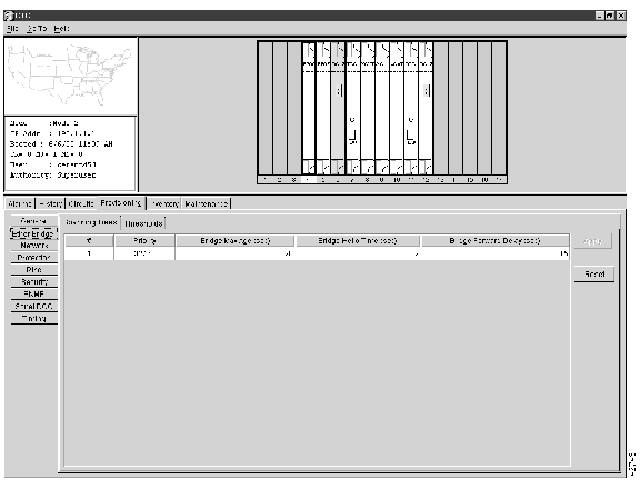
7.6.2 Spanning Tree Configuration
To view the spanning tree configuration, at the node view click the Provisioning tab and Etherbridge subtab.
Figure 7-10 Spanning Tree Configuration
Table 7-5
Priority
32768
0-65535
Bridge max age
20 seconds
6-40 seconds
Bridge Hello Time
2 seconds
1-10 seconds
Bridge Forward Delay
15 seconds
4-30 seconds
Spanning Tree Configuration
7.6.3 Viewing Spanning Tree
Figure 7-11 Circuit Screen
Procedure: View Spanning Tree
Step 1
Step 2
Note
7.7 Multicard and Single-card EtherSwitch
Release 2.0 of the ONS 15454 used multicard EtherSwitch exclusively. As Ethernet cards were added within a shelf, they would combine to form a single layer 2 switch. The bandwidth of the single switch formed by the Ethernet cards matches the bandwidth of the provisioned Ethernet circuit up to STS-6C worth of bandwidth. Figure 7-12 illustrates a multicard EtherSwitch configuration.
Figure 7-12 Multicard EtherSwitch
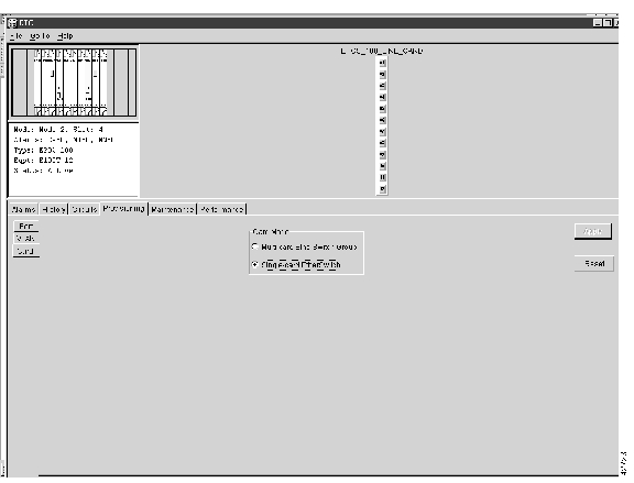
In Release 2.2.0 and later, single-card EtherSwitch Ethernet is an additional option that allows each Ethernet card to remain a single switching entity within the ONS 15454 shelf. Both E100 and E1000 cards allow either multicard EtherSwitch or single-card EtherSwitch operation. Single-card EtherSwitch allows a full STS-12C worth of bandwidth between two Ethernet circuit points.
Figure 7-13 illustrates a single-card EtherSwitch configuration.Figure 7-13 Single-card EtherSwitch
Seven scenarios for provisioning single-card EtherSwitch bandwidth are possible:
1
2
3
4
5
6
7
Note
Note
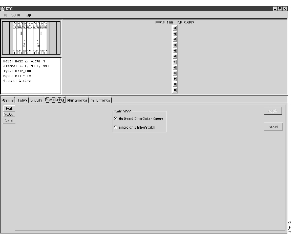
illustrates the Card Mode screen where the EtherSwitch option is provisioned.
Figure 7-14 Card Mode
7.8 ONS 15454 Ethernet Circuit Configurations
There are three common methods for configuring Ethernet circuits between ONS 15454 nodes: a straight circuit configuration, a shared packet ring configuration, and a hub and spoke configuration. Two nodes usually connect with a straight circuit configuration. More than two nodes usually connect with a shared packet ring configuration or a hub and spoke configuration.
Figure 7-15 shows a straight circuit configuration, Figure 7-16 shows a shared packet ring configuration, and shows a hub and spoke configuration.
Figure 7-15 Straight Circuit Configuration
Figure 7-16 Shared Packet Ring Ethernet Circuit Configuration
Figure 7-17 Hub and Spoke Ethernet Circuit Configuration
7.8.1 E-Series Circuit Protection
Different combinations of E-Series circuit configurations and SONET network topologies offer different levels of E-Series circuit protection. details the available protection.
Caution
Note
Note
7.8.2 Multicard EtherSwitch Ethernet Circuit Provisioning
Procedure: Provision a Multicard Straight Ethernet Circuit
Note
Figure 7-18 Multicard Straight Circuit
Step 1
Step 2
Step 3
Figure 7-19 Card Mode Window
Step 4
Step 5
Step 6
Step 7
Step 8
Step 9
Step 10
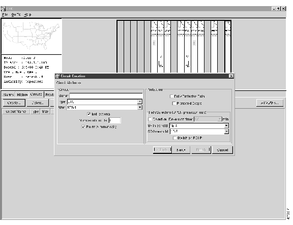
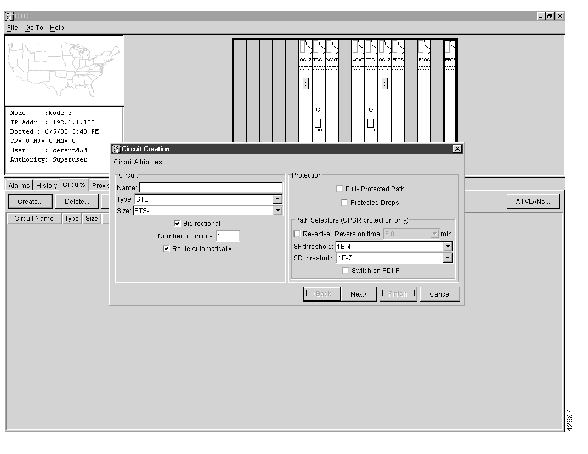
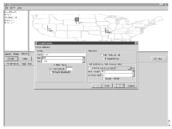
The Circuit Attributes dialog opens (see ).
Figure 7-20 Circuit Attributes Dialog
Step 11
Step 12
Note
Step 13
Note
Step 14
Step 15
Step 16
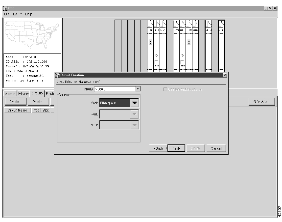
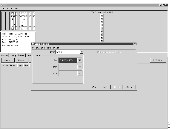
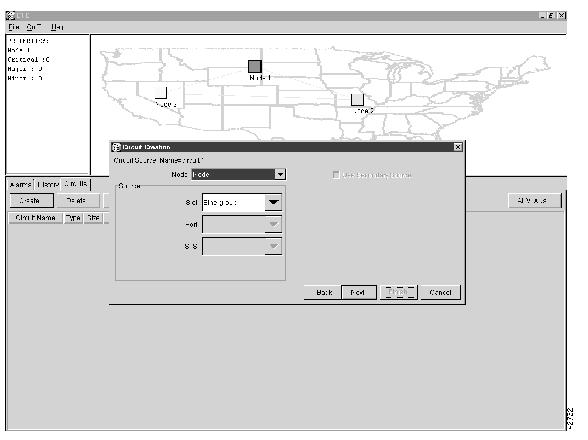
Figure 7-21 Circuit Source
Step 17
Note
Step 18
Step 19
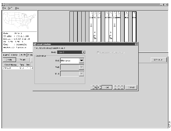
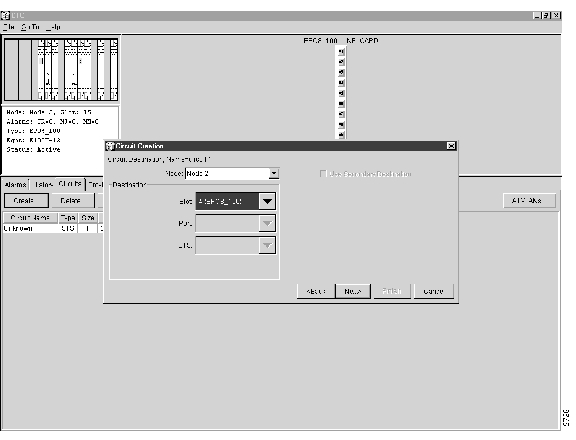
Figure 7-22 Circuit Destination
Step 20
Step 21
Step 22
The Circuit VLAN Selection window displays (see ).
Note
Step 23
(a)
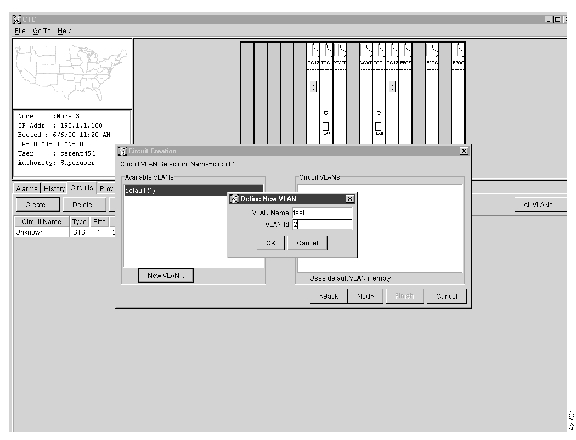
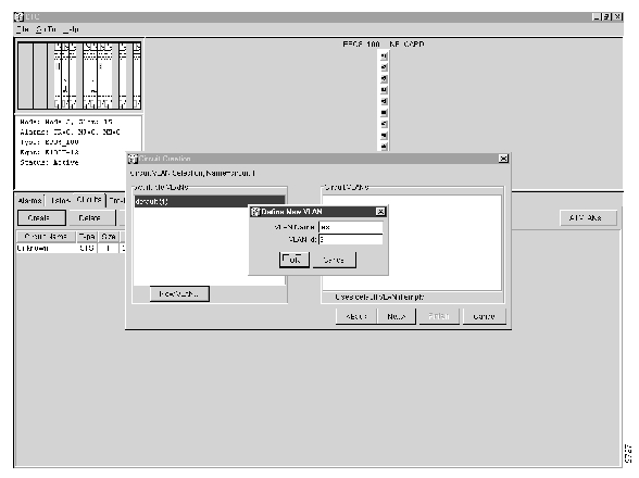
The Define New VLAN dialog opens (see ).
Figure 7-23 Define New VLAN Dialog
(b)
(c)
This should be the next available number between 2 and 4093 that is not already assigned to an existing VLAN. Each ONS 15454 network supports a maximum of 509 user provisionable VLANs.
(d)
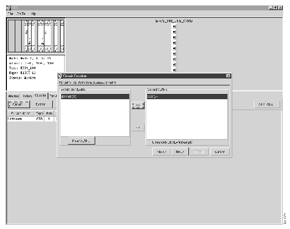
Figure 7-24 Circuit VLAN Selection
(e)
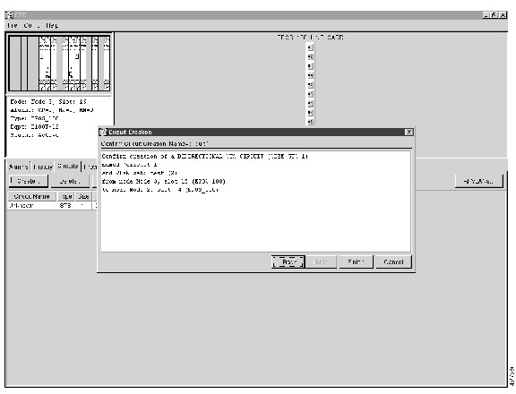
Step 24
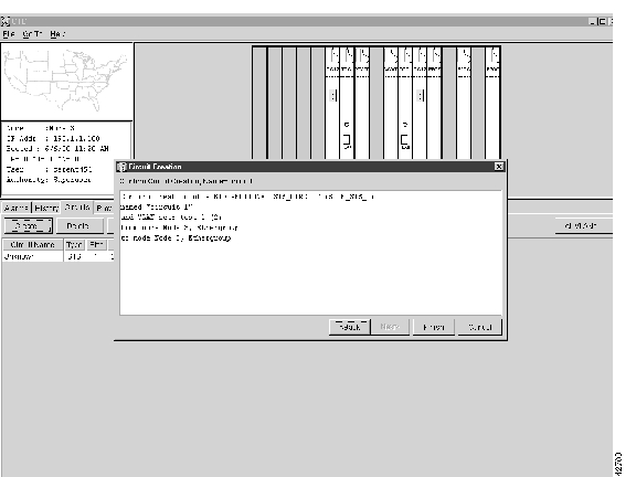
Figure 7-25 Circuit Confirmation
Step 25
•
•
•
•
•
Note
Step 26
You now need to provision the Ethernet ports and assign these ports to VLANs. For port provisioning instructions, see the "VLAN Membership and Ethernet Port Provisioning" section. For information about manually provisioning circuits, see the "Ethernet Manual Cross-Connects" section.
Procedure: Provision a Single Card Ethernet Straight Circuit
Figure 7-26 Single-card Straight Circuit
Step 1
Step 2
Step 3
Figure 7-27 Single-card EtherSwitch Screen
Step 4
Step 5
Step 6
Step 7
Step 8
Step 9
The Circuit Attributes window opens.
Figure 7-28 Circuit AttributesDialog
Step 10
Step 11
Note
Step 12
Step 13
Step 14
Step 15
Figure 7-29 Circuit Source
Step 16
Note
Step 17
Step 18
Figure 7-30 Circuit Destination
Step 19
Note
Step 20
Step 21
The Circuit VLAN Selection window displays. See .
Note
Step 22
(a)
The Define New VLAN dialog opens.
Figure 7-31 Define New VLAN Dialog
(b)
(c)
This should be the next available number (between 2 and 4093) not already assigned to an existing VLAN. Each ONS 15454 network supports a maximum of 509 user provisionable VLANs.
(d)
(e)
Figure 7-32 Circuit VLAN Selection
Step 23
Figure 7-33 Circuit Confirmation
The Confirm Circuit Creation dialog opens and displays the following information about the point-to-point circuit (see ):
•
•
•
•
•
Note
Step 24
You now need to provision the Ethernet ports and assign these ports to VLANs. For port provisioning instructions, see the "VLAN Membership and Ethernet Port Provisioning" section. For information about manually provisioning circuits, see the "Ethernet Manual Cross-Connects" section.
7.8.3 Shared Packet Ring Ethernet Circuit Provisioning
This section provides steps for creating a shared packet ring. Figure 7-34 illustrates a sample shared packet ring. (Your network architecture may differ from the example.)
Figure 7-34 Shared Packet Ring
Procedure: Provision a Shared Packet Ring
Step 1
Step 2
Step 3
Figure 7-35 Multicard EtherSwitch Group
Step 4
Step 5
Step 6
Step 7
Step 8
Step 9
Step 10
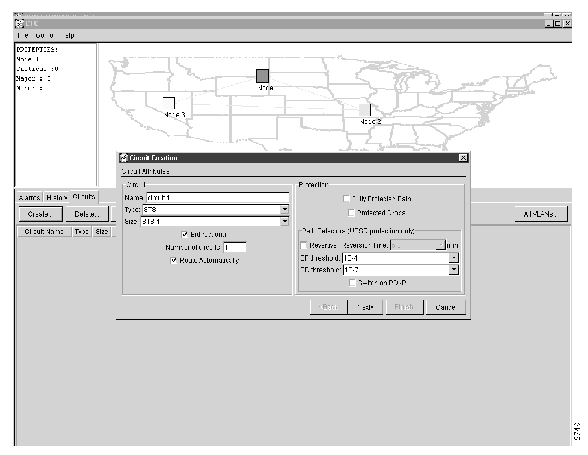
The Circuit Creation dialog opens (see ).
Figure 7-36 Circuit Attributes Dialog
Step 11
Step 12
Step 13
Note
Step 14
Step 15
Note
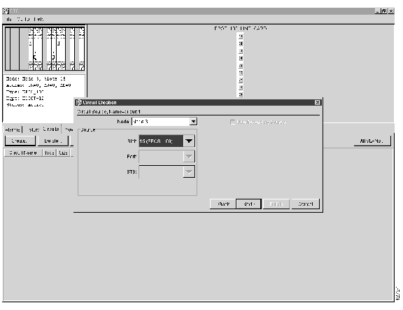
Step 16
Figure 7-37 Circuit Source Dialog
Step 17
Note
Step 18
Step 19
Step 20
Note
Step 21
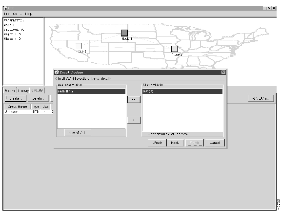
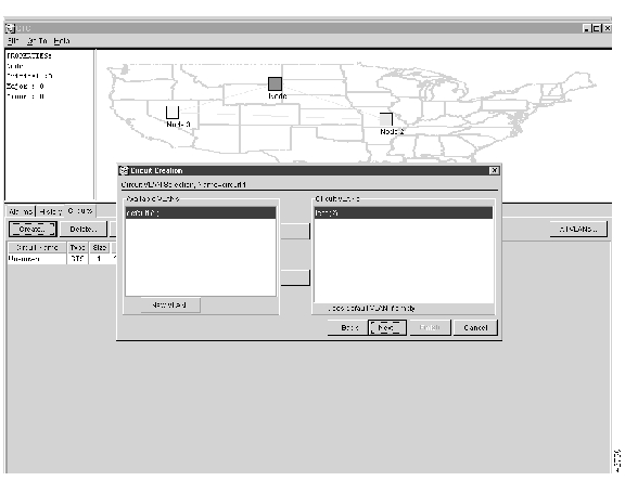
Figure 7-38 Circuit VLAN Selection
Step 22
The Circuit VLAN Selection window opens (see ).
Note
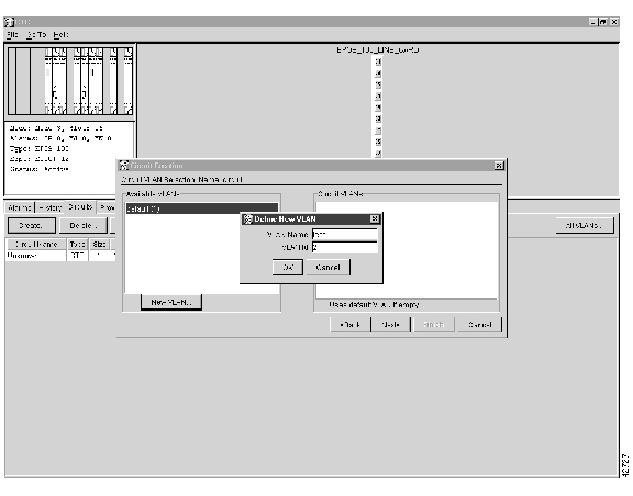
Step 23
(a)
The Define New VLAN dialog opens.
(b)
(c)
This VLAN ID number must be unique. It is usually the next available number not already assigned to an existing VLAN (between 2 and 4093). Each ONS 15454 network supports a maximum of 509 user-provisionable VLANs.
(d)
(e)
By moving the VLAN from the Available VLANs column to the Circuit VLANs column, all the VLAN traffic is forced to use the shared packet ring circuit you created.
Step 24
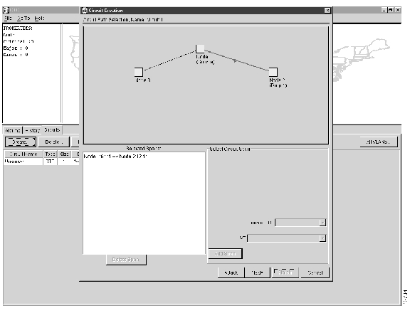
Figure 7-39 Circuit Path Selection
Step 25
Step 26
The menu shows the STSs available to carry the shared packet ring circuit.
Step 27
Step 28
Step 29
Note
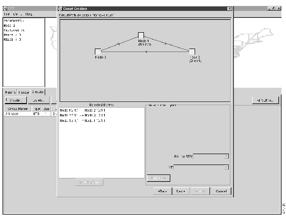
Figure 7-40 Circuit Path Selection (all spans)
Step 30
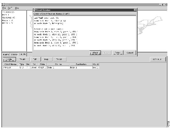
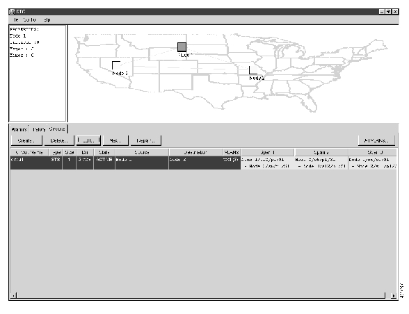
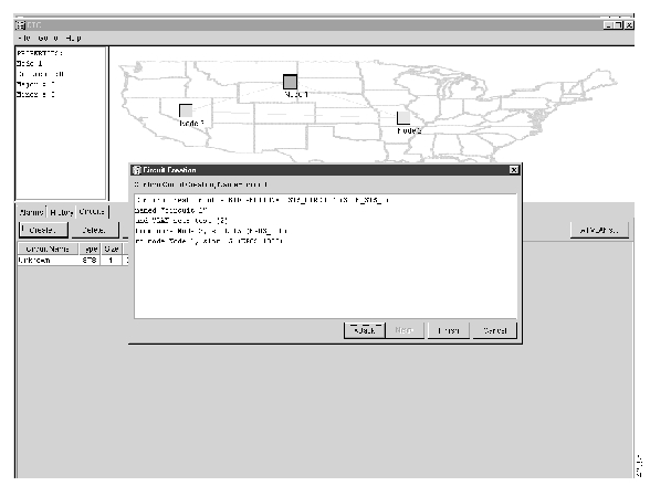
Figure 7-41 Circuit Creation
Step 31
Note
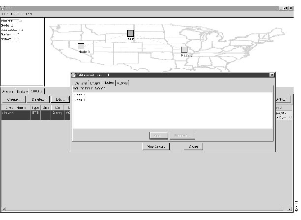
Step 32
Step 33
(a)
Figure 7-42 Highlighted Circuit Path
(b)
Figure 7-43 Edit Circuit Dialog Box
(c)
(d)
(e)
(f)
(g)
(h)
You now need to provision the Ethernet ports and assign ports to VLANs. For instructions on port provisioning, see the "VLAN Membership and Ethernet Port Provisioning" section. For information about manually provisioning Ethernet circuits, see the "Ethernet Manual Cross-Connects" section.
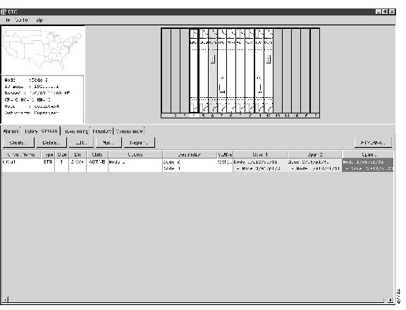
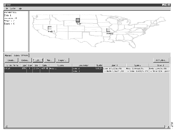
Figure 7-44 shows a completed shared packet ring circuit.
Figure 7-44 Completed Shared Packet Ring Circuit
7.8.4 Hub and Spoke Ethernet Circuit Provisioning
This section provides steps for creating a hub and spoke Ethernet circuit configuration. The hub and spoke configuration connects point-to-point circuits (the spokes) to an aggregation point (the hub). In many cases, the hub is an E1000-2 card that links to a high-speed connection and the spokes are E100T cards. illustrates a sample hub spoke ring. (Your network architecture may differ from the example.)
Figure 7-45 Hub and Spoke Ethernet Circuit
Procedure: Provision a Hub and Spoke Ethernet Circuit
Step 1
Step 2
Step 3
Figure 7-46 Single-card EtherSwitch Screen
Step 4
Step 5
Step 6
Step 7
Step 8
Step 9
The Circuit Attributes dialog opens (shown in ).
Figure 7-47 Circuit Attributes Dialog
Step 10
Step 11
Note
Step 12
Step 13
Step 14
Step 15
Figure 7-48 Circuit Source
Step 16
Note
Step 17
Step 18
Step 19
Note
Step 20
Step 21
The Circuit VLAN Selection dialog displays.
Figure 7-49 Circuit VLAN Selection
Note
Step 22
(a)
The Define New VLAN dialog opens (see Figure 7-49).
(b)
(c)
This should be the next available number (between 2 and 4093) not already assigned to an existing VLAN. Each ONS 15454 network supports a maximum of 509 user-provisionable VLANs.
(d)
Figure 7-50 Selected VLANs
(e)
Step 23
Figure 7-51 Circuit Confirmation
The Confirm Circuit Creation dialog opens and displays the following information about the point-to-point circuit (see Figure 7-51):
•
•
•
•
•
Note
Step 24
You must now provision the second circuit and attach it to the already-created VLAN.
Step 25
Step 26
Step 27
Step 28
Step 29
Step 30
Step 31
Step 32
Step 33
Step 34
Note
Step 35
Step 36
Step 37
Step 38
Step 39
Note
Step 40
Step 41
Note
Step 42
Step 43
The Circuit VLAN Selection dialog is displayed.
Note
Step 44
Step 45
Step 46
You now need to provision the Ethernet ports and assign the ports to VLANs. For instructions about port provisioning, see the "VLAN Membership and Ethernet Port Provisioning" section. For information about assigning Ethernet ports to VLANs, see the "Provision Ethernet Ports for VLAN Membership" section.
7.8.5 Ethernet Manual Cross-Connects
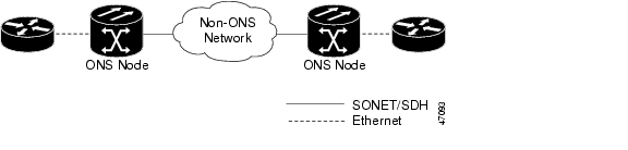
ONS 15454s require end-to-end CTC visibility between nodes for normal provisioning of Ethernet circuits. When other vendors' equipment sits between ONS 15454s, OSI/TARP- based equipment does not allow tunneling of the ONS 15454 TCP/IP-based DCC. To circumvent this lack of continuous DCC, the Ethernet circuit must be manually cross-connected to an STS channel riding through the non-ONS network. This allows an Ethernet circuit to run from ONS node to ONS node utilizing the non-ONS network.
Note
Caution
Figure 7-52 Ethernet manual cross-connects
Procedure: Provision a Single-card Etherswitch Manual Cross-Connect
Step 1
Step 2
Step 3
Step 4
If the Single-card EtherSwitch is not checked, check it and click Apply.
Step 5
Step 6
The Circuit Creation (Circuit Attributes) dialog box opens ( ).
Figure 7-53 Creating an Ethernet circuit
Step 7
Step 8
The types VT and VT Tunnel do not apply to Ethernet circuits.
Step 9
The valid circuit sizes for an Ethernet Multicard circuit are STS-1, STS-3c and STS-6c.
Step 10
The Circuit Creation (Circuit Source) dialog box opens.
Step 11
Step 12
The Circuit Creation (Circuit Destination) dialog box opens.
Step 13
Step 14
Step 15
Note
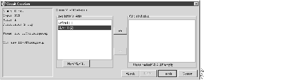
The Circuit Creation (Circuit VLAN Selection) dialog box opens ( ).
Note
Step 16
(a)
The Circuit Creation (Define New VLAN) dialog box opens ( ).
(b)
(c)
The VLAN ID should be the next available number (between 2 and 4093) that is not already assigned to an existing VLAN. Each ONS 15454 network supports a maximum of 509 user-provisionable VLANs.
(d)
Figure 7-54 Selecting VLANs
(e)
Step 17
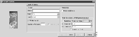
The Circuit Creation (Circuit Routing Preferences) dialog box opens.
Step 18
•
•
•
•
•
Note
Step 19
You now need to provision the Ethernet ports and assign these ports to VLANs. For port provisioning instructions, see the "VLAN Membership and Ethernet Port Provisioning" section. Return to the following step after assigning the ports to VLANs.
Step 20
Note
Procedure: Provision a Multi-card Etherswitch Manual Cross-Connect
Step 1
Step 2
Step 3
Step 4
If the Multicard-card EtherSwitch is not checked, check it and click Apply.
Step 5
Step 6
Step 7
The Circuit Creation (Circuit Attributes) dialog box opens ( ).
Figure 7-55 Creating an Ethernet circuit
Step 8
Step 9
The types VT and VT Tunnel do not apply to Ethernet circuits.
Step 10
The valid circuit sizes for an Ethernet Multicard circuit are STS-1, STS-3c and STS-6c.
Step 11
The Circuit Creation (Circuit Source) dialog box opens.
Step 12
Step 13
The Circuit Creation (Circuit Destination) dialog box opens.
Step 14
Step 15
Note
The Circuit Creation (Circuit VLAN Selection) dialog box opens ( ).
Note
Step 16
(a)
(b)
(c)
The VLAN ID should be the next available number (between 2 and 4093) that is not already assigned to an existing VLAN. Each ONS 15454 network supports a maximum of 509 user-provisionable VLANs.
(d)
Figure 7-56 Selecting VLANs
(e)
Step 17
The Circuit Creation (Circuit Routing Preferences) dialog box opens.
Step 18
•
•
•
•
•
Note
Step 19
You now need to provision the Ethernet ports and assign these ports to VLANs. For port provisioning instructions, see the "VLAN Membership and Ethernet Port Provisioning" section. Return to the following step after assigning the ports to VLANs.
Step 20
The Edit Circuit dialog box opens.
Step 21
The Define New Drop dialog box opens.
Step 22
Step 23
Step 24
Step 25
The Edit Circuit dialog box opens.
Step 26
Step 27
Note
7.9 VLAN Membership and Ethernet Port Provisioning
This section explains how to provision Ethernet ports, including provisioning Ethernet ports for VLAN membership.
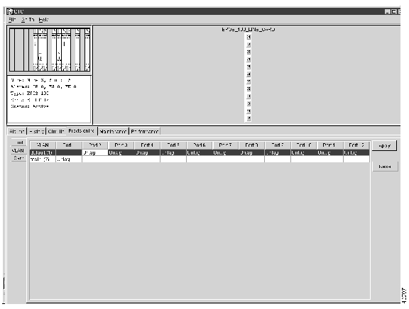
Procedure: Provision Ethernet Ports for VLAN Membership
Note
The ONS 15454 allows you to configure the VLAN membership and the Q-tag handling of individual Ethernet ports.
Step 1
Figure 7-57 VLAN Port Provisioning Screen
Step 2
If a port belongs to only one VLAN, go to that VLAN's row and choose Untag from that port's column. Choose -- for all the other VLAN rows under that port. This allows the VLAN with Untag selected to access that port and prohibits the other VLANS with -- selected to access the port.
If a port is a trunk port, it connects multiple VLANs to an external device, such as a router. This port must have tagging (8021.Q) enabled for all the VLANs that connect to the external device. Choose Tagged at each VLAN row in the trunk port column. Choose Untag in the default VLAN row in the column under the trunk port's heading.
Note
Step 3
Note
Procedure: Provision E1000-2 Ethernet Ports
Step 1
Step 2
Step 3
Note
shows the Provisioning menu screen with the Port subtab selected.
Figure 7-58 Port Provisioning Screen
Step 4
Step 5
Note
Step 6
Your Ethernet ports are now provisioned and ready to be configured for VLAN membership (see the "Provision Ethernet Ports for VLAN Membership" section).
Procedure: Provision E100T-12 Ethernet Ports
Step 1
Step 2
Step 3
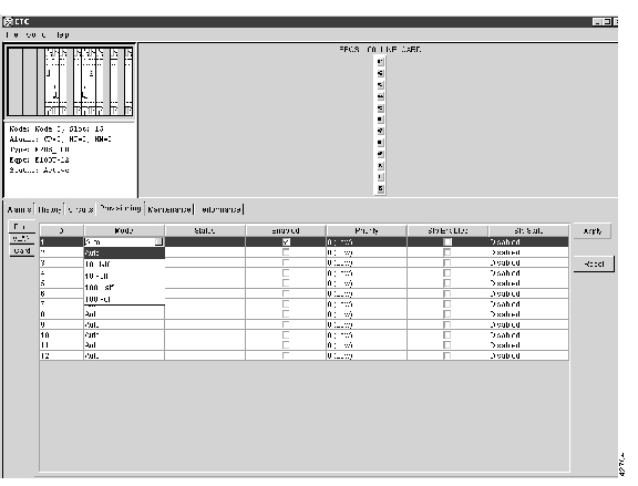
shows the Provisioning menu screen with the Port function subtab selected.
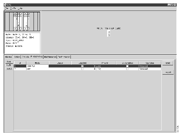
Figure 7-59 Port Provisioning Screen
Step 4
Step 5
Most provisioning requires filling in two fields: Enabled and Mode. However, the user may also map incoming traffic to a low priority or a high priority using the Priority column or enable spanning tree with the Stp Enabled column. The Status column displays information about the port's current operating mode, and the Stp State column gives the current Spanning tree status.
Step 6
Your Ethernet ports are now provisioned and ready to be configured for VLAN membership (see the "Provision Ethernet Ports for VLAN Membership" section).
7.10 Ethernet Maintenance and Performance Screens
The CTC provides several screens of information to help manage and maintain Ethernet performance.
7.10.1 Statistics Screen
The Ethernet statistics screen lists Ethernet parameters at the port level. defines the parameters. Click the Performance and Statistics tabs at the card level view to display the screen (see ).
Figure 7-60 Ethernet Statistics
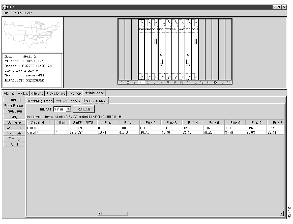
7.10.2 Line Utilization Screen
The Line Utilization screen shows the percentage of line or port bandwidth currently used and the percentage used in the past. Click the Performance and Utilization tabs at the Ethernet card view to display the screen (see ). At the Interval drop-down menu, choose a time segment variable for the intervals. Valid intervals are 1 minute, 15 minutes, 1 hour, and 1 day.
Note
Figure 7-61 Line Utilization
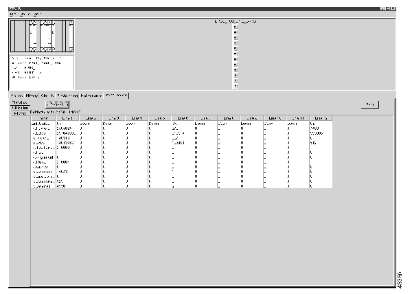
7.10.3 History Screen
The Ethernet History screen lists past Ethernet statistics. Choose the appropriate port from the Line menu. defines the listed parameters. At the Ethernet card view, click the Performance tab and History subtab to view the screen (shown in ).
Figure 7-62 Ethernet History
7.10.4 Spanning Trees Screen
The Spanning Trees screen lists information about spanning trees on the ONS 15454. Click the Maintenance>EtherBridge>Spanning Trees tabs to view the screen (shown in ). For more information about spanning trees and the ONS 15454, see the "Spanning Tree" section.
Figure 7-63 Spanning Tree Topology
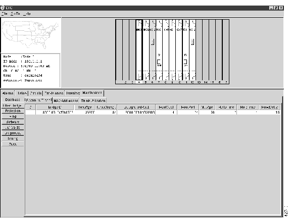
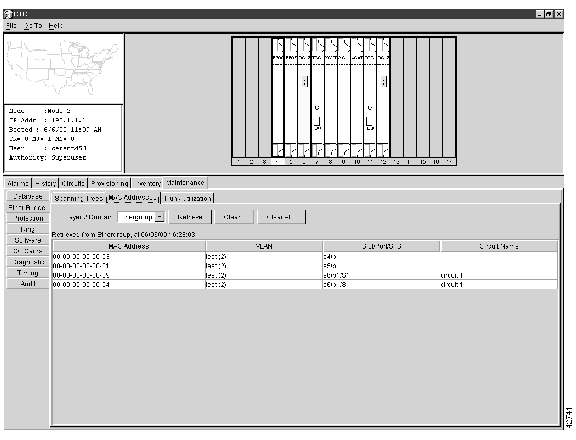
7.10.5 MAC Addresses Screen
A MAC address is a hardware address that physically identifies the equipment attached to the ONS 15454 port or the network attached to the port. The MAC addresses table (also called the MAC forwarding table) lists the MAC Addresses stored by the ONS 15454 and the VLAN, Slot/Port/STS, and circuit that links the ONS 15454 to each MAC address (see ).
Figure 7-64 MAC Addresses Discovered
Click the Maintenance>EtherBridge>MAC Addresses tabs to view the screen (see ).
•
•
•
Figure 7-65 MAC Forwarding Table
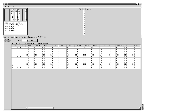
7.10.6 Trunk Utilization Screen
The Trunk Utilization screen is similar to the Line Utilization screen, but the Trunk Utilization screen shows the percentage of circuit bandwidth being used rather than the percentage of line bandwidth being used. Choose a time segment variable for the intervals at the Interval menu. Click the Maintenance>EtherBridge>Trunk Utilization tabs to view the screen (shown in ).
Note
Figure 7-66 Trunk Utilization
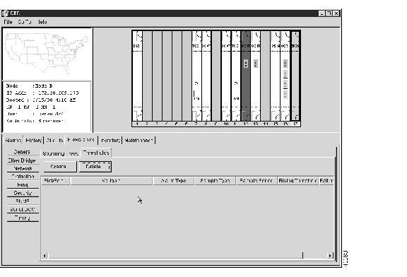
7.11 Remote Monitoring Specification Alarm Thresholds
The ONS 15454 features SNMP Remote Network Monitoring (RMON) that allows network operators to monitor the health of the network with a Network Management System (NMS). For a complete list of the implemented RMON Management Information Bases (MIBs), see the "SNMP Remote Network Monitoring" section on page 8-8.
One of the ONS 15454's RMON MIBs is the Alarm group. The alarm group contains the alarmTable. An NMS uses the alarmTable to find the alarm-causing thresholds for network performance. The thresholds apply to the current 15-minute interval and the current 24-hour interval. The RMON monitors several variables, such as Ethernet collisions, and triggers an event when the variable crosses a threshold during that time interval. For example, if a threshold is set at 1000 collisions and 1001 collisions occur during the 15-minute interval, an event triggers.
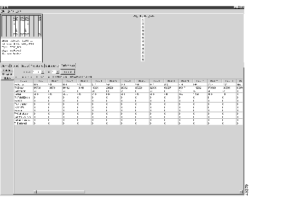
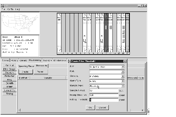
CTC allows you to provision these thresholds for Ethernet statistics. The following tables define the variables provisioned in the CTC. For example, to set the collision threshold, click etherStatsCollisions in the Variable menu.
Procedure: Creating Ethernet Thresholds
Figure 7-67 Ethernet Alarm Screen
Step 1
Step 2
Step 3
The Create Ether Threshold menu appears.
Figure 7-68 Ethernet Alarm Thresholds
Step 4
Step 5
Step 6
Step 7
Step 8
Step 9
Step 10
Note
Step 11
Note
Step 12
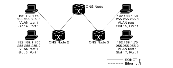
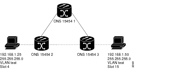
7.12 Basic Ethernet Connectivity Testing
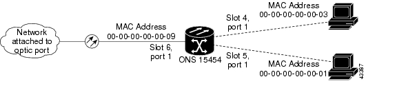
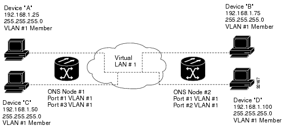
Most connectivity problems experienced in an Ethernet network can be fixed by following a few guidelines. Refer to this section if you have problems connecting Ethernet networks. See when consulting these guidelines.
Figure 7-69 Ethernet Connectivity Reference
Procedure: Test Ethernet Connectivity
Step 1
circuit.Step 2
Step 3
Step 4
(a)
(b)
(c)
Step 5
(a)
(b)
(c)
Step 6
Verify that the Ethernet circuit that carries VLAN #1 is provisioned and that both ONS 15454 #1 and ONS 15454 #2 are included in the VLAN #1 circuit.
![]()
![]()
![]()
![]()
![]()
![]()
![]()
![]()
Posted: Mon Feb 25 07:56:18 PST 2008
All contents are Copyright © 1992--2008 Cisco Systems, Inc. All rights reserved.
Important Notices and Privacy Statement.