|
|

Table Of Contents
6.2.1 Optical Transmitters and Transponders
6.2.3 Optical Multiplexers and Demultiplexers
6.4.1 ONS 15454 OC48 ELR ITU Optics
6.4.2 Using the ONS 15454 in a DWDM Network
6
DWDM
This chapter provides a general overview of Dense Wavelength Division Multiplexing (DWDM) technology, components, and applications and describes how the Cisco ONS 15454 implements DWDM solutions.
6.1 DWDM Overview
DWDM increases the information-carrying capacity of existing fiber optic infrastructure to eliminate the high cost of installing new fiber optic cable. The majority of the current high-speed backbones used by service providers are comprised of fiber optic links operating at 2.5 Gigabits per second (Gbps) or 10 Gbps. DWDM offers a scalable solution for using existing installed fiber optics to gain increased bandwidth.
DWDM transmits multiple signals simultaneously at different wavelengths. This allows a single fiber to operate as if it were multiple fibers, referred to as "virtual fiber." Each signal carried can be at a different rate (OC-48 or OC-192 for example ) yet use the same physical fiber optic cable.
6.2 DWDM Components
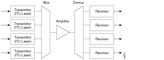
All DWDM systems consist of the following components: precise wavelength optical transmitters (lasers), optical multiplexers (mux) and demultiplexers (demux), and broadband optical receivers . Optional components of a DWDM system are optical add/drop multiplexers (OADM) and optical amplifiers. shows the basic concept of a DWDM system with an amplifier.
Figure 6-1 DWDM System
6.2.1 Optical Transmitters and Transponders
The optical transmitters for DWDM systems are high resolution, precision narrow-band lasers. These lasers allow close channel spacing, which increases the number of wavelengths that can be used in the 1500 nm band while minimizing the effects of signal impairments such as dispersion. The optical transmitter minimizes power loss which to allow long transmission distances and a high level of signal integrity. These lasers can use optical amplifiers that boost signal strength for extended distances and eliminate the electronic-amplifier need to regenerate individual optical signals. Most laser systems are designed to wavelength frequencies that follow the ITU-T, which enables simplified interoperability and easier component selection.
A component of some DWDM systems is the transponder, which converts broadband optical signals to specific wavelengths using optical-to-electrical-to-optical (OEO) conversion. Transponders or wavelength converters are optional devices that provide the conversion of one optical wavelength (in other words, 1310 nm or 1550 nm) to a precision narrow-band wavelength. This conversion enables devices that are not equipped with precision narrowband lasers to be multiplexed onto a single fiber, such as routers, ATM switches, or other multiplexers.
6.2.2 Optical Amplifiers
Optical amplifiers boost optical signals to minimize the effects of power loss and attenuation that result from sending light pulses over optical fiber. Optical amplifier technology is the key to enabling the high speed, high-volume transmission of DWDM to take place. Optical amplifier technology was the key to the commercial success of long-haul DWDM systems. However, because of the shorter distances found in metropolitan and regional networks, optical amplifiers are not always deployed in these networks.
Before the advent of optical amplifiers, each signal had to be regenerated electronically. When regenerating an optical signal electronically, the signal must first be converted to an electrical signal, amplified, and then converted back to an optical signal before being retransmitted. Electronic regeneration requires a separate regenerator for each wavelength on each fiber. A single optical amplifier can amplify all of the wavelengths on one fiber.
The most common type of optical amplifier is the erbium doped fiber amplifier (EDFA). Conventional EDFAs operate in the 1530 to 1560 nm range.
6.2.3 Optical Multiplexers and Demultiplexers
Optical multiplexers combine the transmit signals from different wavelengths onto a single optical fiber. Optical demultiplexers separate the combined signals into their component wavelengths at the receiving end. Thin film dielectric filters and optical gratings types of multiplexers and demultiplexers. DWDM multiplexers are typically passive devices, which means they do not require electrical input. These passive multiplexers behave like high-precision prisms to separate the individual colors of the DWDM signal.
6.2.4 Optical Receivers
Optical receivers detect incoming lightwave signals and convert them to an appropriate signal for processing by the receiving device. Optical receivers are usually wideband devices that can detect light over a relatively wide range of wavelengths. The ability to detect this wide range of wavelengths allows a single receiver to accept any wavelength in the 1300 to 1550 nm range.
6.2.5 OADMs
Optical Add/Drop Multiplexers (OADMs) can be deployed into a DWDM system or network for added signal grooming flexibility. OADMs allow you to add or drop channels from a fiber that is dense wave division multiplexed. OADMs are installed in a multi-wavelength fiber span, and allow a specific wavelength on the fiber to be demultiplexed (dropped) and remultiplexed (added) while enabling all other wavelengths to pass. As the result of an OADM filter, the wavelengths that pass through experience only a small amount of signal attenuation.
6.3 DWDM Applications
DWDM offers many benefits over traditional fiber-optic systems. It minimizes fiber usage by creating "virtual fiber" to convert each fiber into multiple fibers. DWDM provides greater scalability and extends the non-regenerated distance limits. It is also bit-rate and protocol independent. These benefits enable many new applications. A few of the possible applications are described in this section.
6.3.1 Long Distance
DWDM technology works well for long distance carriers that use point-to-point or ring topologies. Having 16 new transmission channels instead of one greatly improves a carrier's ability to expand capacity while setting aside backup bandwidth without deploying new fiber.
DWDM technology has been used extensively by long distance carriers and has allowed the existing fiber plant to keep pace with the growing demand for bandwidth. DWDM systems designed for long-haul networks have the ability to provide more than 32 wavelengths over a single fiber.
6.3.2 Self-Healing Rings
The development of self-healing rings depends on the large amount of capacity provided by DWDM. Self-healing rings are typical in most sophisticated telecommunications networks. Using DWDM, a telecommunications network operator can construct a 40 Gb/s ring with 16 separate fully- protected signals. All of this can be accomplished using just two fibers.
DWDM technology does not hinder the deployment of self-healing ring technology as found in SONET systems, and is transparent to the protocol operating on top of the OC-N signal. DWDM systems provide multiple wavelengths that can be used for the working or protection channels of a SONET system. These wavelengths can also be used for unprotected optical signals, such as those found on many routers or ATM equipment.
6.3.3 Network Expansion
For network operators that are building or expanding their networks, DWDM is an economical way to future-proof existing infrastructure. DWDM allows for incremental capacity increases and ease in implementing new equipment. In some geographic areas where the industrial base is rapidly expanding, DWDM is one way to meet the growing demand without laying new fiber.
6.4 DWDM and the ONS 15454
The Cisco ONS 15454 DWDM solution employs 18 distinct OC48 ITU DWDM cards. Nine of these cards operate in the blue band with spacing of 200 GHz, and the other nine operate in the red band with 200 GHz spacing. The optics have a link budget of 25 dB. The cards are intended to be used for long unregenerated spans of up to 200 km with mid-span amplification, or 80 km without amplification.
6.4.1 ONS 15454 OC48 ELR ITU Optics
The ONS 15454 OC48 ELR ITU optics complement the standard OC-48 optics cards currently offered on the platform. As with all ONS 15454 optics cards, they can be configured for operation in ring networks (UPSR or BLSR), linear networks, point-to-point or ADM configurations, mesh networks, or as a terminal node. The ONS 15454 system can be configured with a combination of ITU and non-ITU cards, depending on the user's application.
Pairing the ONS 15454 ELR ITU optics with bidirectional DWDM multiplexers and demultiplexers can provide up to 45 Gb/s of bandwidth over a single fiber. Where available fiber is limited, the resulting fiber bandwidth improvement reduces the need to install new fiber. Because the Cisco DWDM solution is standards-based and ITU-compliant, users can deploy products from third-party manufacturers to build multivendor networks that best suit their applications.
Engineering a metropolitan fiber link with DWDM and ITU lasers is similar to using single channel operation. Because the ONS 15454 OC48 ELR ITU optics are designed for single span, non-amplified links, this solution should operate over most types of fiber plant. Fiber non-linear effects including four-wave mixing, stimulated brillouin scattering, self-phase modulation, cross-phase modulation, and stimulated raman scattering are irrelevant because of the low optical transmit power levels and wide frequency spacing of the DWDM system.
6.4.2 Using the ONS 15454 in a DWDM Network
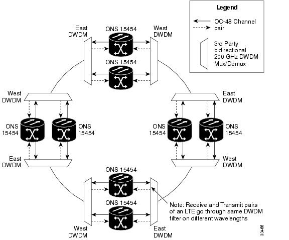
The deployment of DWDM does not limit the type of network topology supported, whether it is a ring, linear, or mesh network. The ability of the ONS 15454 platform to deliver multiple services (DS-1, DS-3, and Ethernet, for example) is unaffected. The DWDM passive multiplexers/demultiplexers are transparent to the data traversing the wavelengths and are used to expand the capacity of the existing fiber. The ONS 15454 can support applications that use both the ITU and standard 1310nm or 1550nm wavelengths depending on the requirements of the particular network. shows the Cisco ONS 15454 used in a DWDM ring application.
Figure 6-2 DWDM Ring Application
6.4.2.1 ONS 15454 DWDM Network Design
The ONS 15454 DWDM solution expands the available options for designing a high-bandwidth network that uses existing infrastructure. It is important to follow a set of engineering guidelines/practices to be sure that you are maximizing the benefits and efficiency of your DWDM network. This section presents high-level examples of some common network design improvements using DWDM.
6.4.2.2 Survivable Network
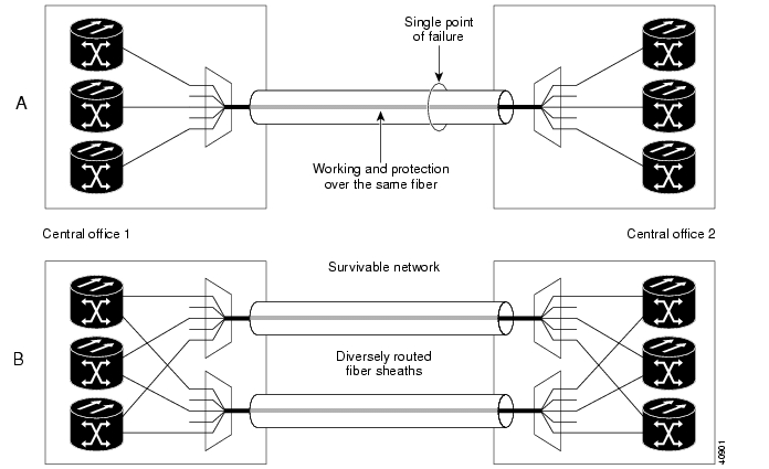
Building a survivable network is one of the primary concerns when making network design decisions. At the very least, you should make sure that there is no interruption of traffic because of a fiber cut. Eliminating a single point of failure is one way to create a more survivable network. shows two examples of the same network. Example A has working and protection circuits set up on the same fiber to create a single point of failure. Example B is a survivable network with working and protection circuits set up on different fibers taking separate routes.
Figure 6-3 Survivable Network
6.4.2.3 Sparing Practices
Sparing keeps a network up and running after a card failure. The two methods of sparing are 1:1 card sparing and wavelength sparing. Wavelength sparing is the preferred method because it requires only one spare card at each site. With 1:1 card sparing, each card must have an identical card in inventory at the site.
![]()
![]()
![]()
![]()
![]()
![]()
![]()
![]()
Posted: Mon Feb 25 07:24:49 PST 2008
All contents are Copyright © 1992--2008 Cisco Systems, Inc. All rights reserved.
Important Notices and Privacy Statement.