|
|

Table Of Contents
8.1 Using the Performance Monitoring Screen
8.1.2 Changing the Screen Intervals
8.1.3 Viewing Near-End and Far-End PMs
8.1.4 Using the Signal-Type Menu
8.1.5 Using the Baseline Button
8.2 Intermediate-Path Performance Monitoring Reference
8.3 Pointer Justification Count Reference
8.4 Performance Monitoring for Electrical Cards
8.4.1 XTC DS1 Performance Monitoring Parameters
8.4.2 XTC DS3 Card Performance Monitoring Parameters
8.5 Performance Monitoring for Optical Cards
8.5.1 OC-3 Card Performance Monitoring Parameters
8.5.2 OC-12 Card Performance Monitoring Parameters
8.5.3 OC-48 Card Performance Monitoring Parameters
Performance Monitoring
Performance-monitoring parameters (PMs) are used by service providers to gather, store, threshold, and report performance data for early detection of problems. In this chapter, PM parameters and concepts are defined for both electrical cards and optical cards.
For information about Ethernet PMs, see Chapter 9, "Ethernet Operation." Additional PM information can also be found under Digital transmission surveillance, in Telcordia's GR-1230-CORE, GR-820-CORE, and GR-253-CORE documents and the ANSI document entitled Digital Hierarchy - Layer 1 In-Service Digital Transmission Performance Monitoring.
Table 8-1 lists PM reference topics.
8.1 Using the Performance Monitoring Screen
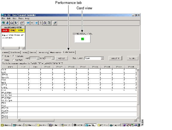
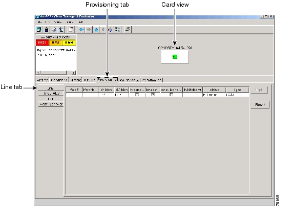
The following sections describe how to use basic screen elements such as tabs, menus, and informational columns. Figure 8-1 shows the Performance tab of Cisco Transport Controller (CTC) card-level view.
Figure 8-1 Viewing performance-monitoring information
8.1.1 Viewing PMs
Before you view PMs, be sure you have created the appropriate circuits and provisioned the card according to your specifications. For information about circuit creation and card provisioning, see "Circuits and Tunnels" and Chapter 7, "Card Provisioning."
Note
Rows relating directly to a card port are always present. Rows relating to an STS or virtual tunnel (VT) carried on the port appear at the time of circuit creation.
Procedure: View PM s
Step 1
Step 2
Step 3
8.1.2 Changing the Screen Intervals
Changing the screen view allows you to view PMs in 15-minute intervals or 24-hour periods. Figure 8-2 shows the time interval buttons on the Performance Monitoring screen. Thirty-three 15-minute periods and two one-day periods of performance monitoring can be displayed. Each period is displayed in one column. The 15-minute periods are anchored to the system clock quarter-hour marks. The one-day periods are anchored to the system clock one-day periods.
Note
Performance-monitoring data for OC-n cards is refreshed on entry to the performance-monitoring pane, or when the signal type is changed. It is not refreshed for Ethernet cards. Data can also refreshed by clicking the Refresh button ( Figure 8-2), or by choosing an auto-refresh time interval.
Note
Note
Figure 8-2 Time interval buttons on the Performance tab (card view)
Procedure: Select Fifteen-Minute PM Intervals on the Performance Monitoring Screen
Step 1
Step 2
Step 3
Step 4
Step 5
Each monitored performance parameter has corresponding threshold values for the current time period. If the value of the counter exceeds the threshold value for a particular 15-minute interval, a threshold crossing alert (TCA) will be raised. The value represents the counter for each specific performance-monitoring parameter.
Note
Step 6
Note
Procedure: Select Twenty-Four Hour PM Intervals on the Performance Monitoring Screen
Step 1
Step 2
Step 3
Step 4
Step 5
Each monitored performance parameter has corresponding threshold values for the current time period. If the value of the counter exceeds the threshold value for a particular 24-hour period, a TCA will be raised. The value represents the counter for each specific performance-monitoring parameter.
Step 6
Note
Procedure: Clearing PM Data on the Performance Monitoring Screen
Step 1
Step 2
•
•
•
Step 3
Step 4
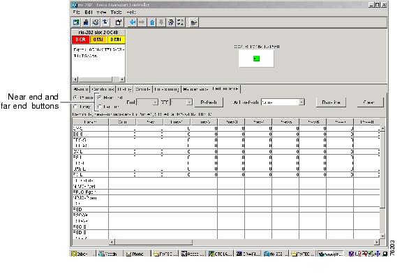
8.1.3 Viewing Near-End and Far-End PMs
Select the Near End or Far End button depending on the PMs you wish to view. Only cards that allow both near-end and far-end monitoring have these buttons as an option. Figure 8-3 shows the Near End and Far End buttons on the Performance Monitoring screen.
Figure 8-3 Near End and Far End buttons on the card view Performance tab
Procedure: Select Near-End PMs on the Performance Monitoring Screen
Step 1
Step 2
Step 3
Step 4
Procedure: Select Far-End PMs on the Performance Monitoring Screen
Step 1
Step 2
Step 3
Step 4
8.1.4 Using the Signal-Type Menu
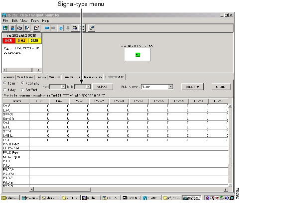
Use the signal-type menus to monitor PMs for near-end or far-end signals on a selected port. Different signal-type menus appear depending on the card type and the circuit type. The appropriate types (DS1, DS3, VT path, STS path, OCn section, line) appear based on the card. For example, the XTC-28-3 has DS3, DS1, VT path, and STS path PMs. Figure 8-4 shows the signal-type menus on the Performance Monitoring screen for an OC48 card.
Figure 8-4 Signal-type menus for an OC48 card
Procedure: Select Signal-Type Menus on the Performance Monitoring Screen
Step 1
Step 2
Step 3
Step 4
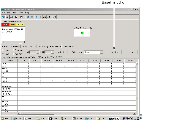
8.1.5 Using the Baseline Button
In Software R3.0 and higher, the Baseline button located on the far right of the screen clears the PM count displayed in the Current column, but does not clear the PM count on the card. The value is changed in the CTC software, but is not changed for the NE. When the current 15-minute or 24-hour time interval expires or the screen view changes, the total number of PM counts on the card and on the screen appear in the appropriate column, decrementing from the values at the time the command is performed.
The baseline values are discarded if you select a new port, interval, near-end, far-end, STS, or if you change views to a different screen and then return to the Performance Monitoring screen. The Baseline button enables you to easily see how quickly PM counts are rising without having to perform calculations. Figure 8-5 shows the Baseline button on the Performance Monitoring screen.
Figure 8-5 Baseline button for clearing displayed PM counts
Procedure: Use the Baseline Button on the Performance Monitoring Screen
Step 1
Step 2
Step 3
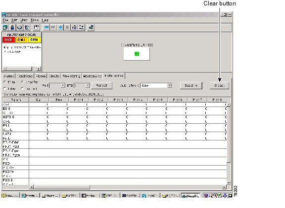
8.1.6 Using the Clear Button
The Clear button located on the far right of the Performance Monitoring screen clears certain PM counts depending on the option selected. Figure 8-6 shows the Clear button on the Performance Monitoring screen.
Caution
Figure 8-6 Clear button for clearing PM counts
Procedure: Use the Clear Button on the Performance Monitoring Screen
Step 1
Step 2
Step 3
Step 4
•
•
•
Step 5
Step 6
Note
Threshold Reference
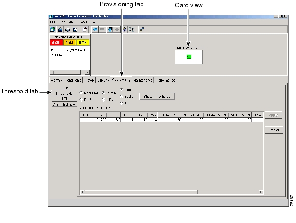
Thresholds are used to set error levels for each PM. You can program PM threshold ranges from the Provisioning > Threshold tabs on the card view. For procedures on provisioning card thresholds, such as line, path, and SONET thresholds, see the Card Provisioning chapter.
During the accumulation cycle, if the current value of a performance monitoring parameter reaches or exceeds its corresponding threshold value, a TCA is generated by the node and sent to CTC. TCAs provide early detection of performance degradation. When a threshold is crossed, the node continues to count the errors during a given accumulation period. If 0 is entered as the threshold value, the performance monitoring parameter is disabled. Figure 8-7 shows the Provisioning > Threshold tabs for an OC-48 card.
Figure 8-7 Threshold tab for setting threshold values
Change the threshold if the default value does not satisfy your error monitoring needs. For example, customers with a critical DS1 installed for 911 calls must guarantee the best quality of service on the line; therefore, they lower all thresholds so that the slightest error raises a TCA.
8.2 Intermediate-Path Performance Monitoring Reference
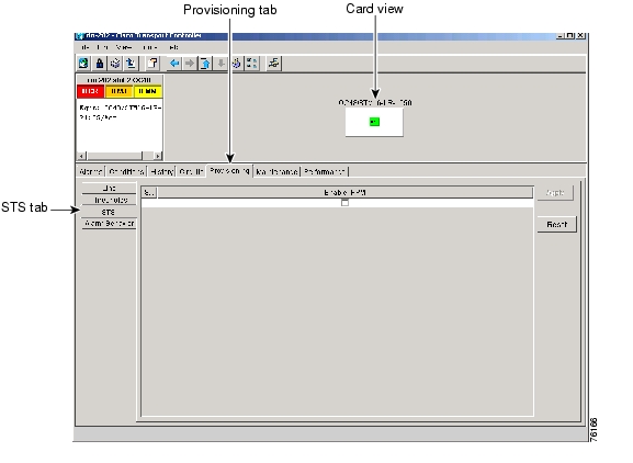
Intermediate-path-performance monitoring (IPPM) allows transparent monitoring of a constituent channel of an incoming transmission signal by a node that does not terminate that channel. In addition to the path-terminating equipment (PTE) on the XTC, such as DS1s and DS3s, an ONS 15327 can terminate optical lines. Table 8-2 shows ONS 15327 cards that are considered LTEs. Figure 8-8 shows the Provisioning > STS tabs for an OC-3 card.
Table 8-2 Traffic Cards That Terminate the Line (LTEs)
OC3 IR 1310
OC48 IR 1310
OC12 IR 1310
OC48 LR 1550
OC12 LR 1550
Figure 8-8 STS tab for enabling IPPM
Software R3.0 and higher allows LTE cards to monitor near-end PM data on individual STS payloads by enabling IPPM. After enabling IPPM provisioning on the line card, service providers can monitor large amounts of STS traffic through intermediate nodes, thus making troubleshooting and maintenance activities more efficient.
IPPM occurs only on STS paths that have IPPM enabled, and TCAs are raised only for PM parameters on the selected IPPM paths. The monitored IPPMs are STS CV-P, STS ES-P, STS SES-P, STS UAS-P, and STS FC-P. For more information about enabling IPPM, see Intermediate-Path Performance Monitoring Reference.
The ONS 15327 performs IPPM by examining the overhead in the monitored path and by reading all of the near-end path PMs in the incoming direction of transmission. The IPPM process allows the path signal to pass bidirectionally through the node completely unaltered.
For detailed information about specific PMs, locate the card name in the following sections and review the appropriate definition.
8.3 Pointer Justification Count Reference
Pointers are used to compensate for frequency and phase variations. Pointer justification counts indicate timing errors on SONET networks. When a network is out of synchronization, signal jitter and signal wander occur on the transported signal. Excessive wander can cause terminating equipment to slip. It also causes slips at the SDH and PDH boundaries.
Slips cause different effects in service. Voice service has intermittent audible clicks. Compressed voice technology has short transmission errors or dropped calls. Fax machines lose scanned lines or experience dropped calls. Digital video transmission has distorted pictures or frozen frames. Encryption service loses the encryption key, causing data to be retransmitted.
Pointers provide a way to align the phase variations in STS and VT payloads. The STS payload pointer is located in the H1 and H2 bytes of the line overhead. Clocking differences are measured by the offset in bytes from the pointer to the first byte of the STS synchronous payload envelope (SPE) called the J1 byte. Clocking differences that exceed the normal range of 0 to 782 can cause data loss.
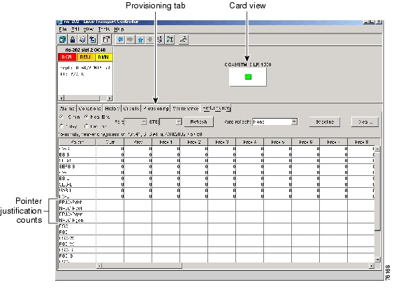
Figure 8-9 shows pointer justification count parameters on the Performance Monitoring screen. You can enable PPJC and NPJC performance monitoring parameters for LTE cards. See Table 8-2 for a list of Cisco ONS 15327 LTE cards.
Figure 8-9 Viewing pointer justification count parameters
There are positive (PPJC) and negative (NPJC) pointer justification count parameters. PPJC is a count of path-detected (PPJC-Pdet) or path-generated (PPJC-Pgen) positive pointer justifications. NPJC is a count of path-detected (NPJC-Pdet) or path-generated (NPJC-Pgen) negative pointer justifications depending on the specific PM name.
A consistent pointer justification count indicates clock synchronization problems between nodes. A difference between the counts means the node transmitting the original pointer justification has timing variations with the node detecting and transmitting this count. Positive pointer adjustments occur when the frame rate of the SPE is too slow in relation to the rate of the STS 1.
For pointer justification count definitions, depending on the cards in use, see the "OC-3 Card Performance Monitoring Parameters" section, "OC-12 Card Performance Monitoring Parameters" section, or the "OC-48 Card Performance Monitoring Parameters" section.
On CTC, the count fields for PPJC and NPJC PMs appear white and blank unless they are enabled on the Provisioning > Line tabs. Figure 8-10 shows the PJStsMon# menu on the Provisioning screen. Pointer justification is only enabled for one STS at a time.
Figure 8-10 Line tab for enabling pointer justification count parameters
8.4 Performance Monitoring for Electrical Cards
The following sections define performance monitoring parameters for the XTC DS1 and XTC DS3 electrical cards.
8.4.1 XTC DS1 Performance Monitoring Parameters
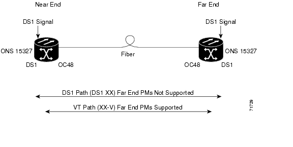
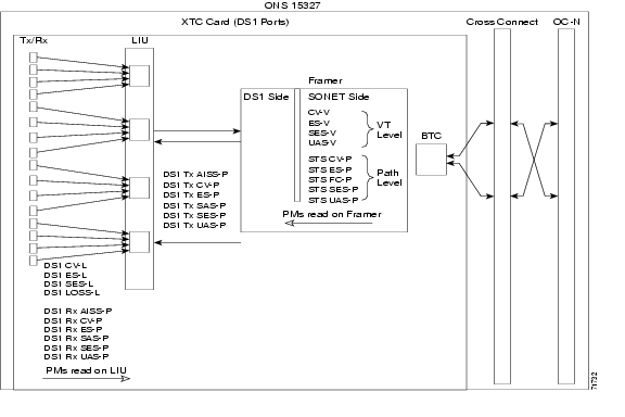
Figure 8-11 shows the signal types that support far-end PMs. Far-end VT and STS path-performance monitoring is supported for the DS1 card. Far-end DS1 path-performance monitoring is not supported for the DS1 card. Figure 8-12 shows where overhead bytes detected on the ASICs produce performance monitoring parameters for the DS1 cards.
Figure 8-11 Monitored signal types for the XTC DS1 cards
Note
Figure 8-12 PM read points on the XTC DS1 cards
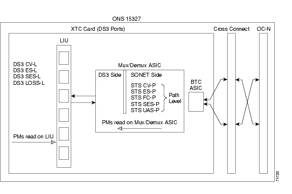
8.4.2 XTC DS3 Card Performance Monitoring Parameters
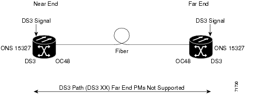
Figure 8-13 shows the signal types that support far-end PMs. Figure 8-14 shows where overhead bytes detected on the ASICs produce performance monitoring parameters for the XTC DS3 cards.
Figure 8-13 Monitored signal types for the XTC DS3 cards
Note
Figure 8-14 PM read points on the XTC DS3 cards
8.5 Performance Monitoring for Optical Cards
The following sections define performance monitoring parameters and definitions for the OC-3, OC-12, and OC-48 cards.
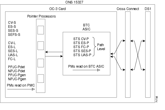
8.5.1 OC-3 Card Performance Monitoring Parameters
Figure 8-15 shows where overhead bytes detected on the ASICs produce performance monitoring parameters for the OC-3 card.
Figure 8-15 PM read points on the OC-3 card
Note
Table 8-13 Near-End Protection-Switching PMs for the OC-3 Cards
For information about Troubleshooting UPSR switch counts, see the alarm troubleshooting information in Chapter 14, "Alarm Troubleshooting". For information about creating circuits that perform a switch, see "Circuits and Tunnels."
In a 1+1 protection scheme for a working card, Protection Switching Count (PSC) is a count of the number of times service switches from a working card to a protection card plus the number of times service switches back to the working card.
For a protection card, PSC is a count of the number of times service switches to a working card from a protection card plus the number of times service switches back to the protection card. The PSC PM is only applicable if revertive line-level protection switching is used.
Note
Protection Switching Duration (PSD) applies to the length of time, in seconds, that service is carried on another line. For a working line, PSD is a count of the number of seconds that service was carried on the protection line.
For the protection line, PSD is a count of the seconds that the line was used to carry service. The PSD PM is only applicable if revertive line-level protection switching is used.
Note
Table 8-14 Near-End SONET Path H-Byte PMs for the OC-3 Card
Note
Positive Pointer Justification Count path-detected (PPJC-Pdet) is a count of the positive pointer justifications detected on a particular path on an incoming SONET signal.
Negative Pointer Justification Count path-detected (NPJC-Pdet) is a count of the negative pointer justifications detected on a particular path on an incoming SONET signal.
Positive Pointer Justification Count path-generated (PPJC-Pgen) is a count of the positive pointer justifications generated for a particular path to reconcile the frequency of the SPE with the local clock.
Negative Pointer Justification Count path-generated (NPJC-Pgen) is a count of the negative pointer justifications generated for a particular path to reconcile the frequency of the SPE with the local clock.
Table 8-15 Near-End SONET Path PMs for the OC-3 Card
Note
Near-End STS Path Coding Violations (STS CV-P) is a count of B IP errors detected at the STS path layer (i.e., using the B3 byte). Up to eight B IP errors can be detected per frame; each error increments the current CV-P second register.
Near-End STS Path Errored Seconds (STS ES-P) is a count of the seconds when one or more STS path B IP errors were detected. An AIS-P defect (or a lower-layer, traffic-related, near-end defect) or an LOP-P defect can also cause an STS ES-P.
Near-End STS Path Failure Counts (STS FC-P) is a count of the number of near-end STS path failure events. A failure event begins with an AIS-P failure, an LOP-P failure, a UNEQ-P failure, or a TIM-P failure is declared, or if the STS PTE that is monitoring the path supports ERDI-P for that path. The failure event ends when these failures are cleared.
Near-End STS Path Severely Errored Seconds (STS SES-P) is a count of the seconds when K (2400) or more STS path B IP errors were detected. An AIS-P defect (or a lower-layer, traffic-related, near-end defect) or an LOP-P defect can also cause an STS Severely Errored Seconds Path (SES-P).
Near-End STS Path Unavailable Seconds (STS UAS-P) is a count of the seconds when the STS path is considered unavailable. An STS path becomes unavailable at the onset of ten consecutive seconds that qualify as Severely Errored Seconds Path (SES-Ps), and continues to be unavailable until the onset of ten consecutive seconds that do not qualify as SES-Ps.
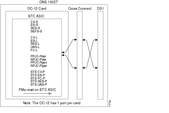
8.5.2 OC-12 Card Performance Monitoring Parameters
Figure 8-16 shows the signal types that support far-end PMs. Figure 8-17 shows where overhead bytes detected on the ASICs produce performance monitoring parameters for the OC-12 card.
Figure 8-16 Monitored signal types for the OC-12 card
Note
Figure 8-17 PM read points on the OC-12 card
Note
Table 8-19 Near-End SONET Path H-byte PMs for the OC-12 Card
Note
Positive Pointer Justification Count path-detected (PPJC-Pdet) is a count of the positive pointer justifications detected on a particular path on an incoming SONET signal.
Negative Pointer Justification Count path-detected (NPJC-Pdet) is a count of the negative pointer justifications detected on a particular path on an incoming SONET signal.
Positive Pointer Justification Count path-generated (PPJC-Pgen) is a count of the positive pointer justifications generated for a particular path to reconcile the frequency of the SPE with the local clock.
Negative Pointer Justification Count path-generated (NPJC-Pgen) is a count of the negative pointer justifications generated for a particular path to reconcile the frequency of the SPE with the local clock.
Table 8-20 Near-End Protection-Switching PMs for the OC-12 Card
For information about Troubleshooting UPSR switch counts, see Chapter 14, "Alarm Troubleshooting." For information about creating circuits that perform a switch, see "Circuits and Tunnels."
For a protect line in a 2-fiber ring, Protection Switching Count (PSC) refers to the number of times a protection switch has occurred either to a particular span's line protection or away from a particular span's line protection. Therefore, if a protection switch occurs on a 2-fiber BLSR, the PSC of the protection span to which the traffic is switched will increment, and when the switched traffic returns to its original working span from the protect span, the PSC of the protect span will increment again.
Note
In a 1+1 protection scheme for a working card, Protection Switching Count (PSC) is a count of the number of times service switches from a working card to a protection card plus the number of times service switches back to the working card.
For a protection card, PSC is a count of the number of times service switches to a working card from a protection card plus the number of times service switches back to the protection card. The PSC PM is only applicable if revertive line-level protection switching is used.
For an active protection line in a 2-fiber BLSR, Protection Switching Duration (PSD) is a count of the number of seconds that the protect line is carrying working traffic following the failure of the working line. PSD increments on the active protect line and Protection Switching Duration-Working (PSD-W) increments on the failed working line.
Note
For a working line in a 2-fiber BLSR, Protection Switching Count-Working (PSC-W) is a count of the number of times traffic switches away from the working capacity in the failed line and back to the working capacity after the failure is cleared. PSC-W increments on the failed working line and PSC increments on the active protect line.
For a working line in a 2-fiber BLSR, Protection Switching Duration-Working (PSD-W) is a count of the number of seconds that service was carried on the protection line. PSD-W increments on the failed working line and PSD increments on the active protect line.
Table 8-21 Near-End Protection-Switching Path PMs for the OC-12 Card
Note
Near-End STS Path Coding Violations (STS CV-P) is a count of B IP errors detected at the STS path layer (i.e., using the B3 byte). Up to eight B IP errors can be detected per frame; each error increments the current CV-P second register.
Near-End STS Path Errored Seconds (STS ES-P) is a count of the seconds when at least one STS path B IP error was detected. An AIS-P defect (or a lower-layer, traffic-related, near-end defect) or an LOP-P defect can also cause an STS ES-P.
Near-End STS Path Failure Counts (STS FC-P) is a count of the number of near-end STS path failure events. A failure event begins with an AIS-P failure, an LOP-P failure, a UNEQ-P failure or a TIM-P failure is declared, or if the STS PTE that is monitoring the path supports ERDI-P for that path. The failure event ends when these failures are cleared.
Near-End STS Path Severely Errored Seconds (STS SES-P) is a count of the seconds when K (2400) or more STS path B IP errors were detected. An AIS-P defect (or a lower-layer, traffic-related, near-end defect) or an LOP-P defect can also cause an STS Severely Errored Seconds Path (SES-P).
Near-End STS Path Unavailable Seconds (STS UAS-P) is a count of one-second intervals when the STS path is unavailable. An STS path is unavailable at the onset of ten consecutive seconds that qualify as Severely Errored Seconds Path (SES-Ps), and continues to be unavailable until the onset of ten consecutive seconds occur that do not qualify as SES-Ps. The ten seconds with no SES-Ps are excluded from unavailable time.
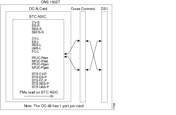
8.5.3 OC-48 Card Performance Monitoring Parameters
Figure 8-18 shows the signal types that support far-end PMs. Figure 8-19 shows where overhead bytes detected on the ASICs produce performance monitoring parameters for the OC-48 cards.
Figure 8-18 Monitored signal types for the OC-48 cards
Note
Figure 8-19 PM read points on the OC-48 cards
Note
Table 8-25 Near-End SONET Path H-byte PMs for the OC-48 Cards
Note
Positive Pointer Justification Count path-detected (PPJC-Pdet) is a count of the positive pointer justifications detected on a particular path on an incoming SONET signal.
Negative Pointer Justification Count path-detected (NPJC-Pdet) is a count of the negative pointer justifications detected on a particular path on an incoming SONET signal.
Positive Pointer Justification Count path-generated (PPJC-Pgen) is a count of the positive pointer justifications generated for a particular path to reconcile the frequency of the SPE with the local clock.
Negative Pointer Justification Count path-generated (NPJC-Pgen) is a count of the negative pointer justifications generated for a particular path to reconcile the frequency of the SPE with the local clock.
Table 8-26 Near-End Protection-Switching PMs for the OC-48 Cards
For information about Troubleshooting UPSR switch counts, see Chapter 14, "Alarm Troubleshooting." For information about creating circuits that perform a switch, see "Circuits and Tunnels."
For a protect line in a 2-fiber ring, Protection Switching Count (PSC) refers to the number of times a protection switch has occurred either to a particular span's line protection or away from a particular span's line protection. Therefore, if a protection switch occurs on a 2-fiber BLSR, the PSC of the protection span to which the traffic is switched will increment, and when the switched traffic returns to its original working span from the protect span, the PSC of the protect span will increment again.
In a 1+1 protection scheme for a working card, PSC is a count of the number of times service switches from a working card to a protection card plus the number of times service switches back to the working card.
For a protection card, PSC is a count of the number of times service switches to a working card from a protection card plus the number of times service switches back to the protection card. The PSC PM is only applicable if revertive line-level protection switching is used.
For an active protection line in a 2-fiber BLSR, Protection Switching Duration (PSD) is a count of the number of seconds that the protect line is carrying working traffic following the failure of the working line. PSD increments on the active protect line and Protection Switching Duration-Working (PSD-W) increments on the failed working line.
For a working line in a 2-fiber BLSR, PSC-W is a count of the number of times traffic switches away from the working capacity in the failed line and back to the working capacity after the failure is cleared. PSC-W increments on the failed working line and PSC increments on the active protect line.
For a working line in a 2-fiber BLSR, PSD-W is a count of the number of seconds that service was carried on the protection line. Protection Switching Duration-Working (PSD-W) increments on the failed working line and PSD increments on the active protect line.
Table 8-27 Near-End SONET Path PMs for the OC-48 Cards
Note
Near-End STS Path Coding Violations (STS CV-P) is a count of B IP errors detected at the STS path layer (i.e., using the B3 byte). Up to eight B IP errors can be detected per frame; each error increments the current CV-P second register.
Near-End STS Path Errored Seconds (STS ES-P) is a count of the seconds when at least one STS path B IP error was detected. An AIS-P defect (or a lower-layer, traffic-related, near-end defect) or an LOP-P defect can also cause an STS ES-P.
Near-End STS Path Failure Counts (STS FC-P) is a count of the number of near-end STS path failure events. A failure event begins with an AIS-P failure, an LOP-P failure, a UNEQ-P failure or a TIM-P failure is declared, or if the STS PTE that is monitoring the path supports ERDI-P for that path. The failure event ends when these failures are cleared.
Near-End STS Path Severely Errored Seconds (STS SES-P) is a count of the seconds when K (2400) or more STS path B IP errors were detected. An AIS-P defect (or a lower-layer, traffic-related, near-end defect) or an LOP-P defect can also cause an STS Severely Errored Seconds Path (SES-P).
Near-End STS Path Unavailable Seconds (STS UAS-P) is a count of the one-second intervals when the STS path is unavailable. The STS path is unavailable at the onset of ten consecutive seconds that qualify as Severely Errored Seconds Path (SES-Ps), and continues to be unavailable until the onset of ten consecutive seconds that do not qualify as SES-Ps. The ten seconds with no SES-Ps are excluded from available time.
![]()
![]()
![]()
![]()
![]()
![]()
![]()
![]()
Posted: Mon Feb 25 06:03:00 PST 2008
All contents are Copyright © 1992--2008 Cisco Systems, Inc. All rights reserved.
Important Notices and Privacy Statement.