|
|

Table Of Contents
9.1 Ethernet over SONET Application
9.2.1 E10/100-4 Card Port Provisioning
9.3 Multicard and Single-Card EtherSwitch
9.3.3 ONS 15454 E Series and ONS 15327 EtherSwitch Circuit Combinations
9.4 Ethernet Circuit Configurations
9.4.1 Point-to-Point Ethernet Circuits
9.4.2 Shared Packet Ring Ethernet Circuits
9.4.3 Hub and Spoke Ethernet Circuit Provisioning
9.4.4 Ethernet Manual Cross-Connects
9.5.2 Priority Queuing (IEEE 802.1Q)
9.6 Spanning Tree (IEEE 802.1D)
9.6.1 Multi-Instance Spanning Tree and VLANs
9.6.2 Spanning-Tree Parameters
9.6.3 Spanning-Tree Configuration
9.6.5 Ethernet Performance Screen
9.6.6 Ethernet Maintenance Screen
9.7 Remote Monitoring Specification Alarm Thresholds
Ethernet Operation
This chapter explains how to use the Ethernet features of the Cisco ONS 15327, including transporting ONS 15327 Ethernet data over SONET, creating and provisioning VLANs, protecting Ethernet traffic with Spanning Tree Protocol (STP), provisioning Multicard and Single-card EtherSwitch, provisioning several types of Ethernet circuits, viewing Ethernet performance data stored in CTC, creating Ethernet Remote Monitoring (RMON) alarm thresholds, and troubleshooting Ethernet connections.
9.1 Ethernet over SONET Application
The ONS 15327 integrates Ethernet access into the same SONET platform that transports voice traffic. Ethernet over SONET lets service providers augment time division multiplexing (TDM) services with Ethernet, and allows users to deliver data traffic over existing facilities. The ONS 15327 supports layer 2 switching and the ability to classify Ethernet traffic as defined in the IEEE 802.1Q standard. You can switch tagged traffic onto separate SONET STS channels to allocate bandwidth by traffic class.The ONS 15327 can also concentrate Ethernet ports into one or more STS-N circuits to use bandwidth more efficiently.
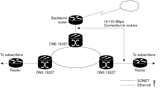
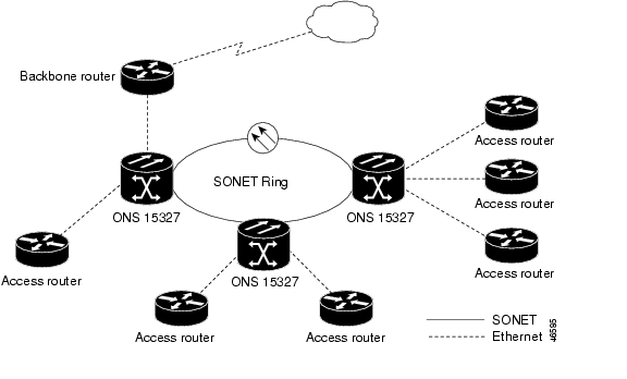
The ONS 15327 Ethernet solution uses existing SONET infrastructure to transport aggregate (combined) traffic from multiple, remote sources. Figure 9-1 illustrates aggregation and transport.
Figure 9-1 Ethernet transporting aggregate traffic from multiple sources
9.2 ONS 15327 Ethernet Card
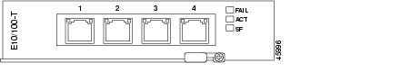
The ONS 15327 uses the E10/100-4 Ethernet card to provide Ethernet interfaces. Figure 9-2 shows the E10/100-4 Ethernet card faceplate. For a detailed description of the E10/100-4 card, refer to Chapter 13, "Card Reference."
Figure 9-2 E10/100-4 Ethernet card faceplate
The E10/E100-4 has a bi-color LED on both sides of each of the four RJ-45 connectors. Each pair of LEDs shows the port's state. LED states are listed in Table 9-1.
Table 9-1 E10/1004 faceplate LEDs
Green and Amber
Transmitting/Receiving
Green and Off
Idle and Link Integrity
The ONS 15327 uses E10/100-4 cards for Ethernet (10 Mbps) and Fast Ethernet (100 Mbps). The E10/100-4 enables network operators to provide multiple 10/100-Mbps access drops for high-capacity customer LAN interconnections. The card provides efficient transport and coexistence of traditional TDM traffic with packet-switched data traffic. The E10/100-4 helps eliminate the need for external Ethernet aggregation equipment.
E10/100-4 specifications:
•
Operating temperature: 32 to 131 degrees Farenheit (0 to +55 degrees Celsius)
•
•
9.2.1 E10/100-4 Card Port Provisioning
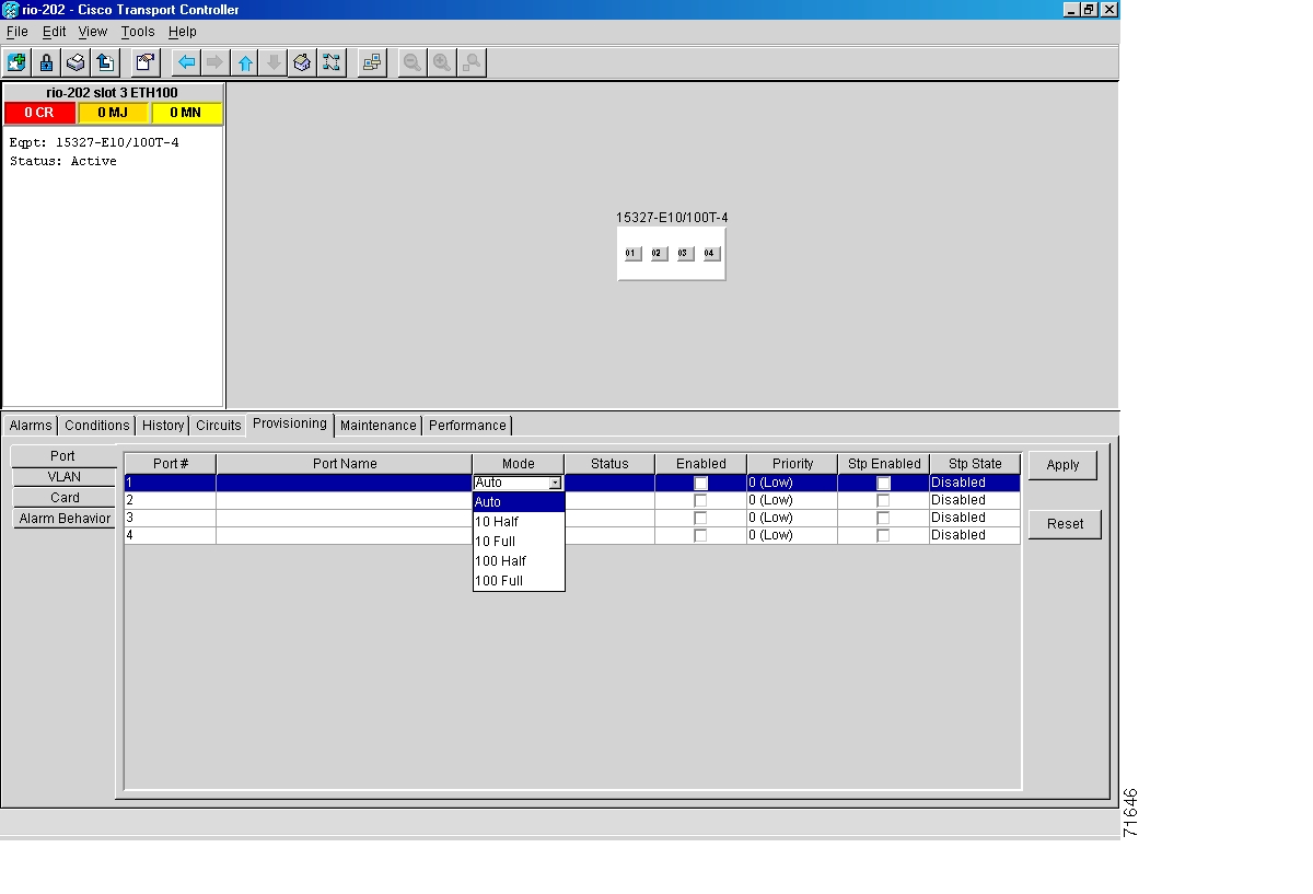
This section explains how to provision Ethernet ports on an E10/100-4 Ethernet card. Most provisioning requires you to fill in two fields: Enabled and Mode. However, you can also map incoming traffic to a low priority or a high priority queue using the Priority column, and you can enable spanning tree with the Stp Enabled column. For more information about spanning tree, see the "Spanning Tree (IEEE 802.1D)" section. The Status column displays information about the port's current operating mode, and the Stp State column provides the current spanning tree status.
Procedure: Provision E10/100-4 Ethernet Ports
Step 1
Figure 9-3 Provisioning E10/100-4 Ethernet ports
Step 2
Step 3
Step 4
Your Ethernet ports are now provisioned and ready to be configured for VLAN membership.
Step 5
9.3 Multicard and Single-Card EtherSwitch
The ONS 15327 enables Multicard and Single-card EtherSwitch modes. At the Ethernet card view in CTC, click the Provisioning > Card tabs to reveal the Card Mode option.
9.3.1 Multicard EtherSwitch
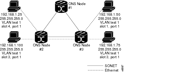
Multicard EtherSwitch provisions two or more Ethernet cards to act as a single layer 2 switch. It supports one STS-3c circuit or three STS-1 shared packet rings. The bandwidth of the single switch formed by the Ethernet cards matches the bandwidth of the provisioned Ethernet circuit up to STS-3c worth of bandwidth. Figure 9-4 illustrates a Multicard EtherSwitch configuration.
Figure 9-4 A Multicard EtherSwitch configuration
9.3.2 Single-Card EtherSwitch
Single-card EtherSwitch allows each Ethernet card to remain a single switching entity within the ONS 15327 shelf. This option allows a full STS-12c worth of bandwidth between two Ethernet circuit points. Figure 9-5 illustrates a Single-card EtherSwitch configuration.
Figure 9-5 A Single-card EtherSwitch configuration
Seven scenarios exist for provisioning Single-card EtherSwitch bandwidth:
1.
2.
3.
4.
5.
6.
7.
Note
9.3.3 ONS 15454 E Series and ONS 15327 EtherSwitch Circuit Combinations
Table 9-2 shows the Ethernet circuit combinations available in the ONS 15327 E10/100-4 cards and ONS 15454 E series cards.
9.4 Ethernet Circuit Configurations
Ethernet circuits can link ONS nodes through point-to-point, shared packet ring, or hub and spoke configurations. Two nodes usually connect with a point-to-point configuration. More than two nodes usually connect with a shared packet ring configuration or a hub and spoke configuration. This section includes procedures for creating these configurations and also explains how to create Ethernet manual cross-connects. Ethernet manual cross-connects allow you to cross connect individual Ethernet circuits to an STS channel on the ONS 15327 optical interface and also to bridge non-ONS SONET network segments.
Note
Note
9.4.1 Point-to-Point Ethernet Circuits
The ONS 15327 can set up a point-to-point (straight) Ethernet circuit as Single-card or Multicard. Multicard EtherSwitch limits bandwidth to STS-3c of bandwidth between two Ethernet circuit points, but allows you to add nodes and cards and make a shared packet ring. Single-card EtherSwitch allows a full STS-12c of bandwidth between two Ethernet circuit points. Figure 9-6 shows a Multicard EtherSwitch point-to-point circuit. Figure 9-7 shows a Single-card EtherSwitch point-to-point circuit.
Figure 9-6 Multicard EtherSwitch point-to-point circuit
Figure 9-7 Single-card EtherSwitch point-to-point circuit
Procedure: Provision an EtherSwitch Point-to-Point Circuit (Multicard or Single-Card)
Step 1
Step 2
Step 3
Step 4
a.
b.
c.
If you are building a Single-card EtherSwitch circuit:
a.
b.
Step 5
Step 6
Step 7
The Circuit Creation (Circuit Attributes) dialog box appears.
Step 8
Step 9
Note
Step 10
The valid circuit sizes for an Ethernet Multicard circuit are STS-1 and STS-3c.
The valid circuit sizes for an Ethernet Single-card circuit are STS-1, STS-3c, STS-6c and STS-12c.
Step 11
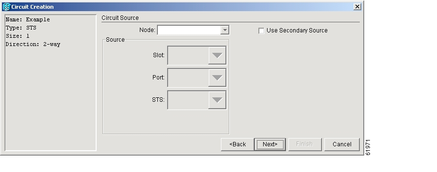
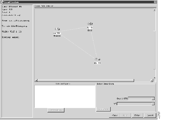
The Circuit Creation (Circuit Source) dialog box appears ( Figure 9-8).
Figure 9-8 Choosing a circuit source
Step 12
Step 13
Step 14
The Circuit Creation (Destination) dialog box opens.
Step 15
Step 16
Step 17
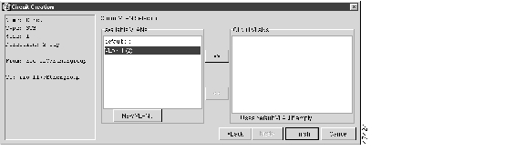
The Circuit Creation (Circuit VLAN Selection) dialog box appears.
Step 18
a.
b.
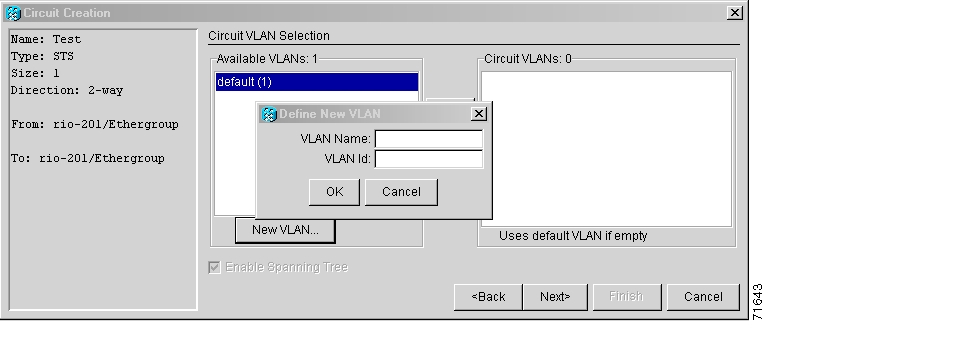
Figure 9-9 Choosing a VLAN name and ID
c.
Note
d.
e.
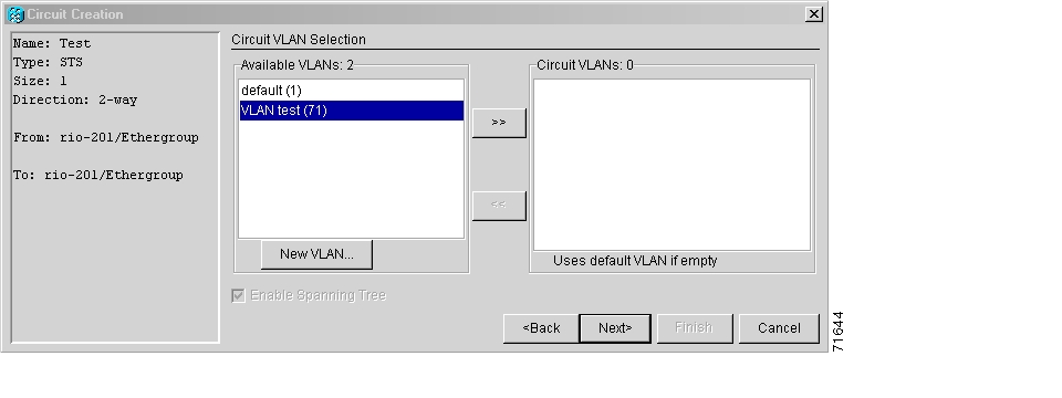
Figure 9-10 Selecting VLANs
Step 19
The Circuit Creation (Circuit Routing Preferences) dialog box appears.
Step 20
•
•
•
•
•
Step 21
Step 22
9.4.2 Shared Packet Ring Ethernet Circuits
This section provides steps for creating a shared packet ring ( Figure 9-11). Your network architecture may differ from the example.
Figure 9-11 Shared packet ring Ethernet circuit
Procedure: Provision a Shared Packet Ring
Step 1
Step 2
Step 3
Step 4
Step 5
Step 6
Step 7
Step 8
Step 9
Step 10
The Circuit Creation (Circuit Attributes) dialog box appears.
Step 11
Step 12
Note
Step 13
For shared packet ring Ethernet, valid circuit sizes are STS-1 and STS-3c.
Step 14
Note
Step 15
The Circuit Creation (Circuit Source) dialog box appears.
Step 16
Any shared packet ring node can serve as the circuit source.
Step 17
The Circuit Creation (Circuit Destination) dialog box appears
Step 18
Step 19
Step 20
The Circuit Creation (Circuit VLAN Selection) dialog box appears.
Step 21
a.
The Circuit Creation (Define New VLAN) dialog box appears ( Figure 9-9).
b.
c.
This VLAN ID number must be unique. It is usually the next available number not already assigned to an existing VLAN (between 2 and 4093). Each ONS 15327 network supports a maximum of 509 user-provisionable VLANs.
d.
e.
By moving the VLAN from the Available VLANs column to the Circuit VLANs column, all the VLAN traffic is forced to use the shared packet ring circuit you created.
Step 22
Step 23
Step 24
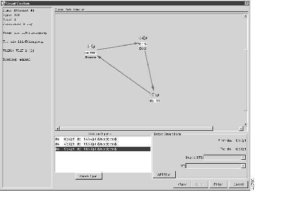
The span turns white.
Figure 9-12 Adding a span
Step 25
The span turns blue and the span is added to the Included Spans field.
Step 26
Step 27
The span turns white.
Step 28
The span turns blue.
Step 29
Figure 9-13 Viewing a span
Step 30
Note
Step 31
Step 32
9.4.3 Hub and Spoke Ethernet Circuit Provisioning
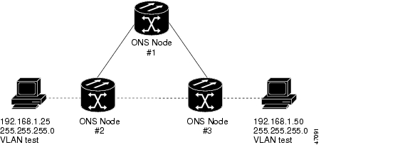
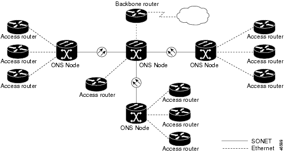
This section provides steps for creating a hub and spoke Ethernet circuit configuration. The hub and spoke configuration connects point-to-point circuits (the spokes) to an aggregation point (the hub). In many cases, the hub links to a high-speed connection and the spokes are Ethernet cards. Figure 9-14 illustrates a sample hub and spoke ring. Your network architecture may differ from the example.
Figure 9-14 A Hub and spoke Ethernet circuit
Procedure: Provision a Hub and Spoke Ethernet Circuit
Step 1
Step 2
Step 3
Step 4
If Single-card EtherSwitch is not checked, check it and click Apply.
Step 5
Step 6
Step 7
The Circuit Creation (Circuit Attributes) dialog box appears.
Step 8
Step 9
Note
Step 10
Step 11
The Circuit Creation (Circuit Source) dialog box appears.
Step 12
Either end node can be the circuit source.
Step 13
The Circuit Creation (Circuit Destination) dialog box appears.
Step 14
Choose the node that is not the source.
Step 15
The Circuit Creation (Circuit VLAN Selection) dialog box appears ( Figure 9-8).
Step 16
a.
The Circuit Creation (Define New VLAN) dialog box appears ( Figure 9-10).
b.
c.
This should be the next available number (between 2 and 4093) not already assigned to an existing VLAN. Each ONS 15327 network supports a maximum of 509 user-provisionable VLANs.
d.
e.
Step 17
The Circuit Creation (Circuit Routing Preferences) dialog box appears.
Step 18
•
•
•
•
•
Note
Step 19
Step 20
Step 21
Step 22
Step 23
If the Single-card EtherSwitch check box is not checked, check it and click Apply.
Step 24
Step 25
Step 26
Step 27
Note
Step 28
Step 29
Step 30
Either end node can be the circuit source.
Step 31
Choose the node that is not the source.
Step 32
The Circuit Creation (Circuit VLAN Selection) dialog box appears.
Step 33
Step 34
Step 35
9.4.4 Ethernet Manual Cross-Connects
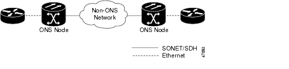
ONS 15327s require end-to-end CTC visibility between nodes for normal provisioning of Ethernet circuits. When other vendors' equipment sits between ONS 15327s, OSI/TARP-based equipment does not allow tunneling of the ONS 15327 TCP/IP-based DCC. To circumvent this lack of continuous DCC, the Ethernet circuit must be manually cross connected to an STS channel riding through the non-ONS network. This allows an Ethernet circuit to run from ONS node to ONS node utilizing the non-ONS network.
Note
Figure 9-15 Ethernet manual cross-connects
Procedure: Provision a Single-card EtherSwitch Manual Cross-Connect
Step 1
Step 2
Step 3
Step 4
If the Single-card EtherSwitch is not checked, check it and click Apply.
Step 5
Step 6
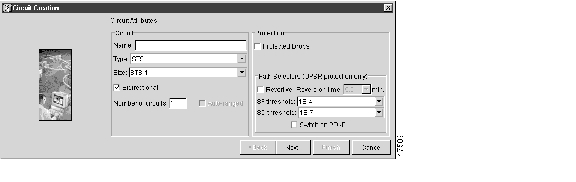
The Circuit Creation (Circuit Attributes) dialog box appears ( Figure 9-16).
Figure 9-16 Creating an Ethernet circuit
Step 7
Step 8
Note
Step 9
The valid circuit sizes for an Ethernet Single-card circuit are STS-1, STS-3c, STS-6c and 12c.
Step 10
The Circuit Creation (Circuit Source) dialog box appears.
Step 11
Step 12
The Circuit Creation (Circuit Destination) dialog box appears.
Step 13
Step 14
Step 15
Note
The Circuit Creation (Circuit VLAN Selection) dialog box appears ( Figure 9-10).
Step 16
a.
The Circuit Creation (Define New VLAN) dialog box appears ( Figure 9-10).
b.
c.
The VLAN ID should be the next available number (between 2 and 4093) that is not already assigned to an existing VLAN. Each ONS 15327 network supports a maximum of 509 user-provisionable VLANs.
d.
e.
Figure 9-17 Selecting VLANs
Step 17
The Circuit Creation (Circuit Routing Preferences) dialog box appears.
Step 18
•
•
•
•
•
Note
Step 19
Step 20
Step 21
Note
Caution
Procedure: Provision a Multicard EtherSwitch Manual Cross-Connect
Step 1
Step 2
Step 3
Step 4
If the Multi-card EtherSwitch Group is not checked, check it and click Apply.
Step 5
Step 6
Step 7
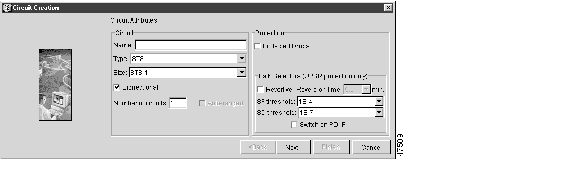
The Circuit Creation (Circuit Attributes) dialog box appears ( Figure 9-18).
Figure 9-18 Creating an Ethernet circuit
Step 8
Step 9
Note
Step 10
The valid circuit sizes for an Ethernet Multicard circuit are STS-1 and STS-3c.
Step 11
The Circuit Creation (Circuit Source) dialog box appears.
Step 12
Step 13
The Circuit Creation (Circuit Destination) dialog box appears.
Step 14
Step 15
Note
The Circuit Creation (Circuit VLAN Selection) dialog box appears ( Figure 9-10).
Step 16
a.
The Circuit Creation (Define New VLAN) dialog box opens ( Figure 9-9).
b.
c.
The VLAN ID should be the next available number (between 2 and 4093) that is not already assigned to an existing VLAN. Each ONS 15327 network supports a maximum of 509 user-provisionable VLANs.
d.
e.
Figure 9-19 Selecting VLANs
Step 17
The Circuit Creation (Circuit Routing Preferences) dialog box appears.
Step 18
•
•
•
•
•
Note
Step 19
You now need to provision the Ethernet ports and assign ports to VLANs. For port provisioning instructions, see the "Provision E10/100-4 Ethernet Ports" procedure. For information about assigning ports to VLANs, see the "Provision Ethernet Ports for VLAN Membership" procedure. Return to Step 20 after assigning the ports to VLANs.
Step 20
The Edit Circuit dialog box appears.
Step 21
The Define New Drop dialog box appears.
Step 22
Step 23
Step 24
Step 25
The Edit Circuit dialog box appears.
Step 26
Step 27
Note
Caution
9.5 VLAN Support
Users can provision up to 509 VLANs with the CTC software. Specific sets of ports define the broadcast domain for the ONS 15327. The definition of VLAN ports includes all Ethernet and packet-switched SONET port types. All VLAN IP address discovery, flooding, and forwarding is limited to these ports.
The ONS 15327 IEEE 802.1Q-based VLAN mechanism provides logical isolation of subscriber LAN traffic over a common SONET transport infrastructure. Each subscriber has an Ethernet port at each site, and each subscriber is assigned to a VLAN. Although the subscriber's VLAN data flows over shared circuits, the service appears to the subscriber as a private data transport.
9.5.1 Q-Tagging (IEEE 802.1Q)
IEEE 802.1Q allows the same physical port to host multiple IEEE 802.1Q VLANs. Each IEEE 802.1Q VLAN represents a different logical network.
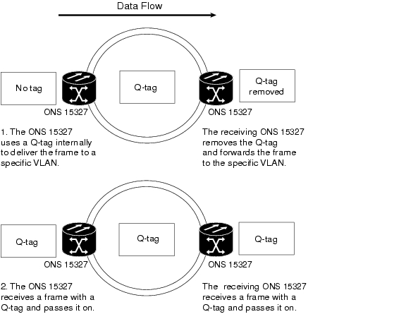
The ONS 15327 works with Ethernet devices that support IEEE 802.1Q and those that do not support IEEE 802.1Q. If a device attached to an ONS 15327 Ethernet port does not support IEEE 802.1Q, the ONS 15327 only uses Q-tags internally. The ONS 15327 associates these Q-tags with specific ports.
With Ethernet devices that do not support IEEE 802.1Q, the ONS 15327 takes non-tagged Ethernet frames that enter the ONS network and uses a Q-tag to assign the packet to the VLAN associated with the ingress port of the ONS network. The receiving ONS node removes the Q-tag when the frame leaves the ONS network (to prevent older Ethernet equipment from incorrectly identifying the IEEE 8021.Q packet as an illegal frame). The ingress and egress ports on the ONS network must be set to Untag for the process to occur. Untag is the default setting for ONS ports. Example 1 in Figure 9-20 illustrates Q-tag use only within an ONS network.
With Ethernet devices that support IEEE 802.1Q, the ONS 15327 uses the Q-tag attached by the external Ethernet devices. Packets enter the ONS network with an existing Q-tag; the ONS 15327 uses this same Q-tag to forward the packet within the ONS network and leaves the Q-tag attached when the packet leaves the ONS network. Set both entry and egress ports on the ONS network to Tagged for this process to occur. Example 2 in Figure 9-20 illustrates the handling of packets that both enter and exit the ONS network with a Q-tag.
For more information about setting ports to Tagged and Untag, see the "Provision Ethernet Ports for VLAN Membership" procedure.
Figure 9-20 A Q-tag moving through a VLAN
9.5.2 Priority Queuing (IEEE 802.1Q)
Note
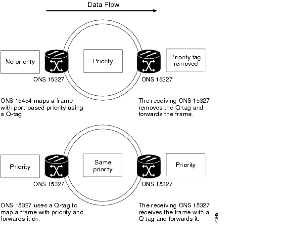
Networks without priority queuing handle all packets on a first-in, first-out (FIFO) basis. Priority queuing reduces the impact of network congestion by mapping Ethernet traffic to different priority levels. The ONS 15327 supports priority queuing. The ONS 15327 takes the eight priorities specified in IEEE 802.1Q and maps them to two queues ( Table 9-3). Q-tags carry priority queuing information through the network.
The ONS 15327 uses a "leaky bucket" algorithm to establish a weighted priority (not a strict priority). A weighted priority gives high-priority packets greater access to bandwidth, but does not totally preempt low-priority packets. During periods of network congestion, roughly 70% of bandwidth goes to the high-priority queue and the remaining 30% goes to the low-priority queue. A network that is too congested drops packets.
Figure 9-21 Priority queuing process
9.5.3 VLAN Membership
This section explains how to provision Ethernet ports for VLAN membership. For initial port provisioning (before provisioning VLAN membership), see the "E10/100-4 Card Port Provisioning" section.
Caution
The ONS 15327 allows you to configure the VLAN membership and Q-tag handling of individual Ethernet ports.
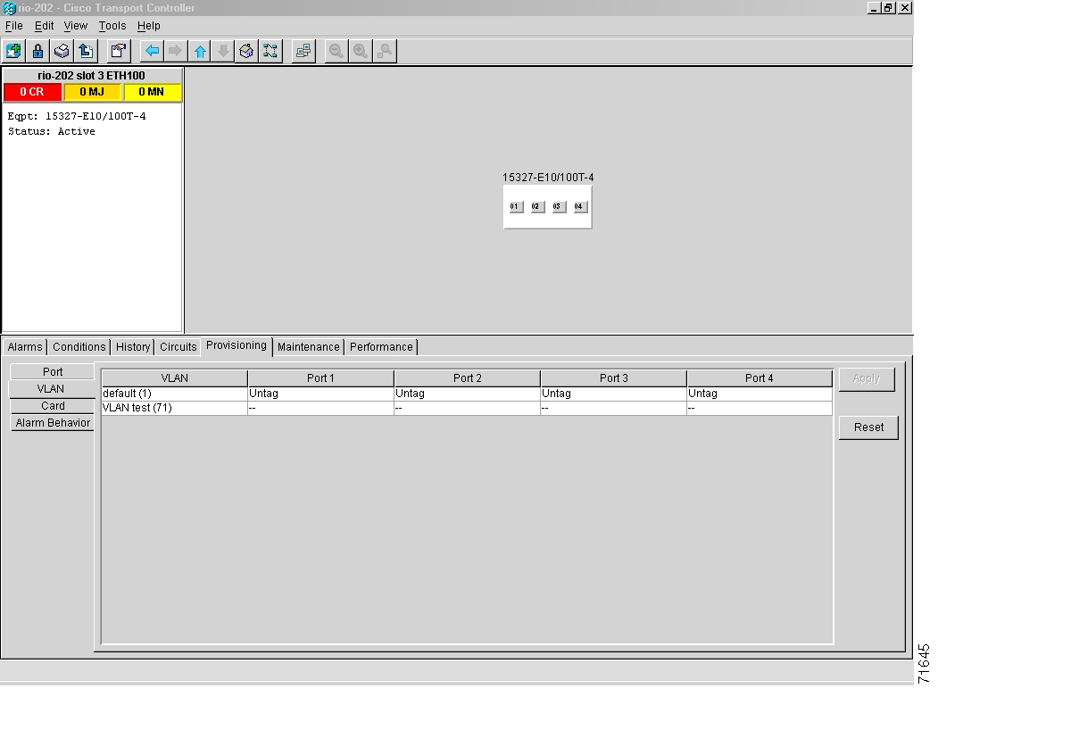
Procedure: Provision Ethernet Ports for VLAN Membership
Step 1
Step 2
Figure 9-22 Configuring VLAN membership for individual Ethernet ports
Step 3
If a port is a member of only one VLAN, go to the row of that VLAN and choose Untag from the Port column. Choose -- for all the other VLAN rows in that Port column. The VLAN with Untag selected can connect to the port, but other VLANs cannot access that port.
If a port is a trunk port, it connects multiple VLANs to an external device, such as a switch, that also supports trunking. A trunk port must have tagging (IEEE 802.1Q) enabled for all VLANs that connect to that external device. Choose Tagged for all VLAN rows that need to be trunked. Choose Untag for each of the VLAN rows in the trunk port column that do not need to be trunked, for example, the default VLAN. Each Ethernet port must attached to at least one untagged VLAN.
Step 4
Note
9.6 Spanning Tree (IEEE 802.1D)
The Cisco ONS 15327 operates Spanning Tree Protocol (STP) according to IEEE 802.1D when an Ethernet card is installed. STP operates over all packet-switched ports including Ethernet and SONET ports. On Ethernet ports, STP is disabled by default but may be enabled with a check box under the Provisioning > Port tabs at the card-level view. On SONET interface ports, STP activates by default and cannot be disabled.
The Ethernet card can enable STP on the Ethernet ports to allow redundant paths to the attached Ethernet equipment. STP spans cards so that both equipment and facilities are protected against failure.
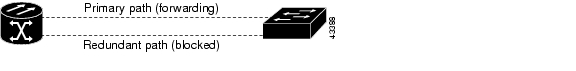
STP detects and eliminates network loops. When STP detects multiple paths between any two network hosts, STP blocks ports until only one path exists between any two network hosts ( Figure 9-23). The single path eliminates possible bridge loops. This is crucial for shared packet rings, which naturally include a loop.
Figure 9-23 STP-blocked path
To remove loops, STP defines a tree that spans all the switches in an extended network. STP forces certain redundant data paths into a standby (blocked) state. If one network segment in the STP becomes unreachable, the spanning-tree algorithm reconfigures the spanning-tree topology and reactivates the blocked path to reestablish the link. STP operation is transparent to end stations, which do not discriminate between connections to a single LAN segment or to a switched LAN with multiple segments. The ONS 15327 supports one STP instance per circuit and a maximum of eight STP instances per ONS 15327.
9.6.1 Multi-Instance Spanning Tree and VLANs
The ONS 15327 can operate multiple instances of STP to support VLANs in a looped topology. You can dedicate separate circuits across the SONET ring for different VLAN groups (i.e., one for private TLS services and one for Internet access). Each circuit runs its own STP to maintain VLAN connectivity in a multi-ring environment.
Procedure: Enable Spanning Tree on Ethernet Ports
Step 1
Step 2
Step 3
Step 4
9.6.2 Spanning-Tree Parameters
Default spanning tree parameters are appropriate for most situations. Contact the Cisco Technical Assistance Center (TAC) at 1-877-323-7368 before you change the default STP parameters.
At the node view, click the Maintenance > Etherbridge > Spanning Trees tabs to view spanning tree parameters.
9.6.3 Spanning-Tree Configuration
To view the spanning-tree configuration, at the node view click the Provisioning tab and Etherbridge subtab. Table 9-6 lists spanning-tree configuration information.
9.6.4 Spanning-Tree Map
The Circuit window shows forwarding spans and blocked spans on the spanning tree map.
Procedure: View the Spanning Tree Map
On the circuit window ( Figure 9-24), double-click an Ethernet circuit.
Figure 9-24 The Spanning-tree map on the Circuit window
Note
9.6.5 Ethernet Performance Screen
CTC provides Ethernet performance information that includes line-level parameters, the amount of port bandwidth used, and historical Ethernet statistics.
9.6.5.1 Statistics Window
The Ethernet statistics screen lists Ethernet parameters at the line level. Table 9-7 defines the parameters. Display the CTC card view for the Ethernet card and click the Performance > Statistics tabs to display the screen.
The Baseline button resets the values on the Statistics tab to zero. The Refresh button manually refreshes statistics. Auto-Refresh sets a time interval for automatic refresh of statistics to occur.
9.6.5.2 Line Utilization Window
The Line Utilization window shows the percentage of line, or port, bandwidth used and the percentage used in the past. Display the CTC card view and click the Performance and Utilization tabs to display the window. From the Interval menu, choose a time segment interval. Valid intervals are 1 minute, 15 minutes, 1 hour, and 1 day. Press Refresh to update the data.
9.6.5.3 Utilization Formula
The utilization screen numbers may differ from the numbers encountered on an Ethernet test set. The line utilization numbers express the average of ingress and egress traffic as a percentage of the total capacity. Line utilization is calculated with the following formula: (InOctets + OutOctets)*8 bits/octets/100/ intervals*(maxRate*2). Intervals are defined in seconds. maxRate is defined by raw bits/second in one direction for the circuit. maxRate is multiplied by 2 in the denominator to get the raw bit rate in both directions.
Table 9-8 maxRate for STS Circuits
STS-1
51840000 bps
STS-3c
155000000 bps
STS-6c
311000000 bps
STS-12c
622000000 bps
This formula does not take into account the HDLC headers, SONET header, and inter-frame gap. This means that the line utilization numbers do not reach 100 percent. It also means that smaller packet sizes result in lower utilization figures.
Note
9.6.5.4 History Window
The Ethernet History window lists past Ethernet statistics. At the CTC card view, click the Performance tab and History subtab to view the window. Choose the appropriate port from the Line menu and the appropriate interval from the Interval menu. Press Refresh to update the data.
9.6.6 Ethernet Maintenance Screen
Display an Ethernet card in CTC card view and choose the Maintenance tab to display MAC address and bandwidth information.
9.6.6.1 MAC Table
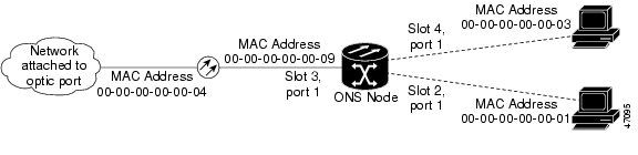
A MAC address is a hardware address that physically identifies a network device. The ONS 15327 MAC table, also known as the MAC forwarding table, allows you to see all of the MAC addresses attached to the enabled ports of an Ethernet card or an Ethernet Group. This includes the MAC address of the network device attached directly to the port and any MAC addresses on the network linked to the port. The MAC addresses table lists the MAC addresses stored by the ONS 15327 and the VLAN, Slot/Port/STS, and circuit that links the ONS 15327 to each MAC address ( Figure 9-25).
Figure 9-25 MAC addresses recorded in the MAC table
Procedure: Retrieve the MAC Table Information
Step 1
Step 2
Step 3
Note
9.6.6.2 Trunk Utilization Window
The Trunk Utilization window is similar to the Line Utilization window, but Trunk Utilization shows the percentage of circuit bandwidth used rather than the percentage of line bandwidth used. Click the Maintenance > Ether Bridge > Trunk Utilization tabs to view the window. Choose a time segment interval from the Interval menu.
Note
9.7 Remote Monitoring Specification Alarm Thresholds
The ONS 15327 features Remote Monitoring (RMON) that allows network operators to monitor the health of the network with a network management system (NMS). For a detailed description of the ONS SNMP implementation, see Chapter 11, "SNMP."
One of the ONS 15327 RMON MIBs is the Alarm group. The alarm group consists of the alarmTable. An NMS uses the alarmTable to find the alarm-causing thresholds for network performance. The thresholds apply to the current 15-minute interval and the current 24-hour interval. RMON monitors several variables, such as Ethernet collisions, and triggers an event when the variable crosses a threshold during that time interval. For example, if a threshold is set at 1000 collisions and 1001 collisions occur during the 15-minute interval, an event triggers. CTC allows you to provision these thresholds for Ethernet statistics.
Note
Note
Procedure: Creating Ethernet RMON Alarm Thresholds
Step 1
Step 2
Step 3
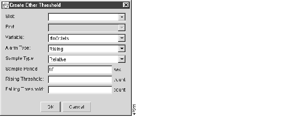
The Create Ether Threshold dialog box appears.
Figure 9-26 Creating RMON thresholds
Step 4
Step 5
Step 6
Step 7
Step 8
Step 9
Step 10
Note
Step 11
A falling threshold is the counterpart to a rising threshold. When the number of occurrences is above the rising threshold and then drops below a falling threshold, it resets the rising threshold. For example, when the network problem that caused 1001 collisions in 15 minutes subsides and creates only 799 collisions in 15 minutes, occurrences fall below a falling threshold of 800 collisions. This resets the rising threshold so that if network collisions again spike over a 1000 per 15 minute period, an event again triggers when the rising threshold is crossed. An event is triggered only the first time a rising threshold is exceeded. (Otherwise a single network problem might cause a rising threshold to be exceeded multiple times and cause a large number of events.)
Step 12
![]()
![]()
![]()
![]()
![]()
![]()
![]()
![]()
Posted: Mon Feb 25 05:52:09 PST 2008
All contents are Copyright © 1992--2008 Cisco Systems, Inc. All rights reserved.
Important Notices and Privacy Statement.