|
|

Table Of Contents
7.1 Performance Monitoring Thresholds
7.2 Provisioning Electrical Cards
7.2.1 Mapping Card Provisioning and Performance Monitoring
7.3 Provisioning Optical Cards
7.3.1 Modifying Transmission Quality
7.5.2 External Output Controls
7.5.3 Provisioning Orderwire Pass-Through
Card Provisioning
This chapter provides Cisco ONS 15327 procedures for:
•
Changing the default transmission parameters for electrical (DS-N) and optical (OC-N) cards
•
•
Note
Because much of the electrical and optical card provisioning involves PM thresholds, see Chapter 8, "Performance Monitoring," for definitions and general information about ONS 15327 performance monitoring parameters. In addition, refer to the Telcordia GR-1230-CORE, GR-820-CORE, and GR-253-CORE documents. The default thresholds delivered with ONS 15327 cards are based on specifications contained in those documents.
Note
7.1 Performance Monitoring Thresholds
ONS 15327 card default thresholds are based on GR-253-CORE and GR-820-CORE. If you change their settings, the following rules apply:
•
•
•
7.2 Provisioning Electrical Cards
The ONS 15327 electrical cards (DS-1 ports on the XTC-14 and XTC-28-3 and DS-3 ports on the XTC-28-3) are pre-provisioned with settings that you can modify to manage transmission quality. When you open an XTC card in CTC and select the Provisioning tab, the following subtabs are commonly displayed:
•
•
•
•
•
•
Table 7-1 provides an overview of DS-1 and DS-3 parameters (an X means the item is available for the card).
7.2.1 Mapping Card Provisioning and Performance Monitoring
The card provisioning items in Table 7-1 map to the performance monitoring (PM) parameters displayed when you click the Performance tab. Table 7-2 shows the relationship between the card provisioning items and the PM parameters.
7.2.2 DS-1 Card Parameters
The ONS 15327XTC cards provide 14 (XTC-14 or 28 (XTC-28-3) DS-1 ports. Each port operates at 1.544 Mbps. Default thresholds are based on recommendations in GR-820-CORE, Section 4.0.
Procedure: Modify Line and Threshold Settings for the DS-1 Card
Step 1
Step 2
Figure 7-1 Provisioning line parameters on the DS1-14 card
Step 3
Note
Step 4
Step 5
Step 6
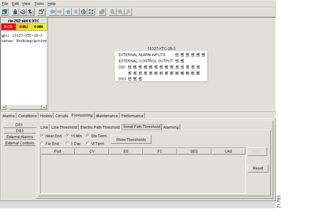
7.2.3 DS-3 Card Parameters
The ONS 15327 XTC-28-3 card provides 3 DS-3 ports. Each port operates at 44.736 Mbps. Default thresholds are based on recommendations in GR-820-CORE, Section 5.0.
Procedure: Modify Line and Threshold Settings for the DS-3 Card
Step 1
Step 2
Step 3
Note
Step 4
Step 5
Step 6
7.3 Provisioning Optical Cards
This section explains how to modify transmission quality by provisioning line and threshold settings for OC-N cards.
7.3.1 Modifying Transmission Quality
The OC-3, OC-12 and OC-48 cards are pre-provisioned with settings that you can modify to manage transmission quality. Depending on the optical card, you can specify thresholds for near and far end nodes at the Line, Section, and Path levels for 15-minute and one day intervals.
Procedure: Provision Line Transmission Settings for OC-N Cards
Step 1
Step 2
Step 3
Table 7-5 OC-N Card Line Settings on the Provisioning > Line Tab
Port #
Port number
•
•
Port Name
Name of the OC-N port
32 alpha-numeric characters
SF BER Level
Sets the signal fail bit error rate
•
•
•
SD BER Level
Sets the signal degrade bit error rate
•
•
•
•
•
Provides Synch
If checked, the card is provisioned as a network element timing reference on the Provisioning > Timing tabs
Read-only
•
•
Enable Synch Messages
Enables synchronization status messages (S1 byte), which allow the node to choose the best timing source
•
•
Send Do Not Use
When checked, sends a DUS (do not use) message on the S1 byte
•
•
PJ Sts Mon #
Sets the STS that will be used for pointer justification. If set to 0, no STS is monitored. Only one STS can be monitored on each OC-N port. See the "Pointer Justification Count Reference" section on page 8-13 for more information.
•
•
•
Status
Places port in or out of service
•
•
Type
Defines the port as SONET or SDH.
Sonet only
Step 4
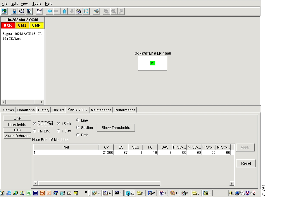
Procedure: Provision Threshold Settings for OC-N Cards
Step 1
Step 2
Figure 7-2 Provisioning thresholds for the OC48 IR 1310 card
Step 3
Default thresholds apply to all optical cards unless otherwise specified.
Table 7-6 OC-N Card Threshold Settings on the Provisioning > Thresholds Tab
Port number
•
•
Coding violations
Numeric. Defaults (15 min/1 day):
Line
•
•
•
Section
•
Path
•
Errored seconds
Numeric. Default (15 min/1 day):
Line
•
Section
•
Path
•
Severely errored seconds
Numeric. Defaults (15 min/1 day):
Line
•
Section
•
Path
•
Failure count
Numeric. Defaults (15 min/1 day):
Line
•
Path
•
Unavailable seconds
Numeric. Defaults (15 min/1 day):
Line
•
Path
•
Severely errored framing seconds
Numeric. Defaults (15 min/1 day):
Section
•
Positive Pointer Justification Count, STS Path detected. See the "Performance Monitoring for Optical Cards" section on page 8-24 for more information.
Numeric. Defaults (15 min/1 day):
Line
•
Negative Pointer Justification Count, STS Path detected. See the "Performance Monitoring for Optical Cards" section on page 8-24 for more information.
Numeric. Defaults (15 min/1 day):
Line
•
•
Positive Pointer Justification Count, STS Path generated. See the "Performance Monitoring for Optical Cards" section on page 8-24 for more information.
Numeric. Defaults (15 min/1 day):
Line
•
•
Negative Pointer Justification Count, STS Path generated. See the "Performance Monitoring for Optical Cards" section on page 8-24 for more information.
Numeric. Defaults (15 min/1 day):
Line
•
•
Protection Switching Count (Line)
Numeric. Defaults (15 min/1 day):
Line
•
Protection Switch Duration (Line)
Numeric. Defaults (15 min/1 day):
Line
•
Protection Switching Count - Working line
BLSR is not supported on the OC-3 card; therefore, the PSC-W, PSC-S, and PSC-R PMs do not increment.
Numeric. Defaults (15 min/1 day):
Line
•
Protection Switching Duration - Working line
BLSR is not supported on the OC-3 card; therefore, the PSD-W, PSD-S, and PSD-R PMs do not increment.
Numeric. Defaults (15 min/1 day):
Line
•
Protection Switching Duration - Span
BLSR is not supported on the OC-3 card; therefore, the PSC-W, PSC-S, and PSC-R PMs do not increment.
Numeric. Defaults (15 min/1 day):
Line
•
Protection Switching Duration - Span
BLSR is not supported on the OC-3 card; therefore, the PSD-W, PSD-S, and PSD-R PMs do not increment.
Numeric. Defaults (15 min/1 day):
Line
•
Protection Switching Duration - Ring
BLSR is not supported on the OC-3 card; therefore, the PSC-W, PSC-S, and PSC-R PMs do not increment.
Numeric. Defaults (15 min/1 day):
Line
•
Protection Switching Duration - Ring
BLSR is not supported on the OC-3 card; therefore, the PSD-W, PSD-S, and PSD-R PMs do not increment.
Numeric. Defaults (15 min/1 day):
Line
•
Click Apply.
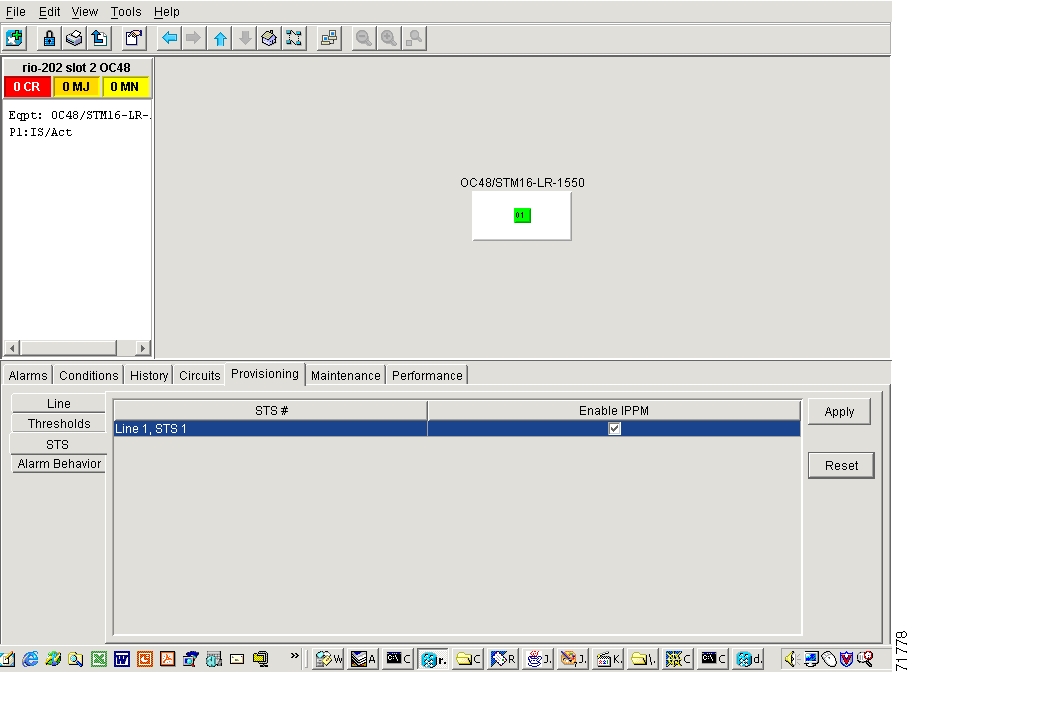
7.4 Provisioning IPPM
Intermediate-Path Performance Monitoring (IPPM) allows you to transparently monitor traffic originating on DS-1 or DS-3 ports on XTC cards (Path Terminating Equipment) as it passes through OC-3, OC-12, and OC-48 cards (Line Terminating Equipment). To use IPPM, you create the STS circuit on the DS-N cards, then enable IPPM on the OC-N cards that carry the circuit.
For example, suppose you have an STS circuit that originates and terminates on DS-N ports at Nodes 1 and 4. You want to monitor the circuit as it passes through OC-N cards at Nodes 2 and 3. To do this, you enable IPPM on the OC-N card by selecting the appropriate STS, in this example, STS 1 ( Figure 7-3).
Figure 7-3 IPPM provisioned for STS 1 on an OC-12 card
After enabling IPPM, performance is displayed on the Performance tab for the OC-48 card. IPPM enables per-path statistics for STS CV-P (coding violations), STS ES-P (errored seconds), STS FC-P (failure count), STS SES-P (severely errored seconds), and STS UAS-P (unavailable seconds). Additional rows will appear in the table on the STS IPPM subtab as circuits are created. After the circuits are created, you can enable each for IPPM collection. See Chapter 8, "Performance Monitoring" for a definition of every parameter.
Procedure: Enable Intermediate-Path Performance Monitoring
Step 1
Step 2
Step 3
Step 4
Step 5
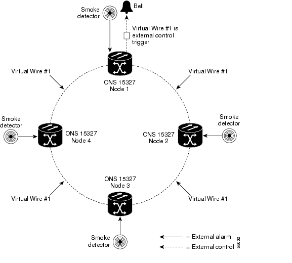
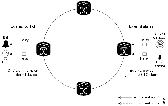
7.5 Using Virtual Wires
Provisioning the external alarms provides a "virtual wires" option that you can use to route external alarms and controls from different nodes to one or more alarm collection centers. For example, in Figure 7-4, smoke detectors provisioned as external alarms at Nodes 1, 2, 3, and 4 are assigned to Virtual Wire #1, and Virtual Wire #1 is provisioned as the trigger (external output control) for an external bell at Node 1.
Figure 7-4 Example of external alarms and controls in a virtual wire configuration
7.5.1 External Input Alarms
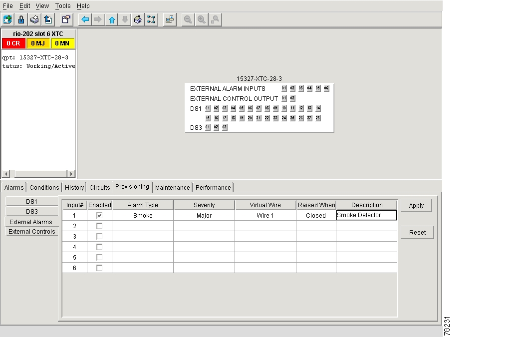
Use external alarms for sensors such as open doors, temperature sensors, flood sensors, and other environmental conditions.
Provision External Alarms
Step 1
Step 2
Step 3
Step 4
•
•
•
•
•
•
Step 5
Step 6
Step 7
Figure 7-5 The External Alarms subtab showing the XTC-28-3 card
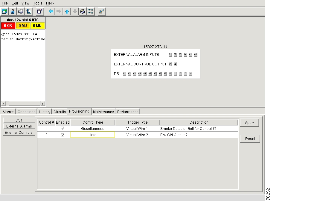
7.5.2 External Output Controls
Use external controls, or office alarms, to drive visual or audible devices such as bells and lights. The alarm-triggering conditions for the external controls can be the user-defined external input alarms (virtual wire), local severity-based alarms (e.g. trigger when any Major alarm happens), or remote severity-based alarms.
Provision External Controls
Step 1
Step 2
Step 3
Figure 7-6 The External Controls subtab showing the XTC-14 card
Step 4
•
•
•
•
Step 5
Step 6
Figure 7-7 shows a functional diagram of alarm input and output.
Figure 7-7 Example of the external alarm input and output process
7.5.3 Provisioning Orderwire Pass-Through
Orderwire allows onsite personnel to communicate with one another using standard phone sets. Although the ONS 15327 does not terminate orderwire (there is no RJ-11 jack), it can pass through Local and Express orderwire traffic using the SONET Orderwire overhead:
•
•
Use the E1 byte (Local) when making orderwire connections to section terminating equipment and the E2 byte (Express) when making orderwire connections to line terminating equipment. The ONS 15327 and ONS 15454 are both section and line terminating equipment. When provisioning orderwire pass-through across networks that are exclusively ONS 15327s and/or ONS 15454s, you can use either Local or Express orderwire. If other equipment will be used to pass or terminate orderwire traffic, consult the documentation for that equipment to determine if it is section or line terminating equipment.
Procedure: Provision Orderwire Pass-Through
Step 1
Step 2
Step 3
Step 4
Step 5
![]()
![]()
![]()
![]()
![]()
![]()
![]()
![]()
Posted: Mon Feb 25 05:47:33 PST 2008
All contents are Copyright © 1992--2008 Cisco Systems, Inc. All rights reserved.
Important Notices and Privacy Statement.